Fit Air Cleaner

I test fit the air cleaner to make sure there weren’t any issues with it. This really dresses up the engine and the black and bare aluminum theme for the engine really looks sweet.

The air cleaner comes with a spacer that raises the base 1″. I assume it is optional, but the base hits the raised boss on the left side of the picture without it. Hopefully this doesn’t raise the air cleaner so high that it interferes with the body when installed in the car, but I can always cut it down a bit if necessary. This is a cheap piece of plastic, so I’ll probably upgrade to an aluminum one anyway.

I’m glad I did the test fit for another reason. I knew this air cleaner was held on by a center bolt that threads into the center of the throttle body and I assumed this was a standard size, but apparently that’s not true. The air cleaner came with a 1/4″-20 threaded rod that is 4″ long, but the FiTech unit is threaded for a 5/16″-18 rod. Summit Racing sells 1/4″-20 to 5/16″-18 adapters for $10-15, but you can buy an entire hold down kit that includes the adapter for $3…go figure.

Brake Fitting and Strut Reservoir Brackets

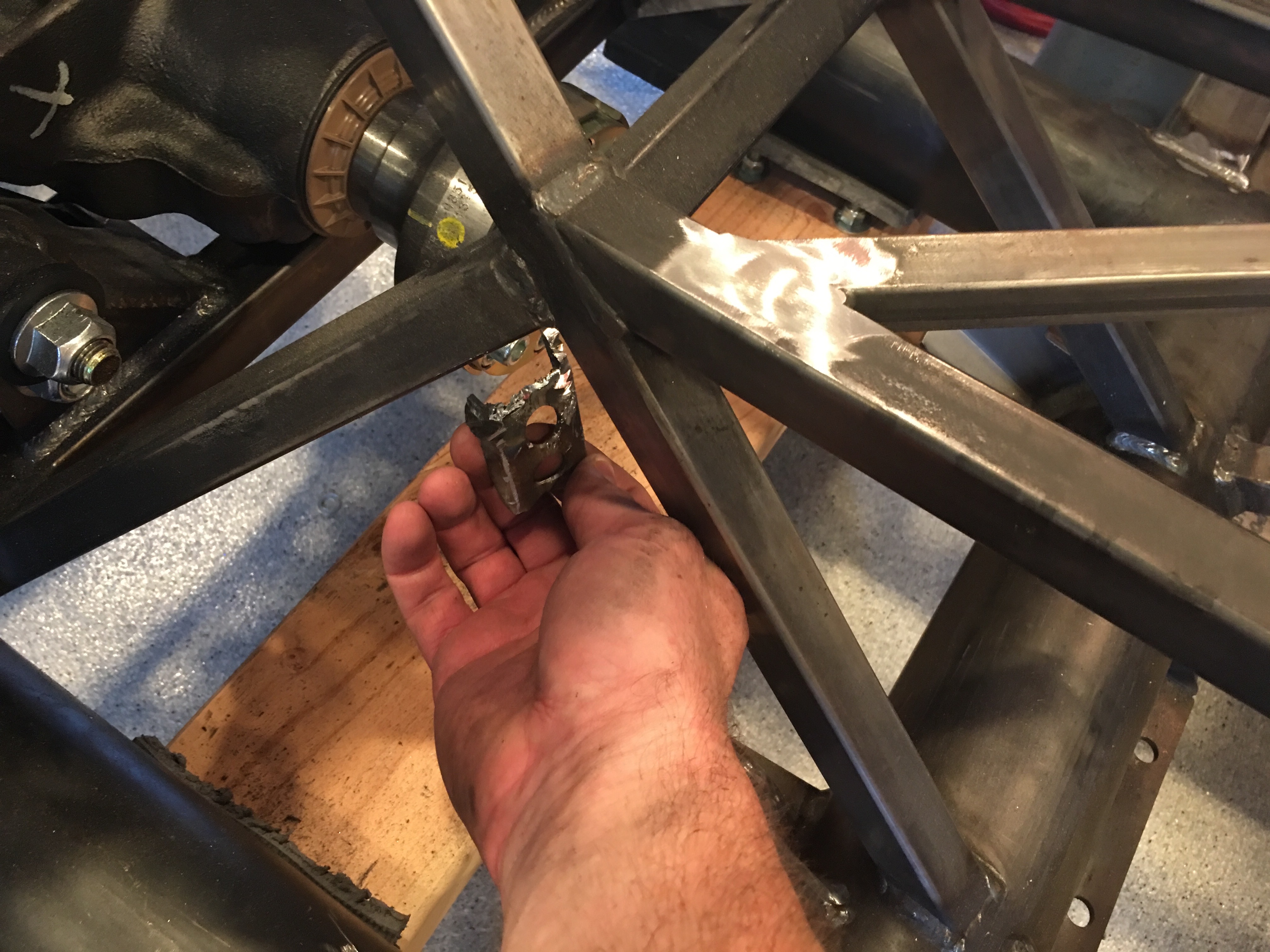
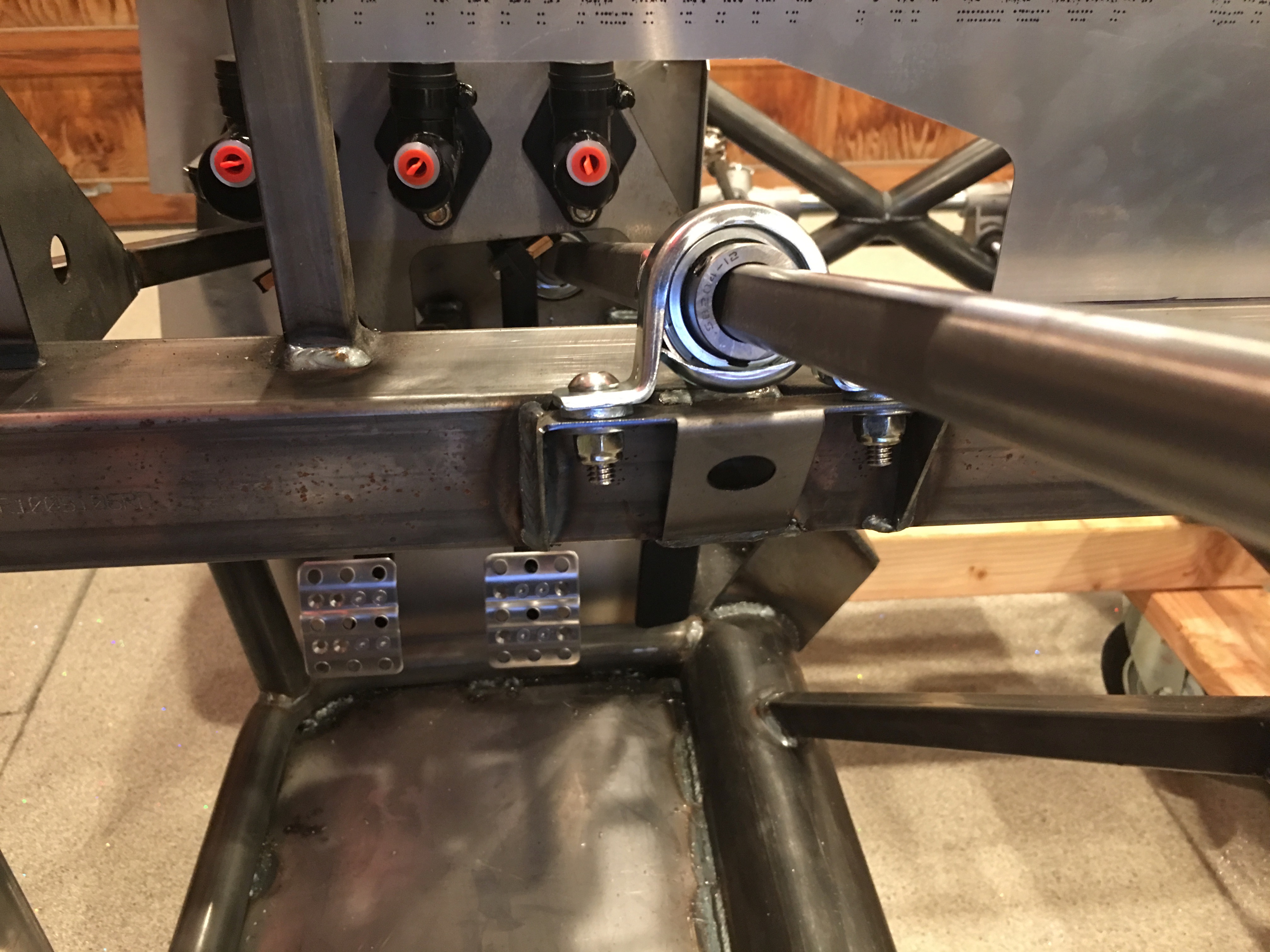
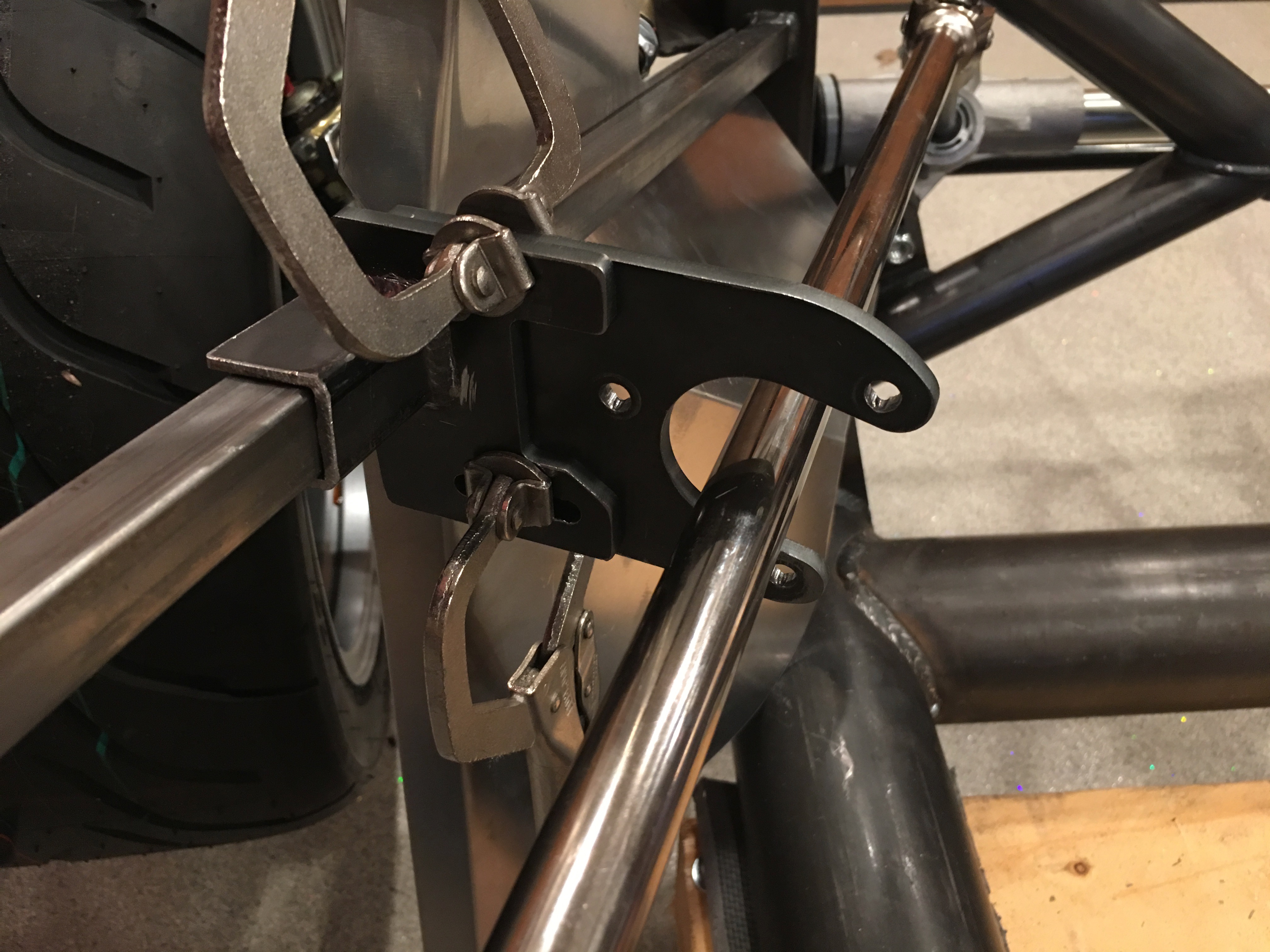
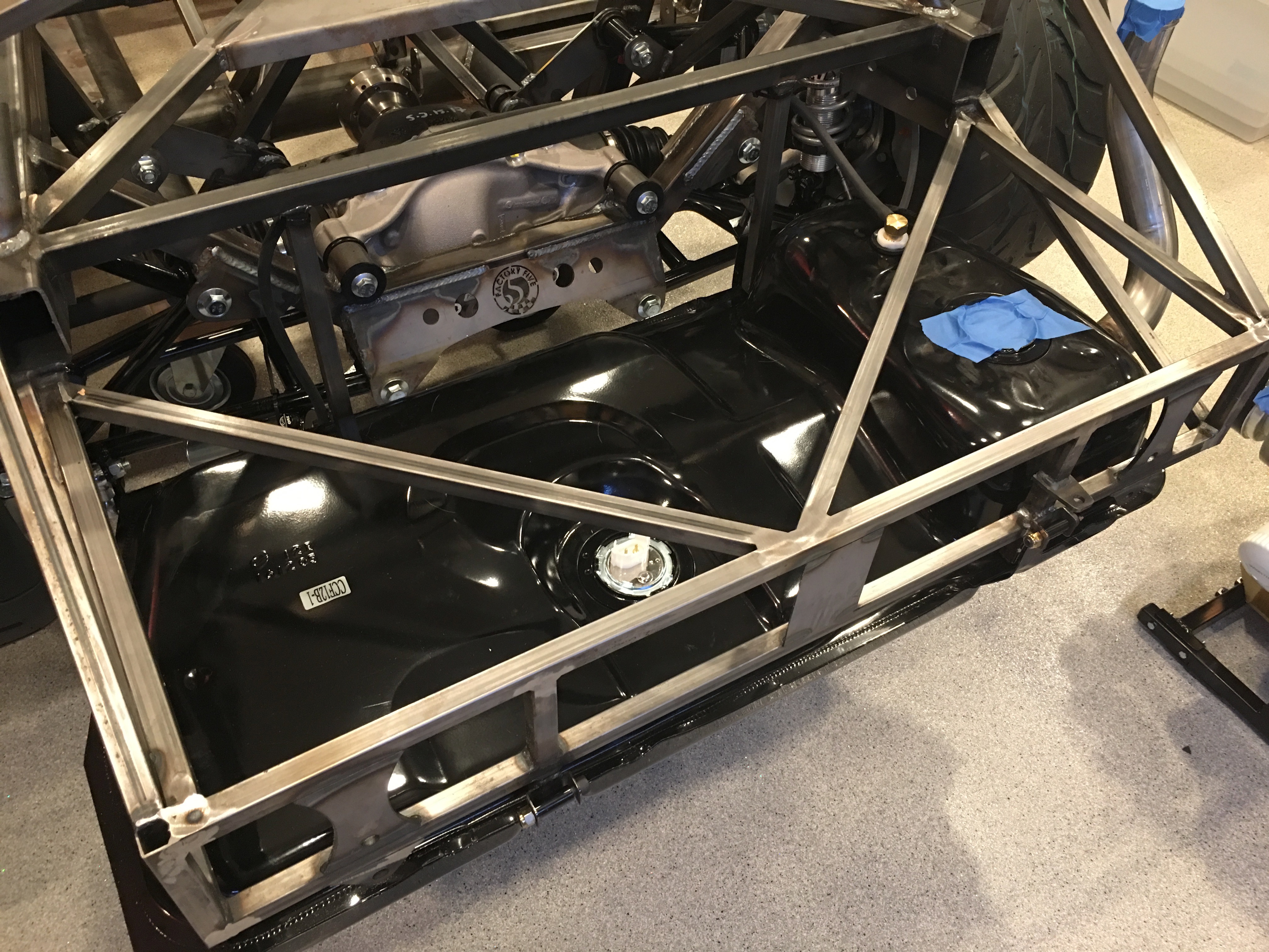
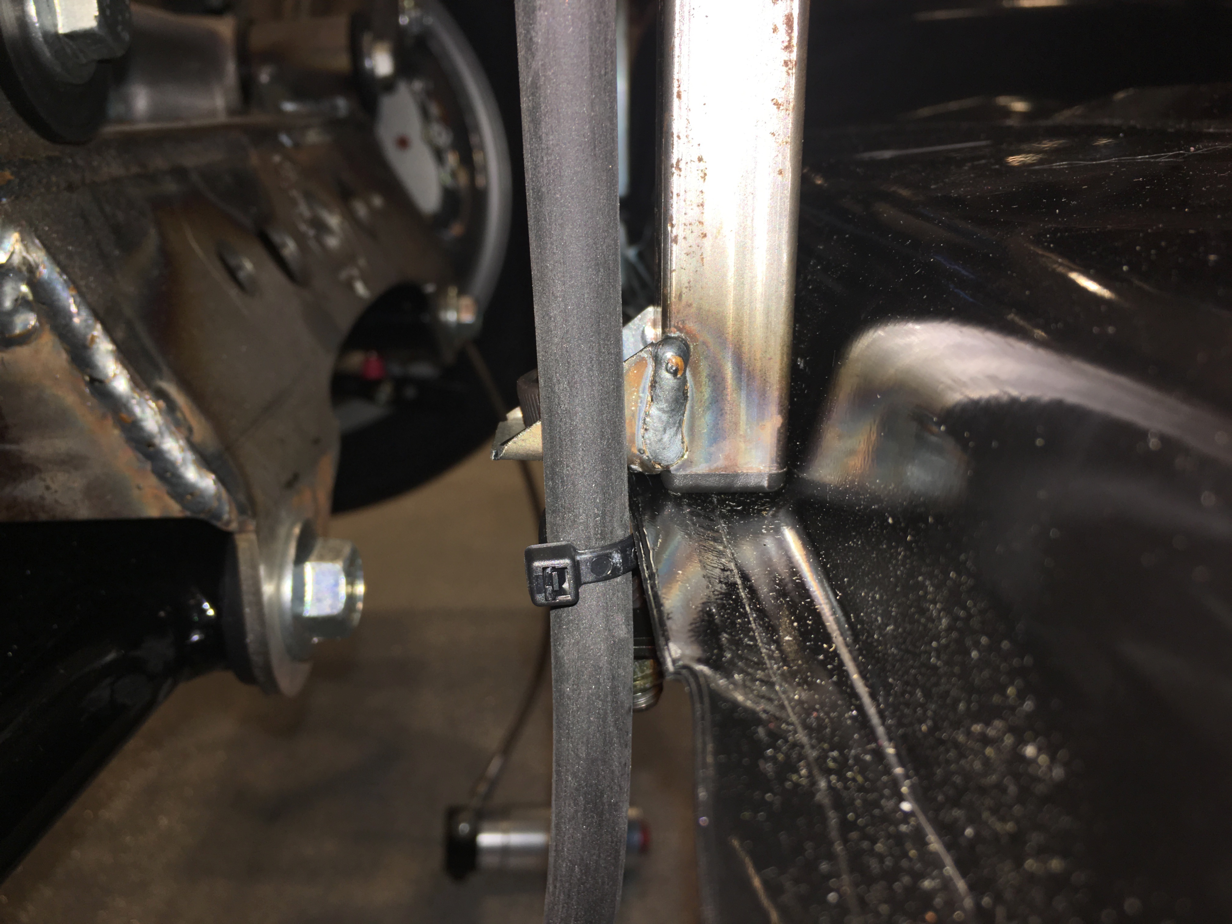
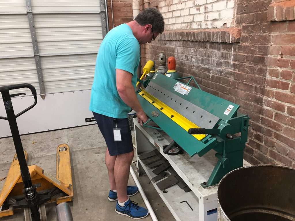
The Factory Five kit has rigid brake lines between the master cylinders and each of the wheel wells. At the wheel well, there is a fitting that transitions between the rigid line and a flexible stainless line that runs out to the caliper. This fitting is held in place with a small bracket. The kit only came with two of the brackets (probably because I deleted the brakes from the kit) and they’re stainless. Since I plan on welding the brackets on, I decided to fabricate four new brackets out of mild steel.

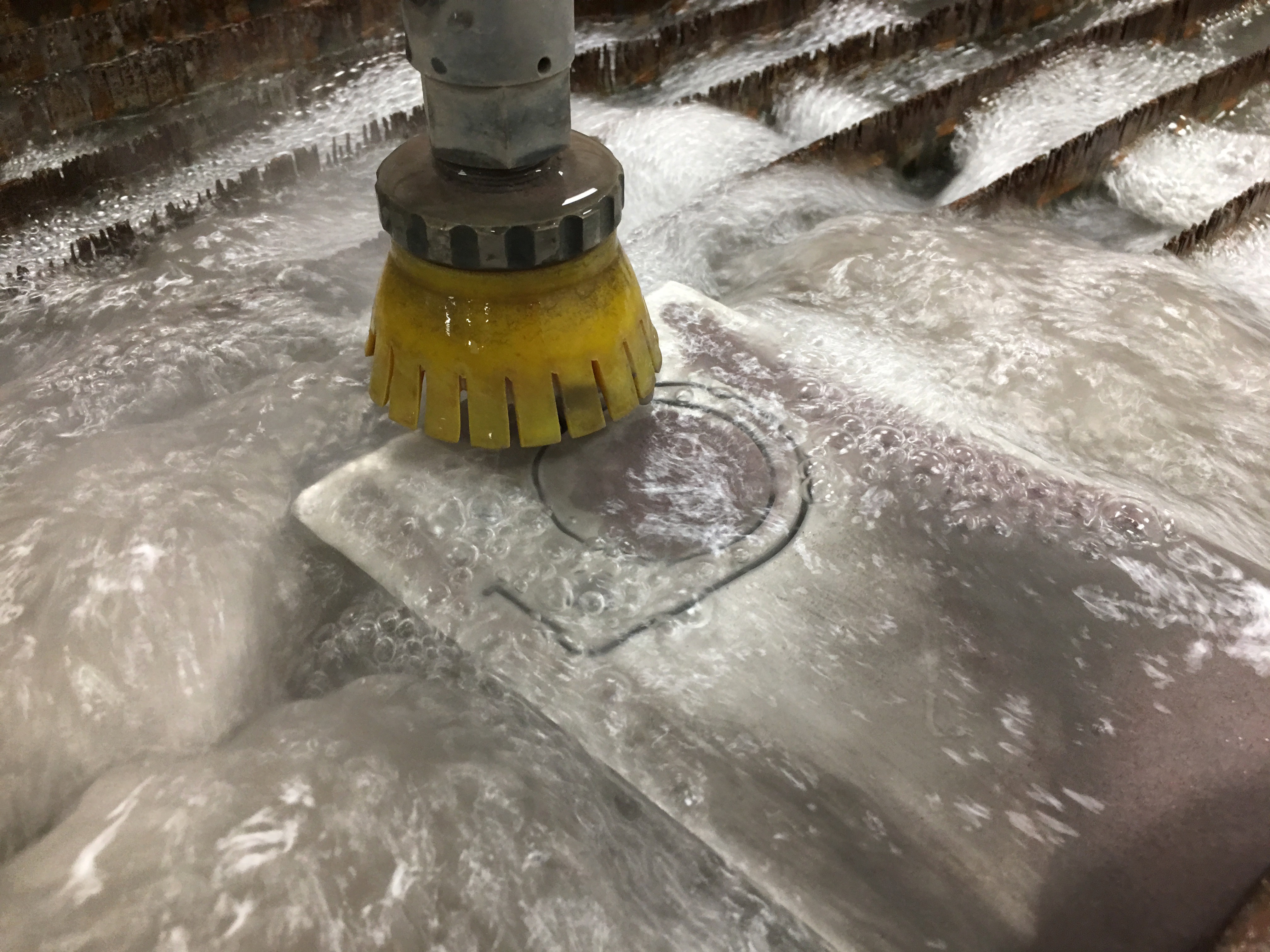
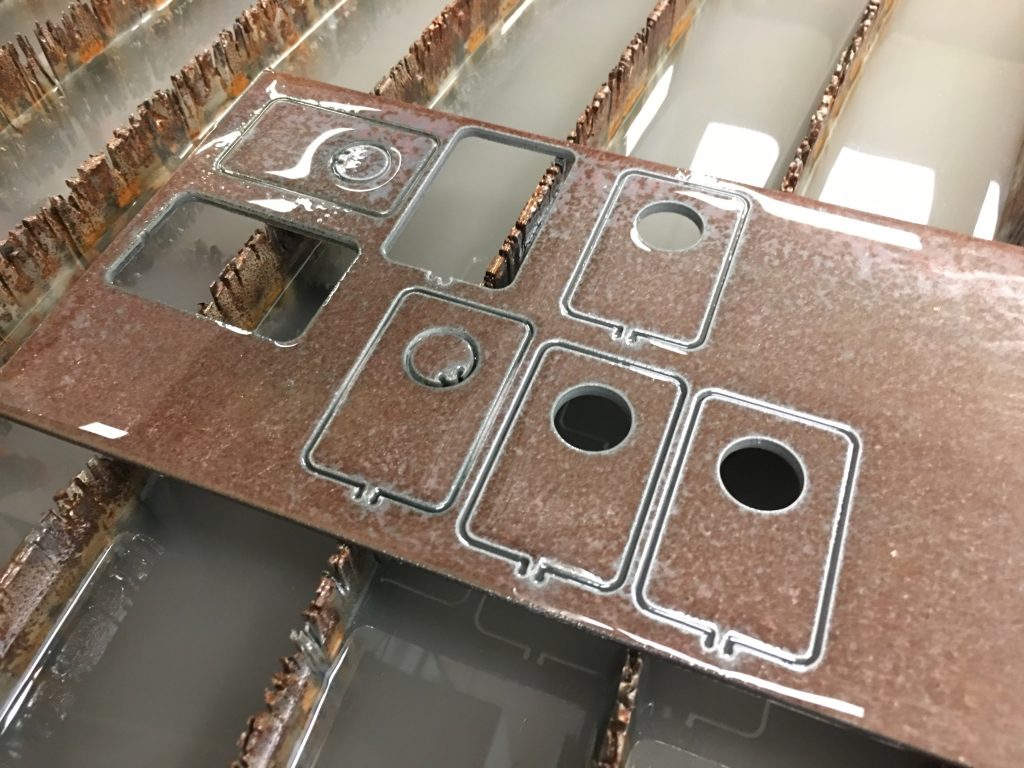
I drew up a simple bracket in Autodesk Mechanical and cut them out on the waterjet. It took a couple of tries with different tab size settings and cut speeds until we got four that we were happy with.

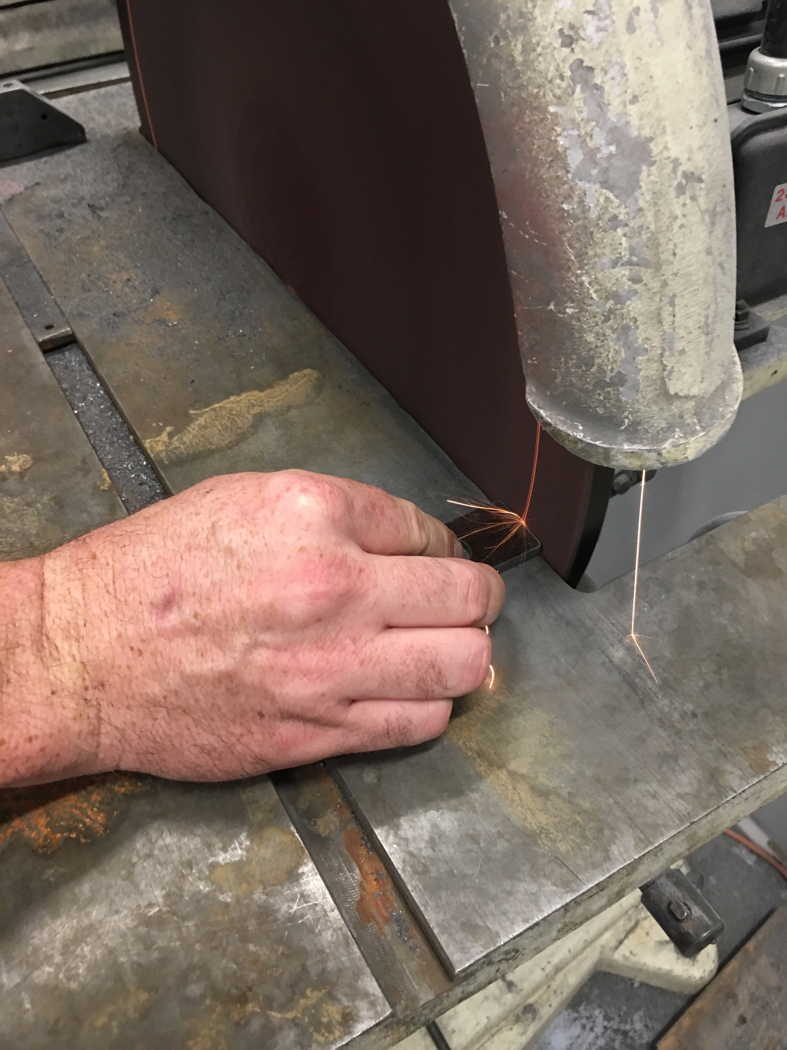
I used the disk grinder to sand off the tab and clean up the edges.

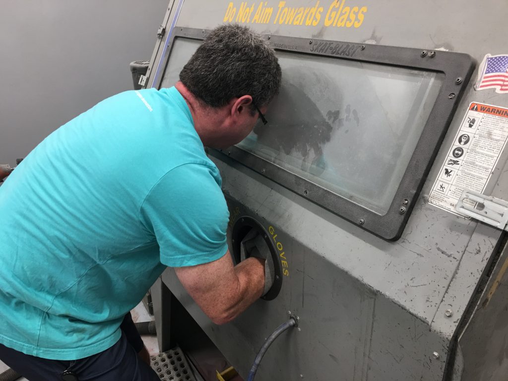
I then sandblasted all the rust off.

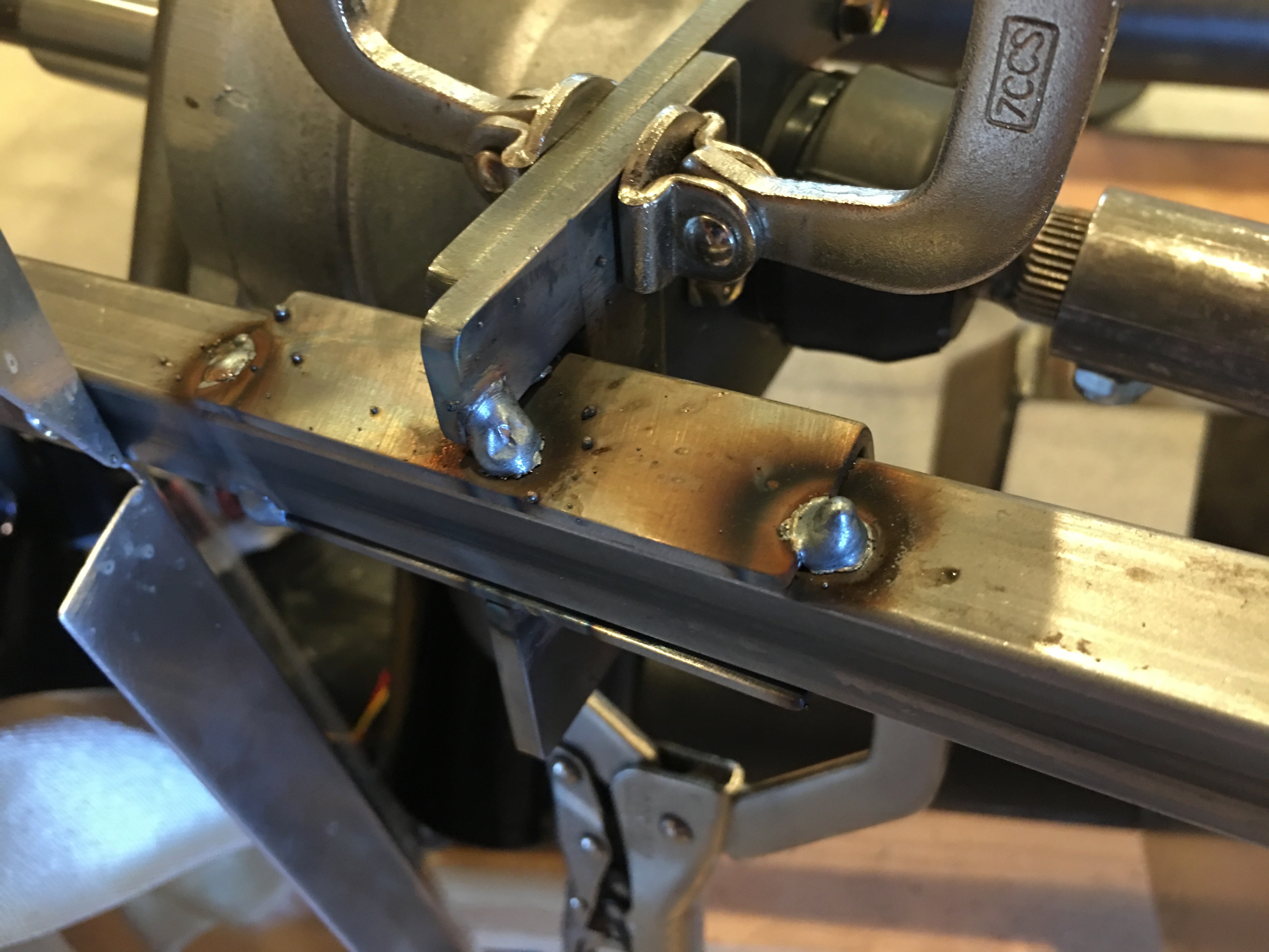
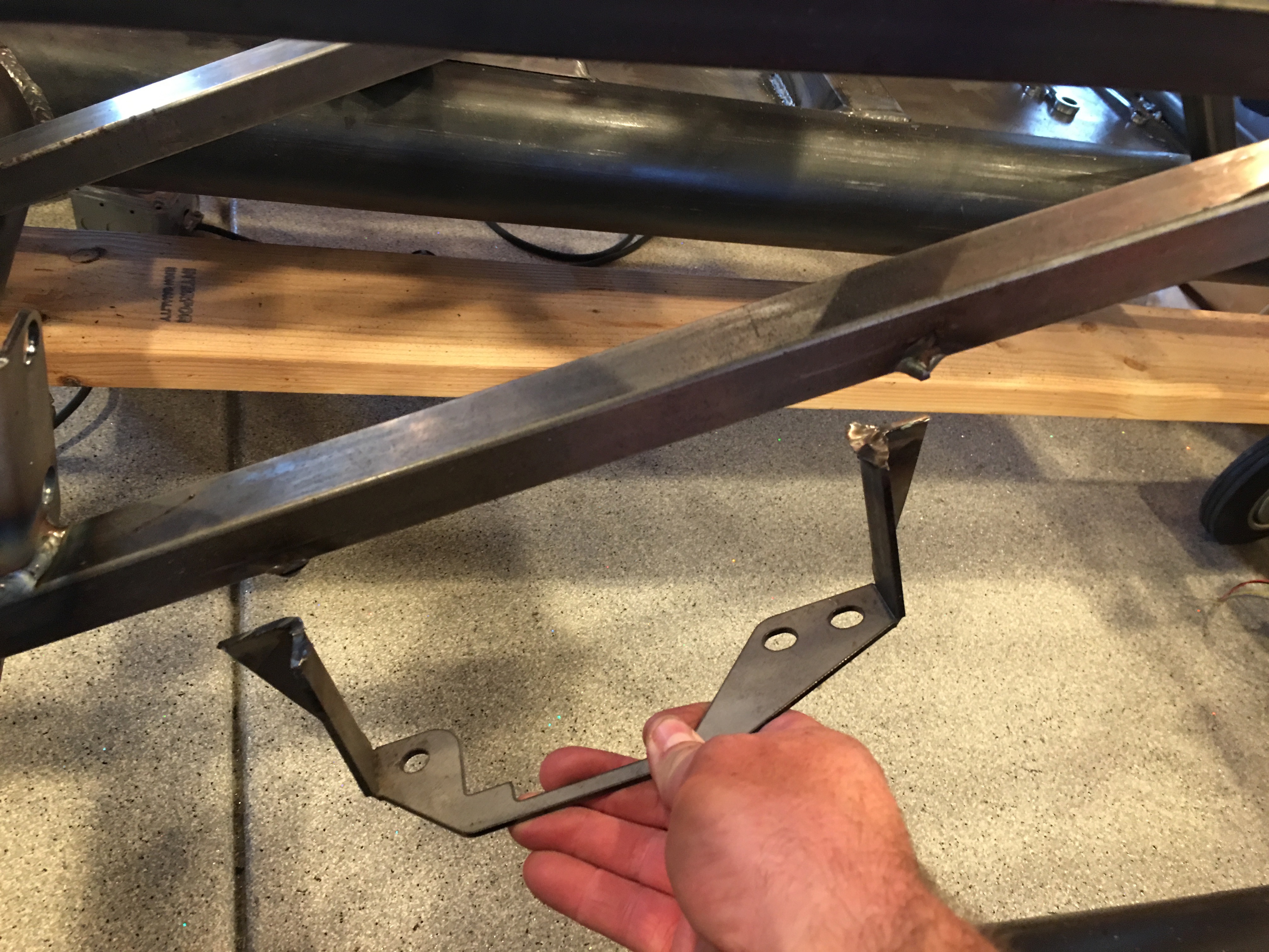
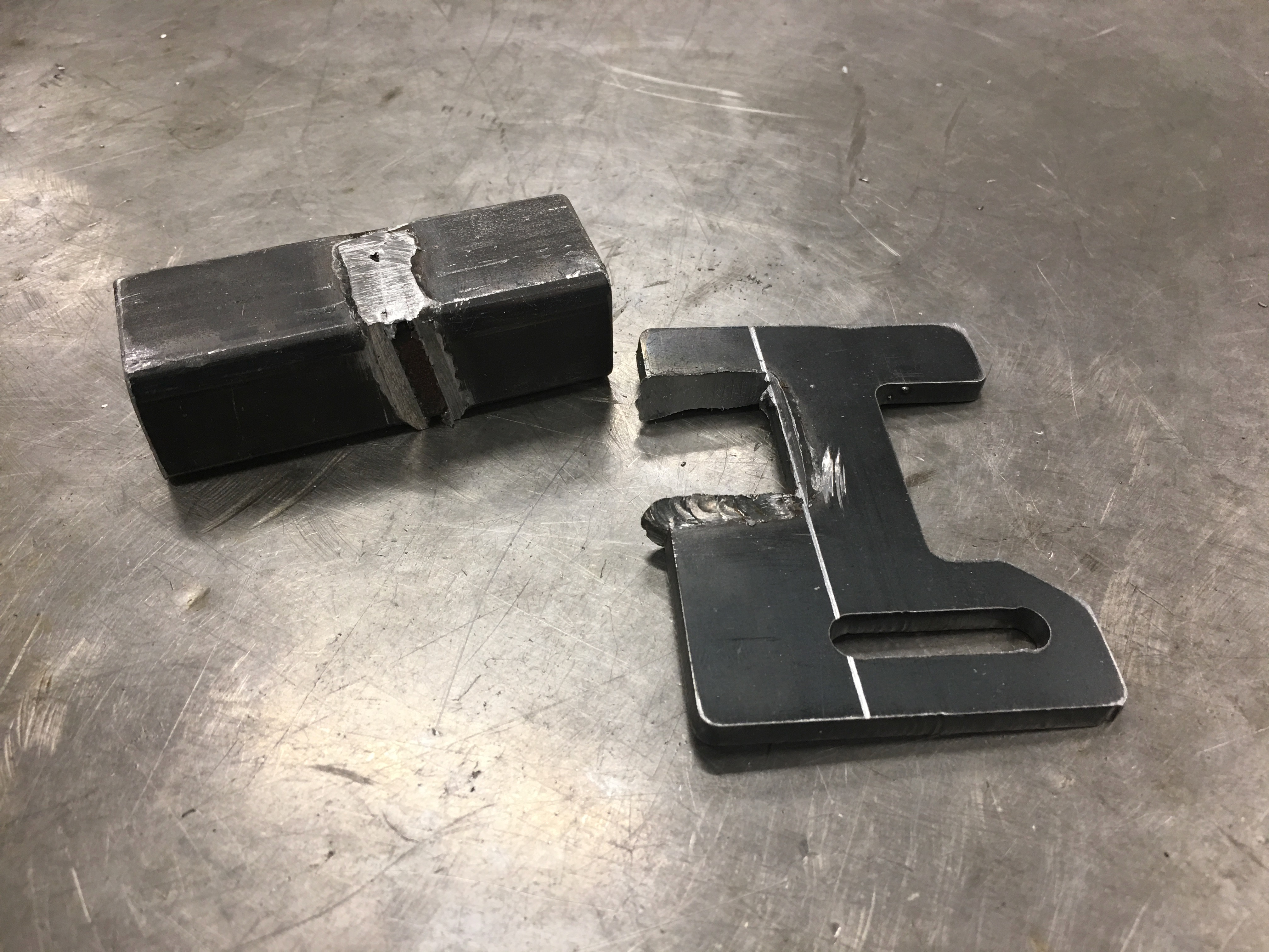
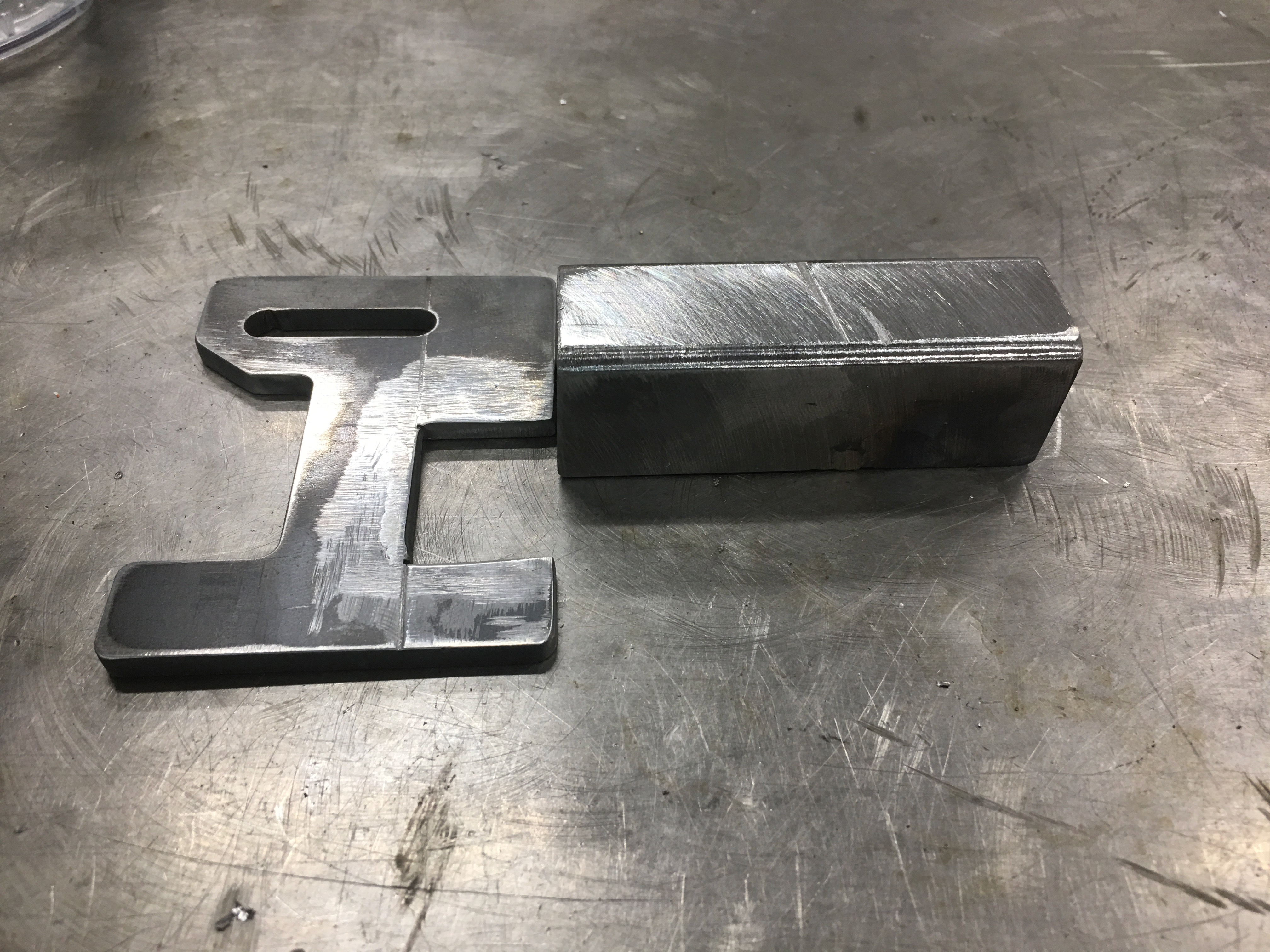
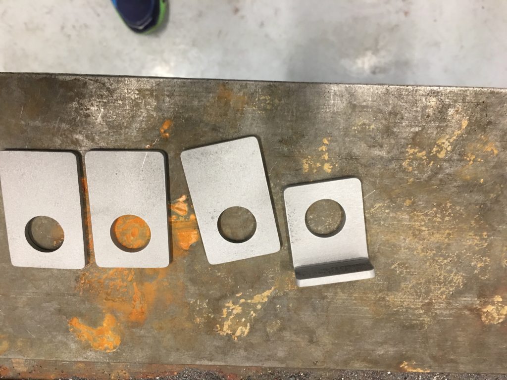
The parts from FFR have a couple of holes and are riveted to the side of the 3/4″ chassis tubing. Instead of riveting ours on, I put a bend in the brackets so that I can weld them to the top of the 3/4″ tubing.

Here’s one of the bent pieces along with the other three that are ready for bending.

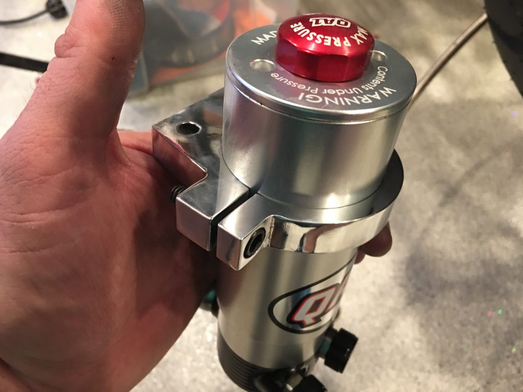
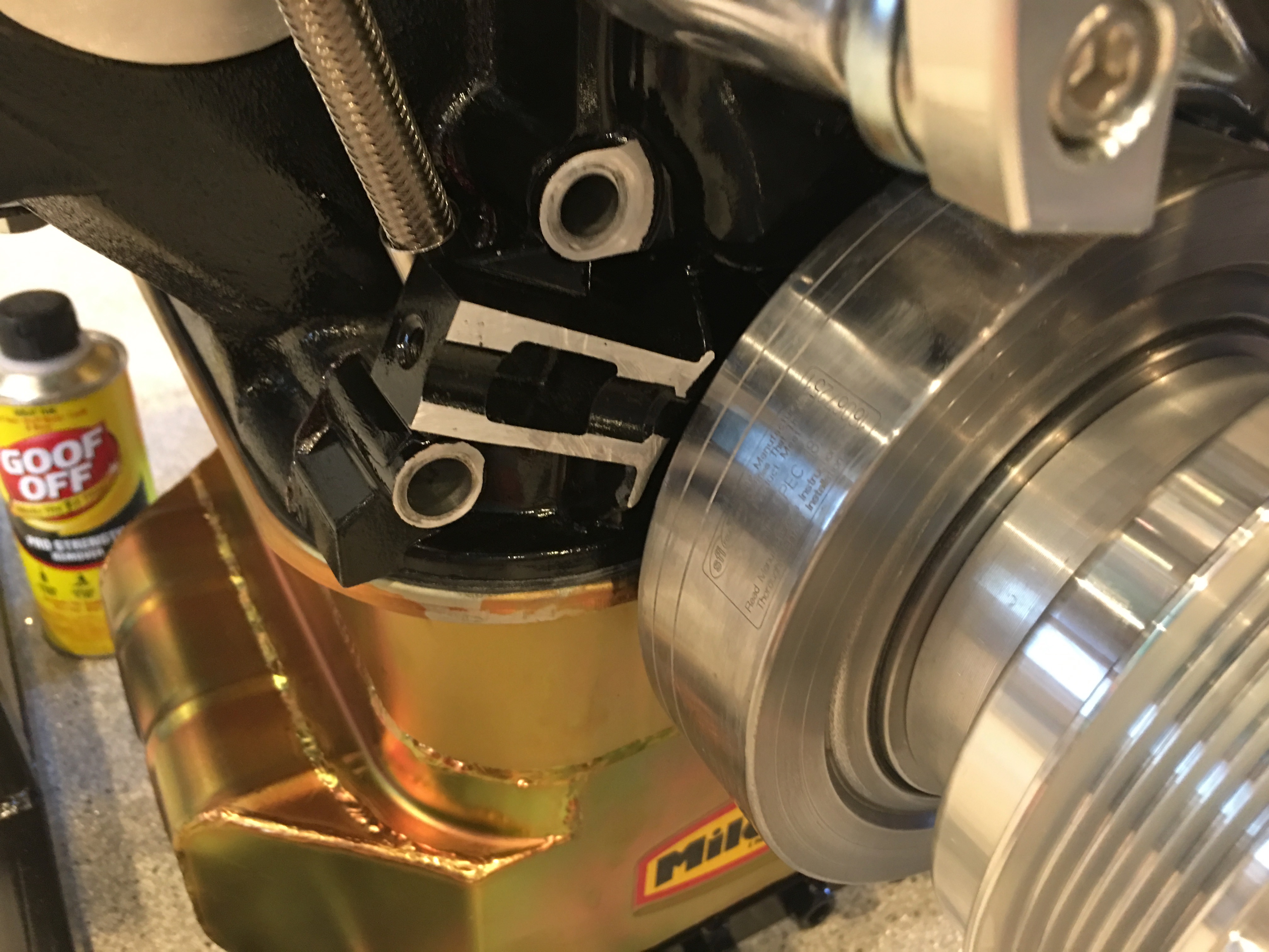
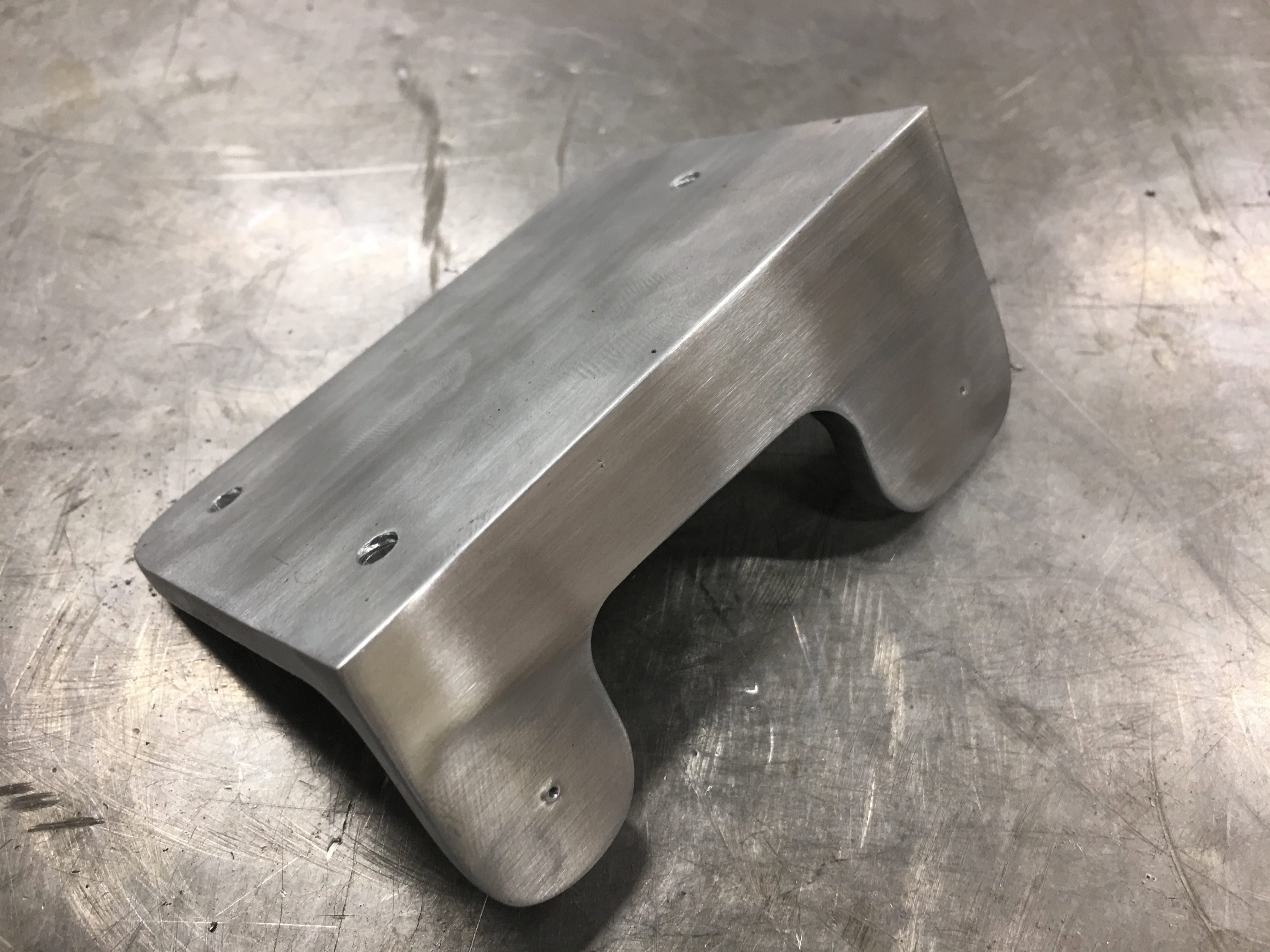
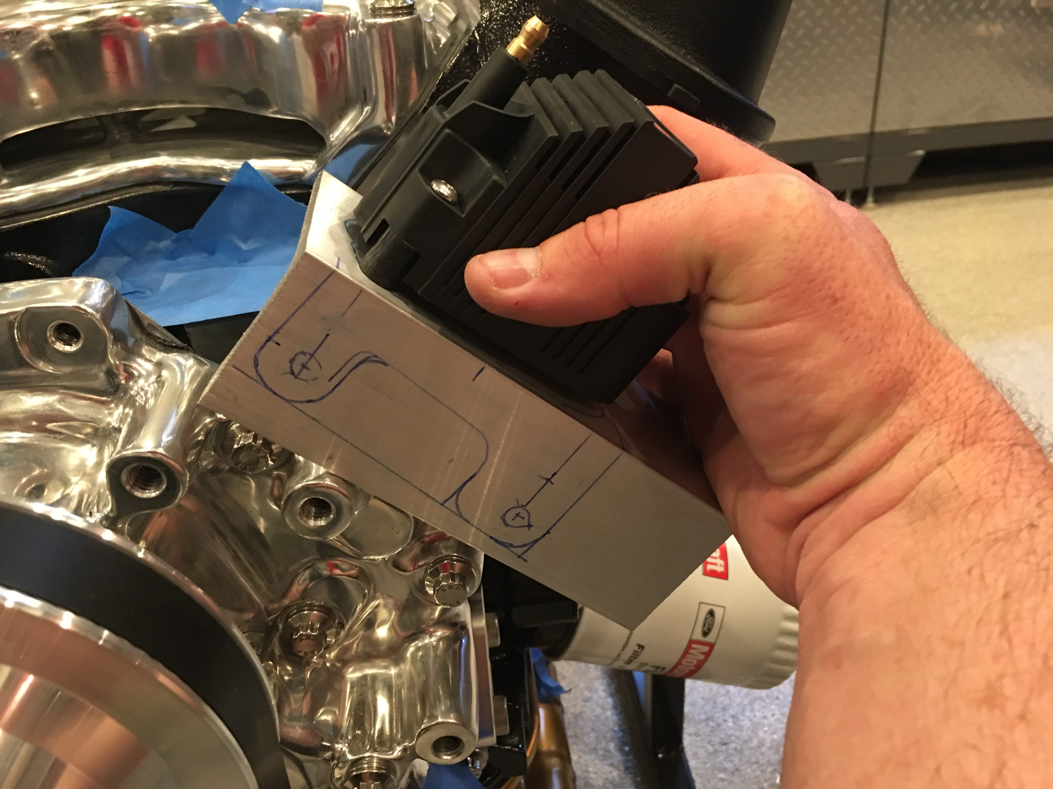
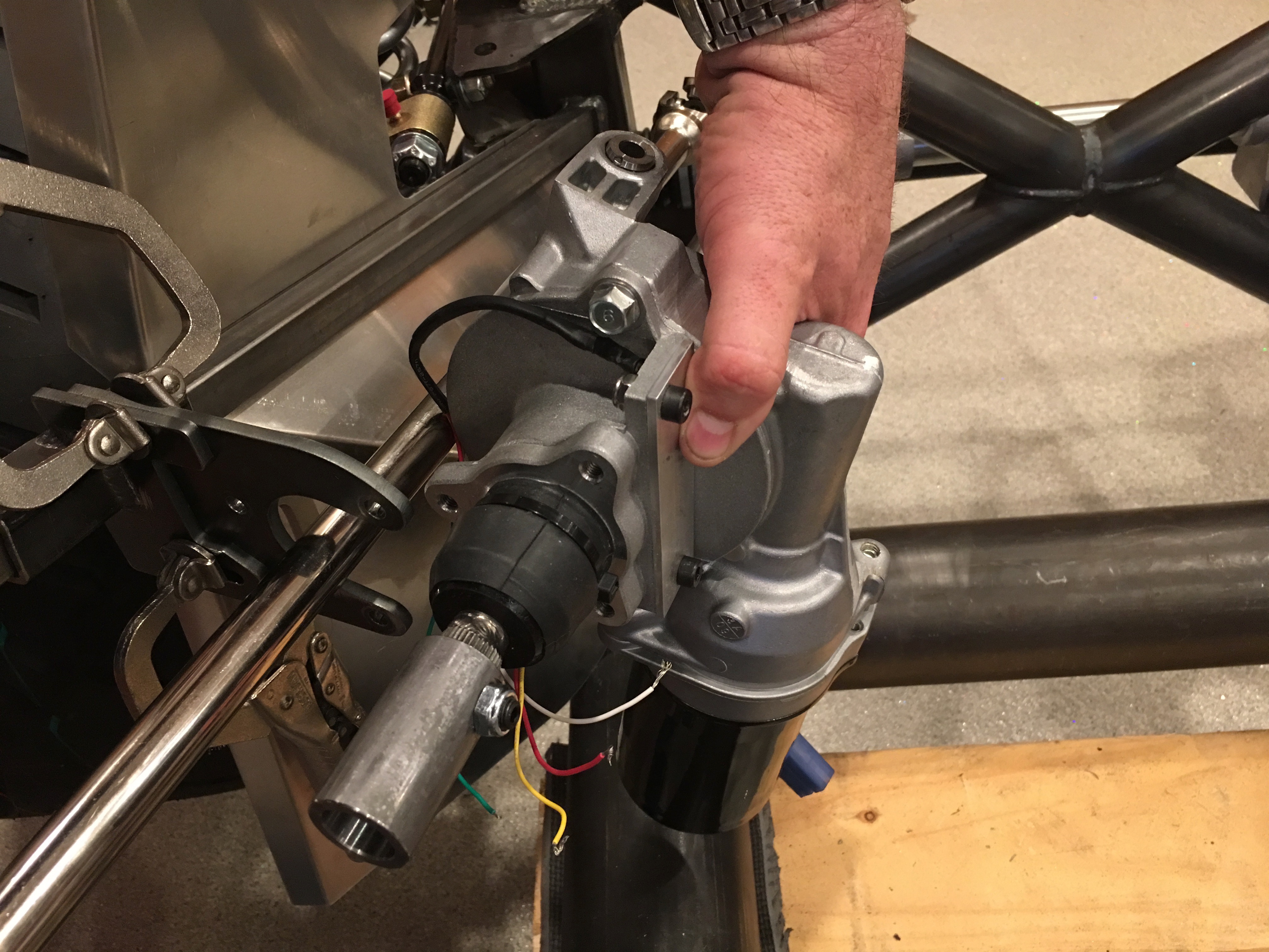
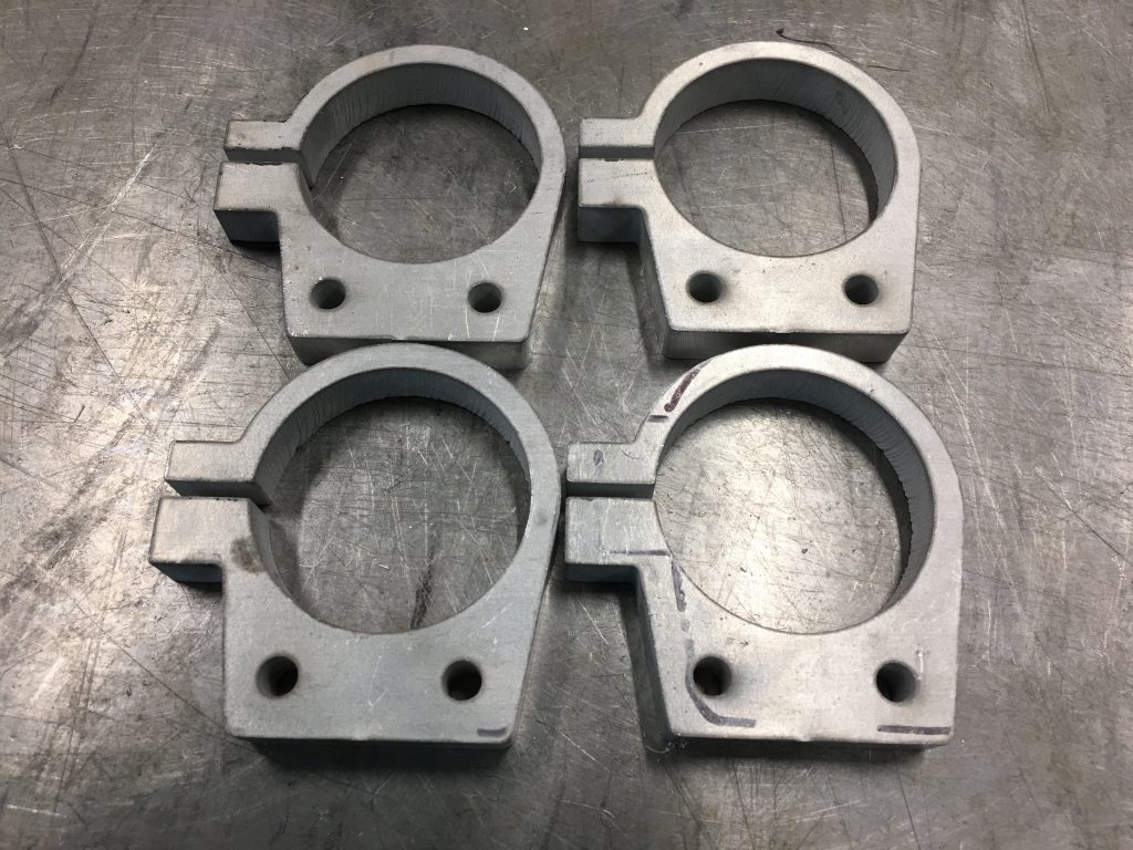
After finishing up the brake fitting brackets, I loaded up the cut path for the bracket I designed to hold the remote strut reservoirs. I’m cutting these out of a piece of 1/2″ 6061 aluminum.

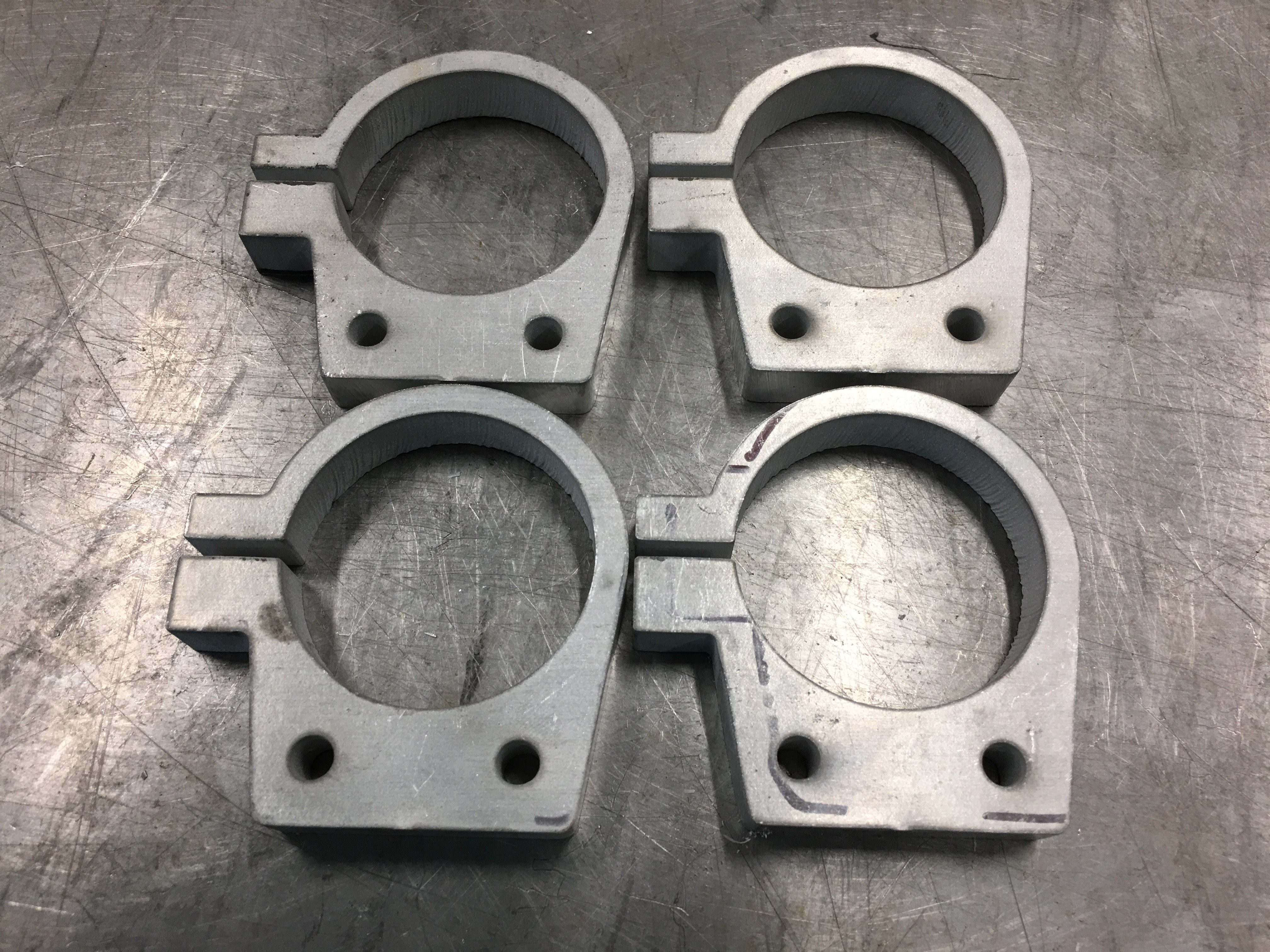
I’m glad I did the brake fitting brackets first since I had plenty of extra steel and could afford to make a couple of mistakes (as I did). For the reservoir brackets, I only had a big enough piece of aluminum to cut the four I need. Fortunately, everything worked perfectly and every piece turned out great.

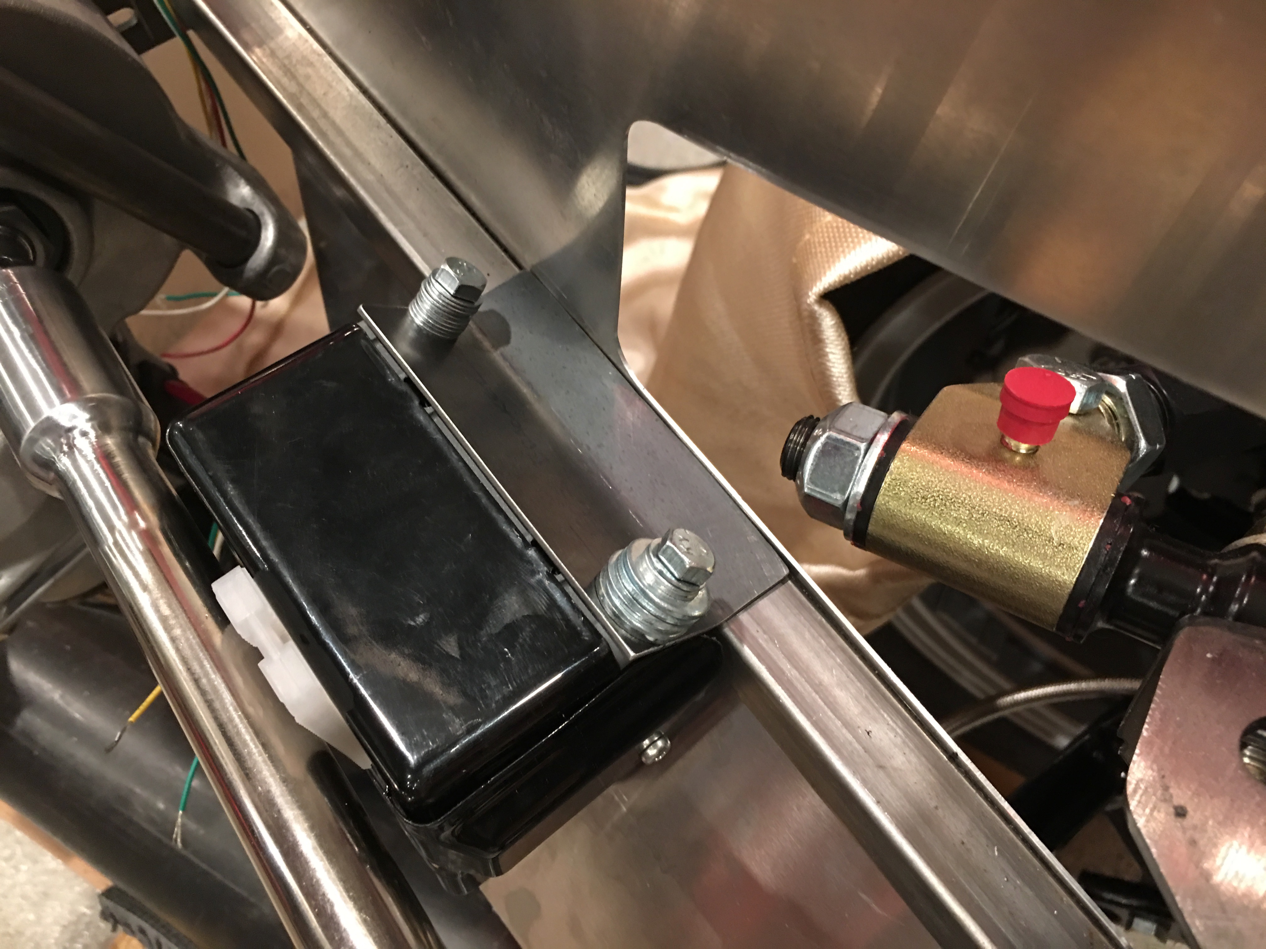
I designed these with a tab on the left that I can use to clamp the bracket tight around the reservoirs. I also cut a couple of 1/4″ holes in these so that they can bolt to a piece of angle steel that I will weld to the chassis.

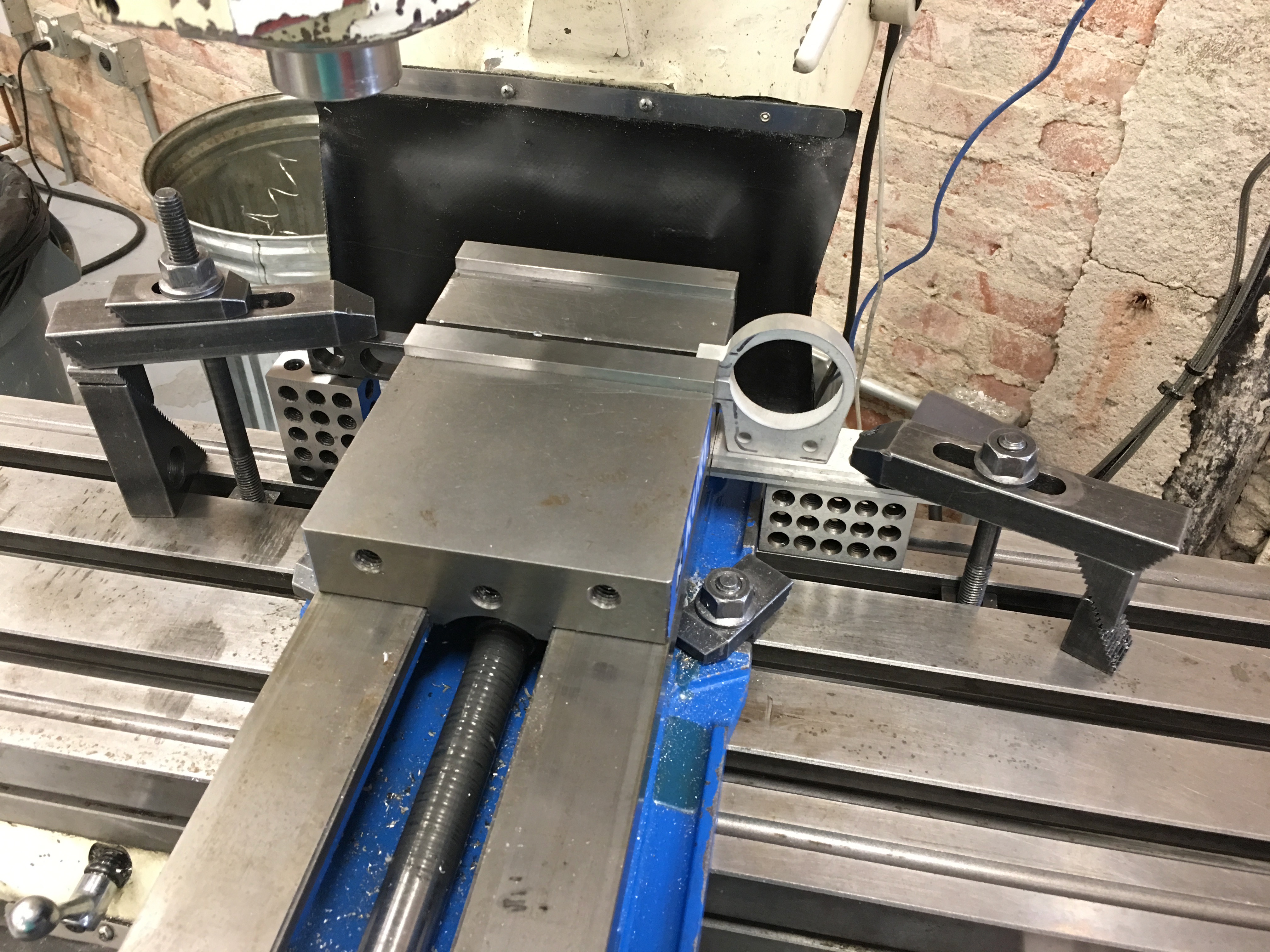
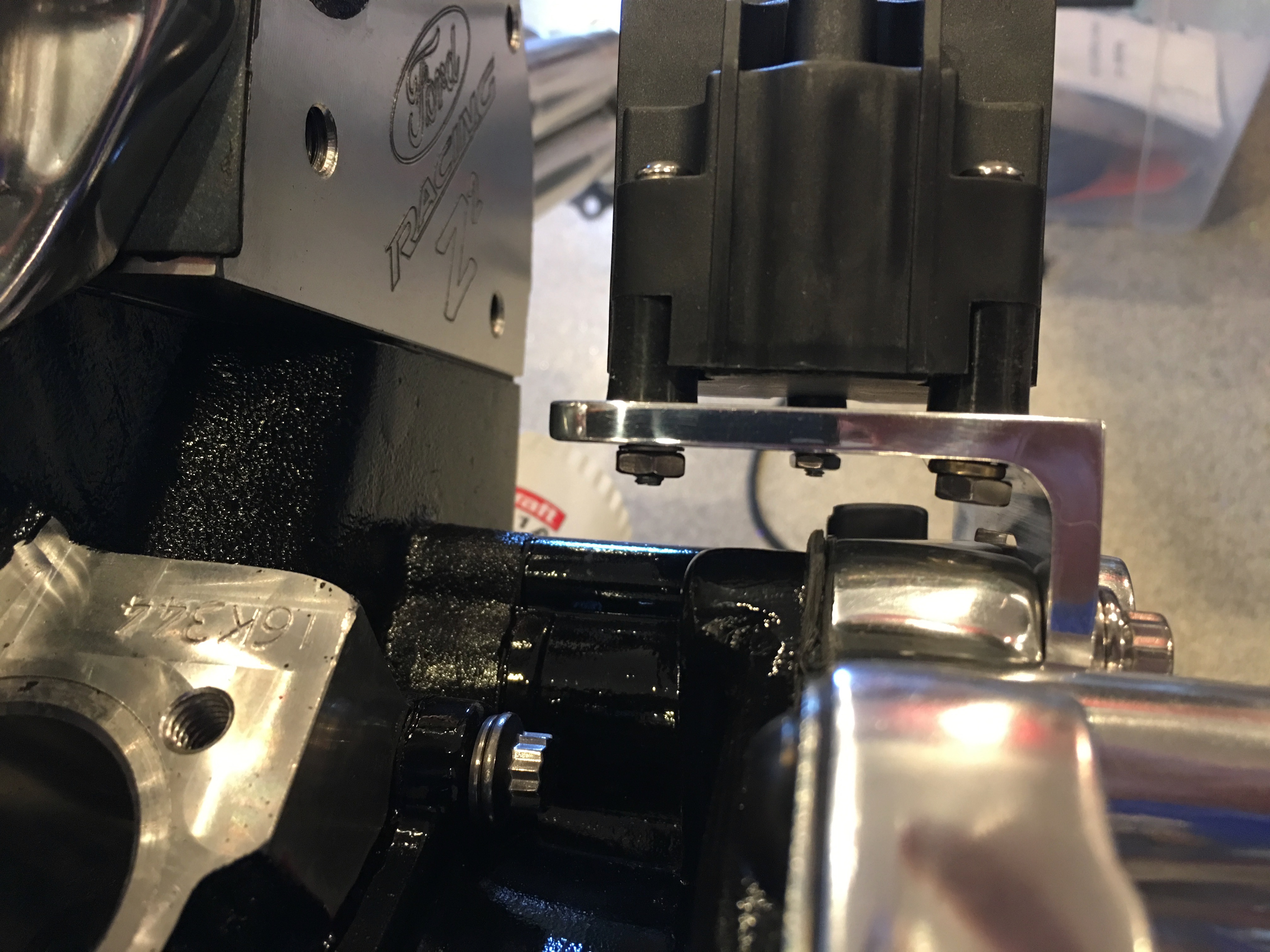
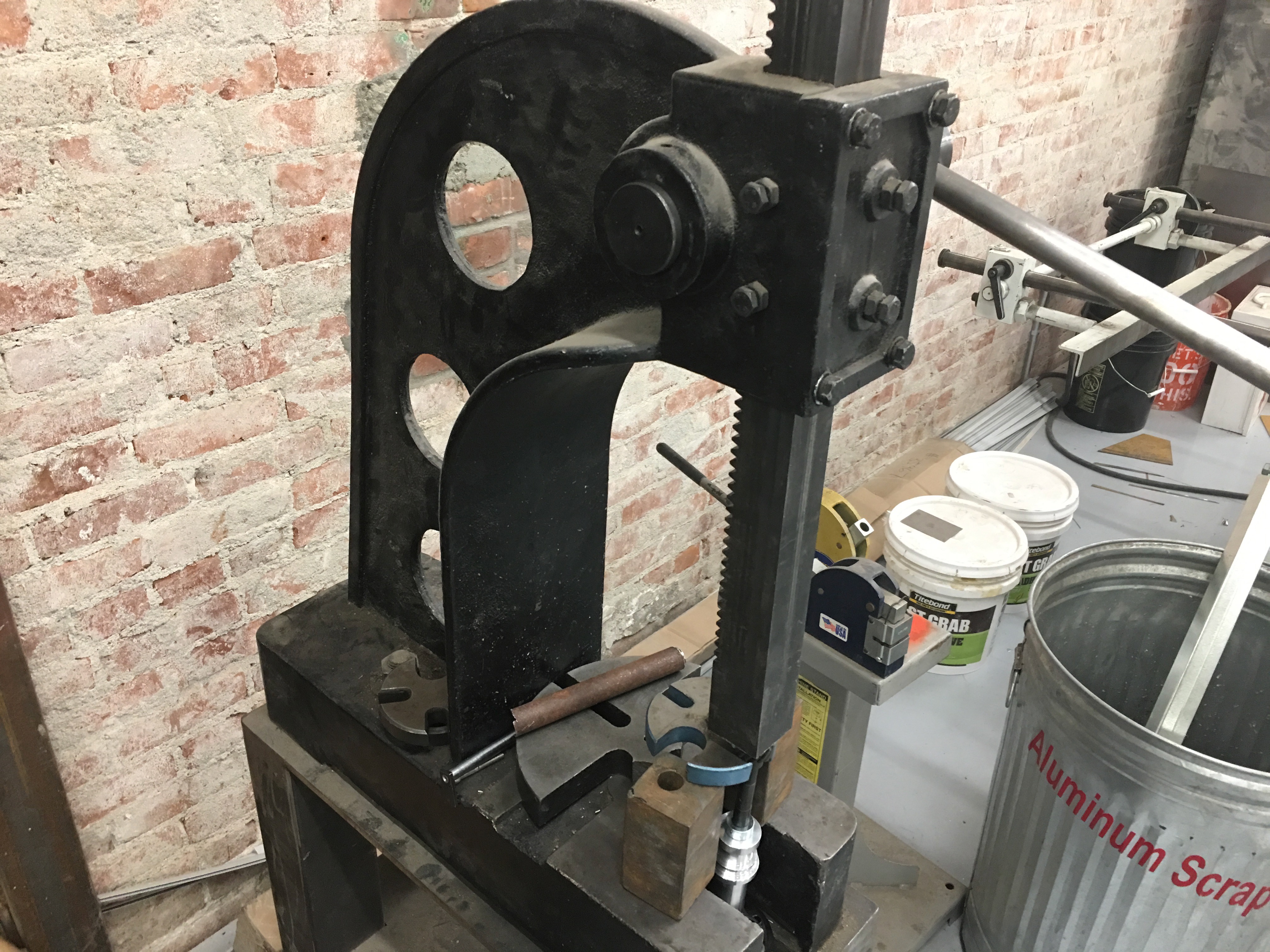
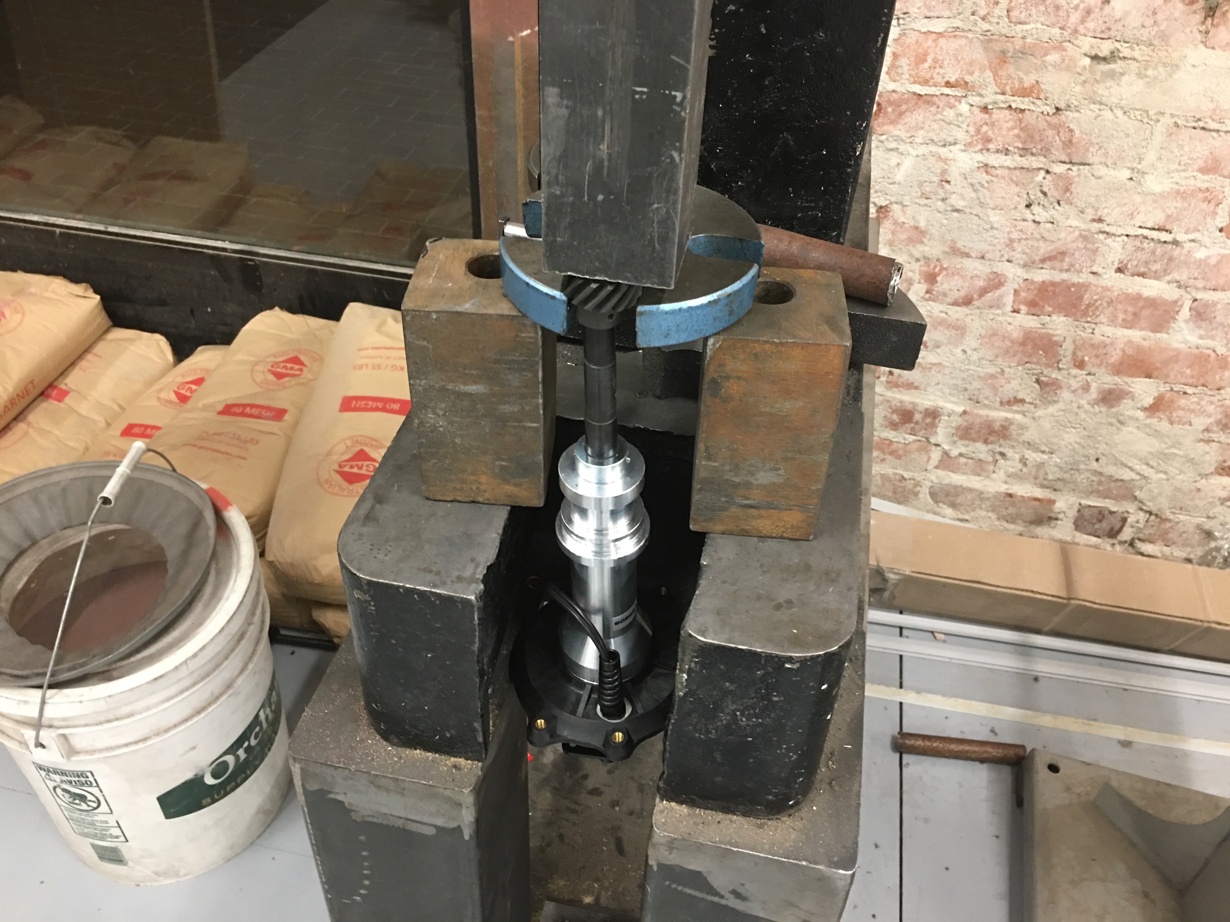
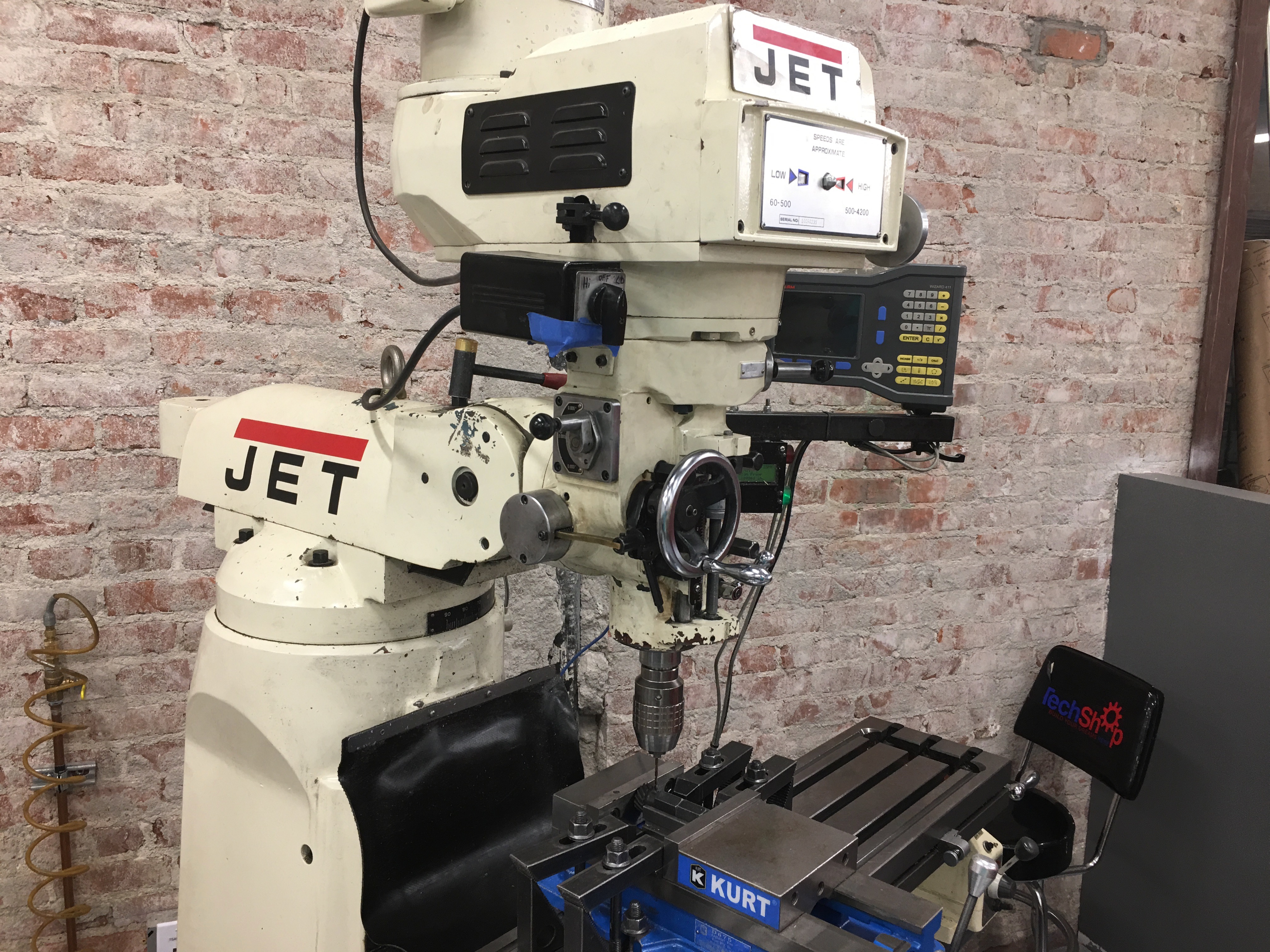
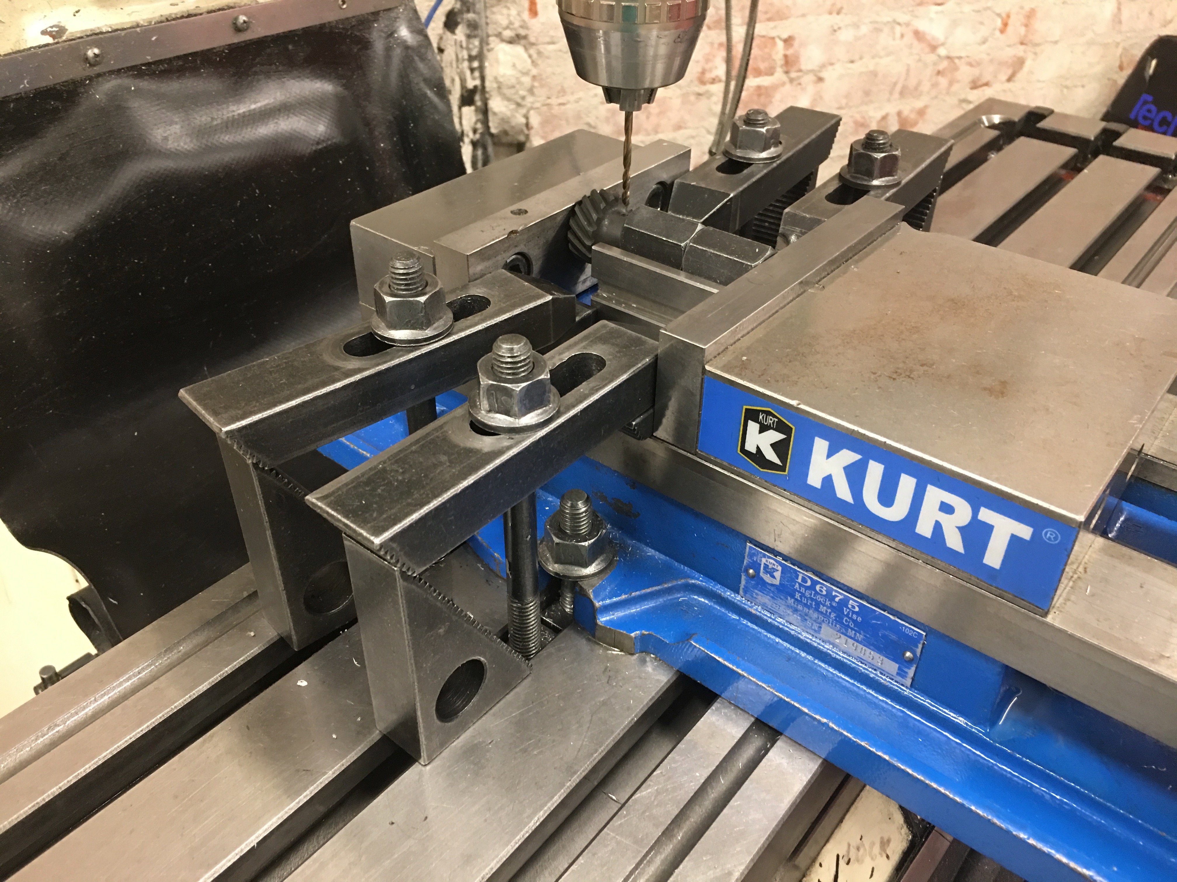
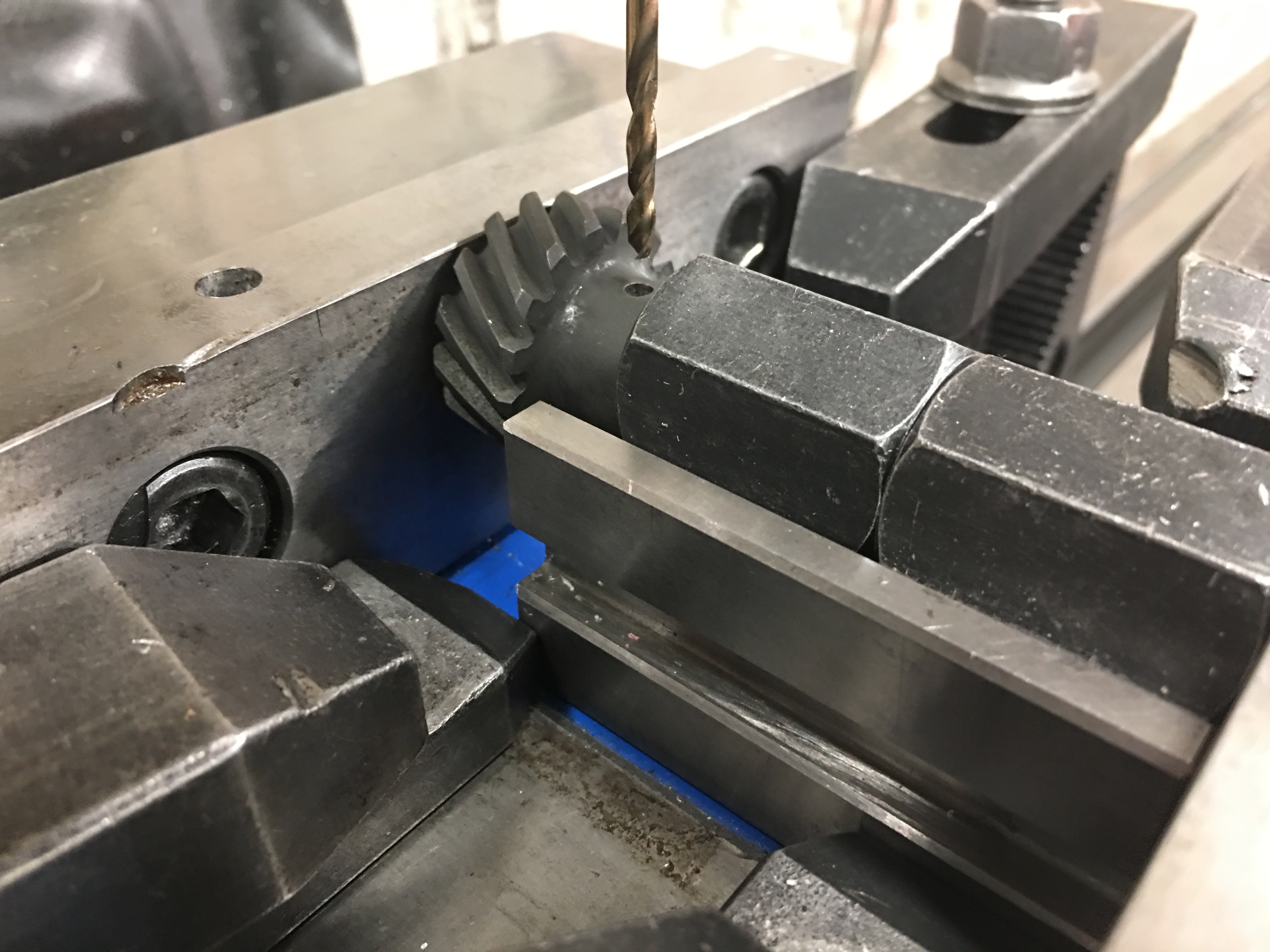
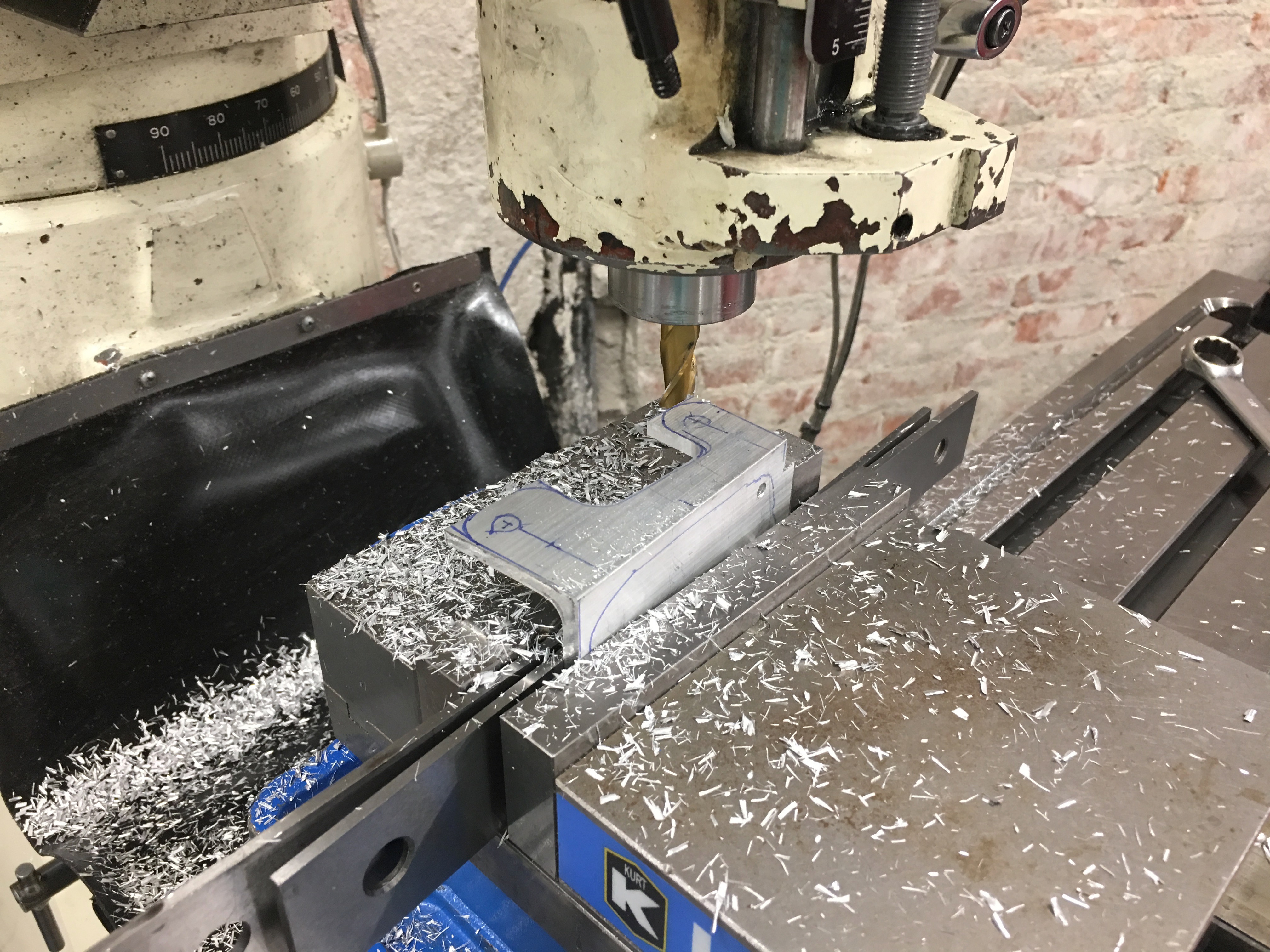
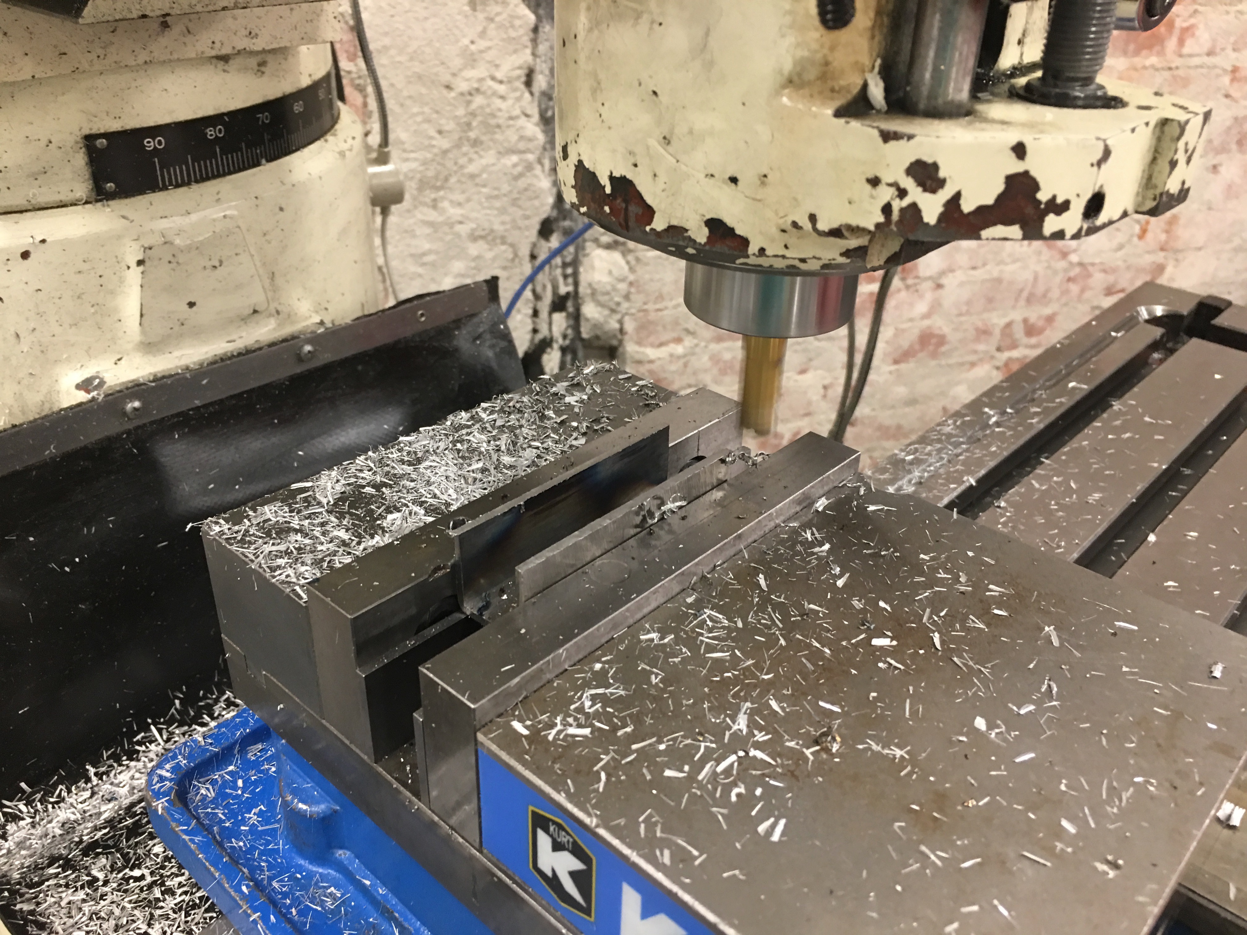
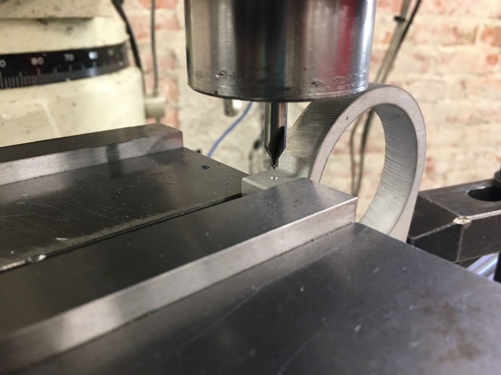
I needed to use several tools to drill the holes in the tabs, so I set up a couple of positioning fixtures to assure every piece is clamped in precisely the same location. The part sits on the fixture on the right to align it with the bed; this assures the hole is exactly perpendicular to the tabs. The fixture on the left provides a hard stop to precisely position the part in the X axis (along the bed). The Y location is fixed by the back of the vise which doesn’t move. The vise clamps both the upper and lower portions of the tabs so that there is no movement in the tabs during machining.

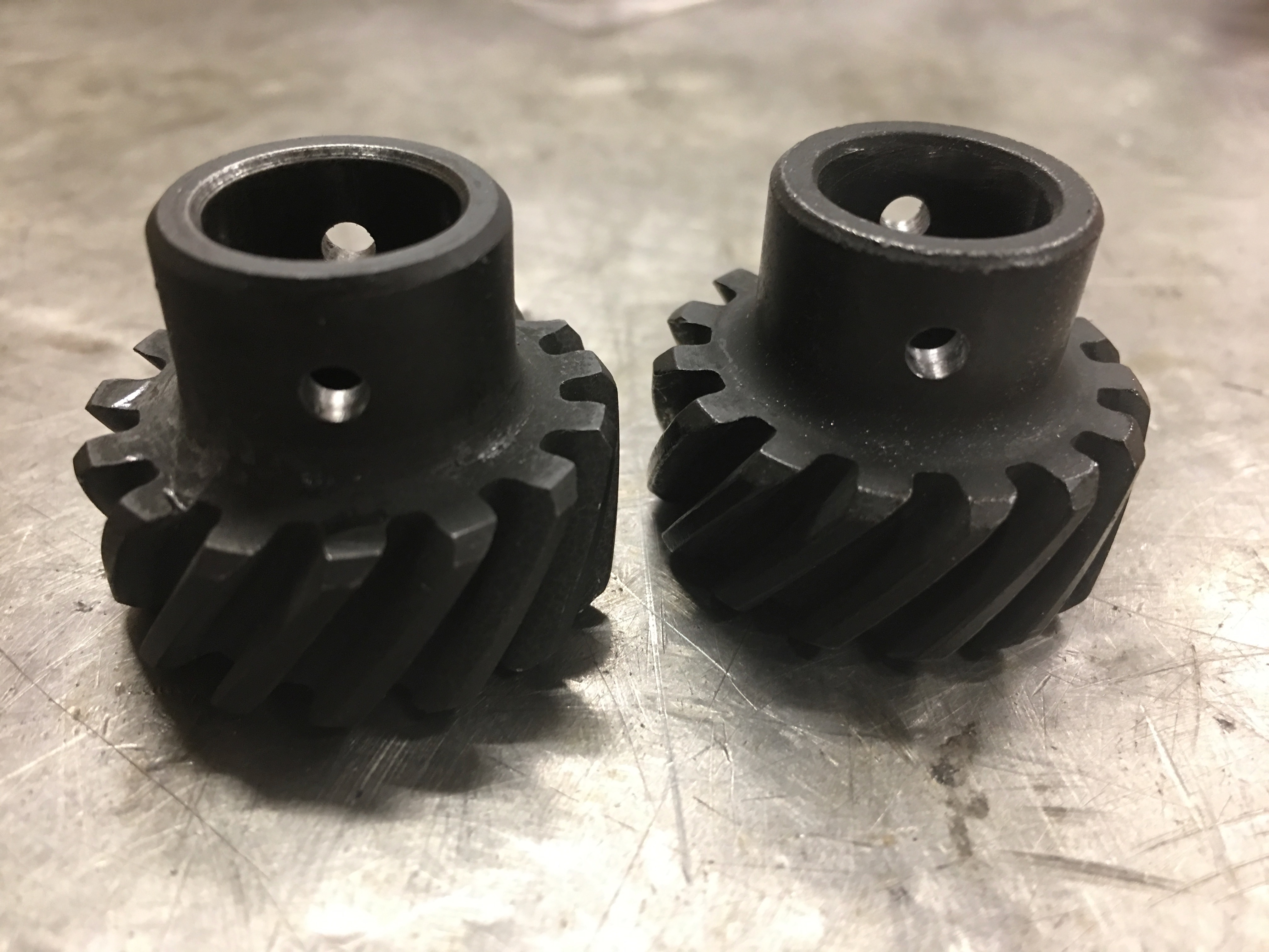
I used a center drill to create a small pilot hole in the center of the tab. I then drilled through both parts of the tab with a #7 bit and then through the upper part of the tab with a 1/4″ bit.

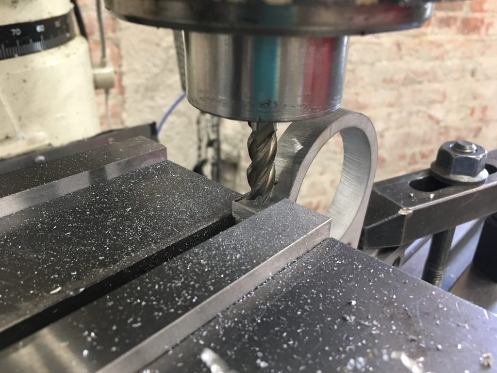
Afterward, I use a 3/8″ end mill to create a recess 0.235″ deep.

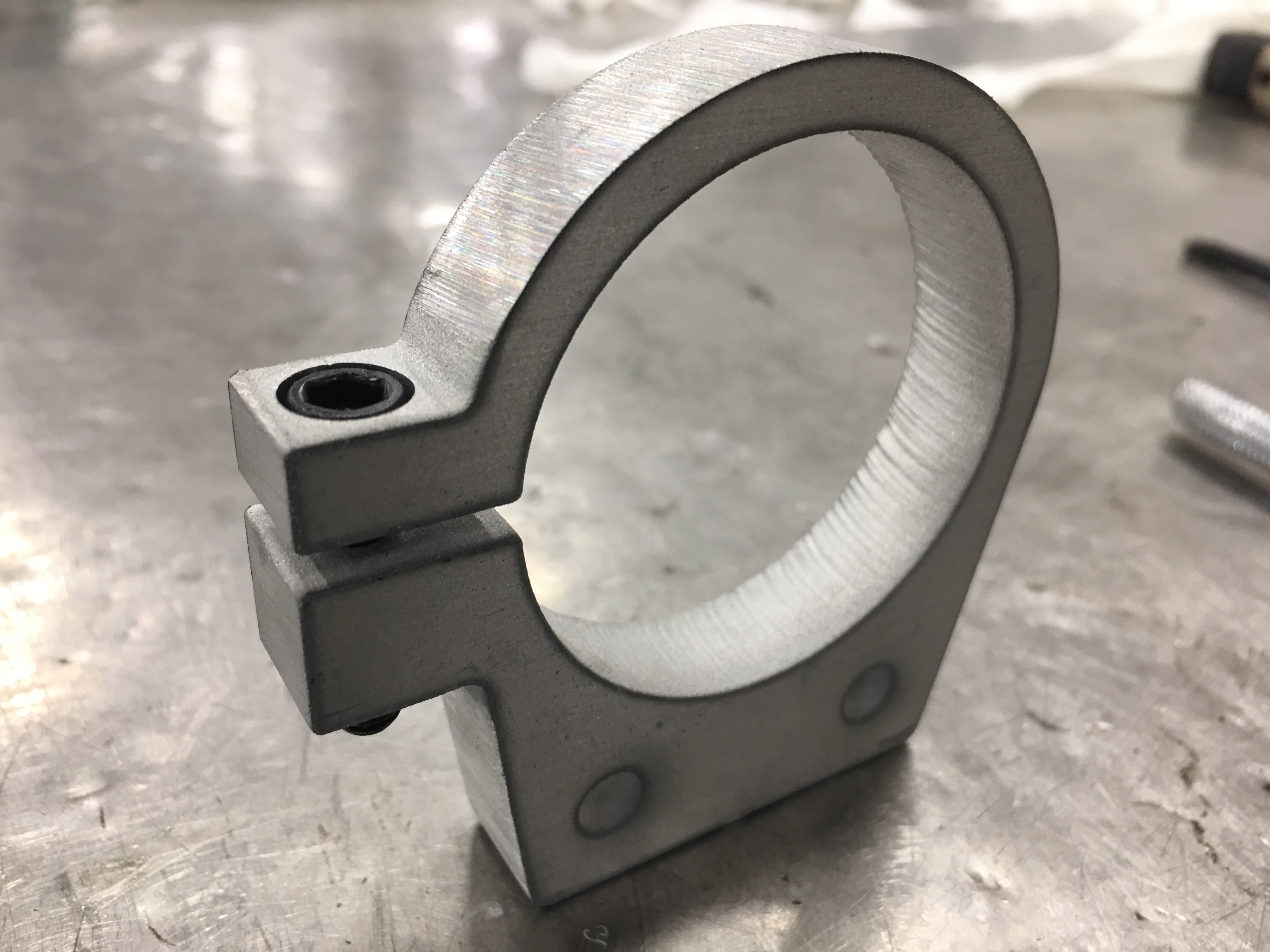
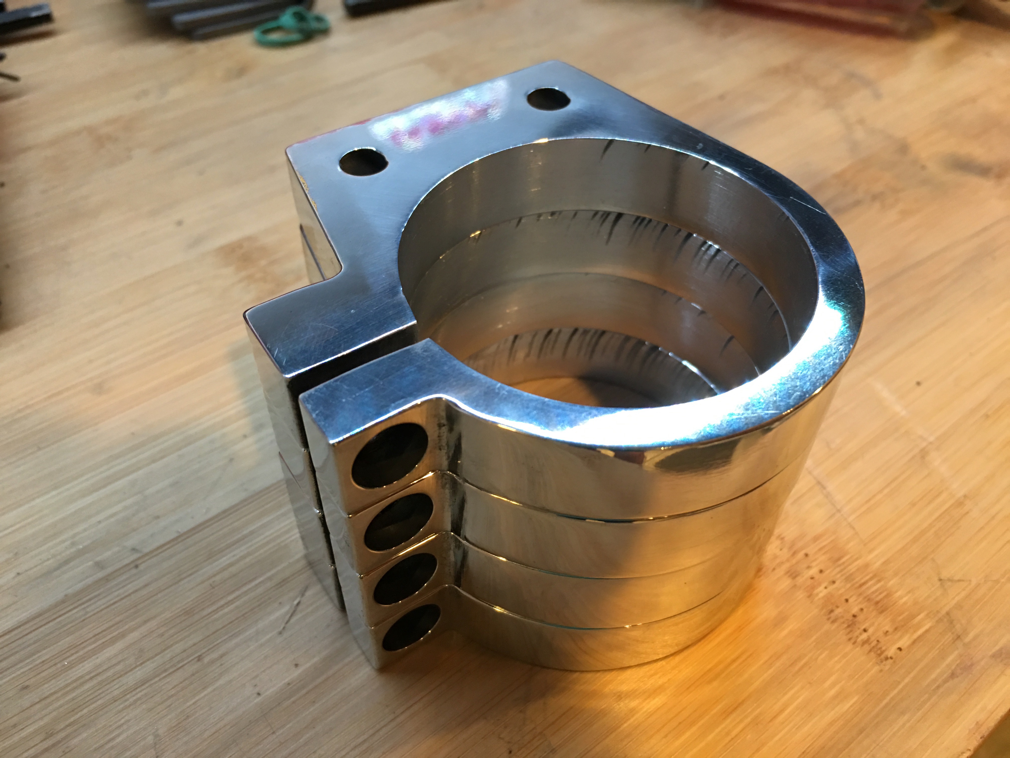
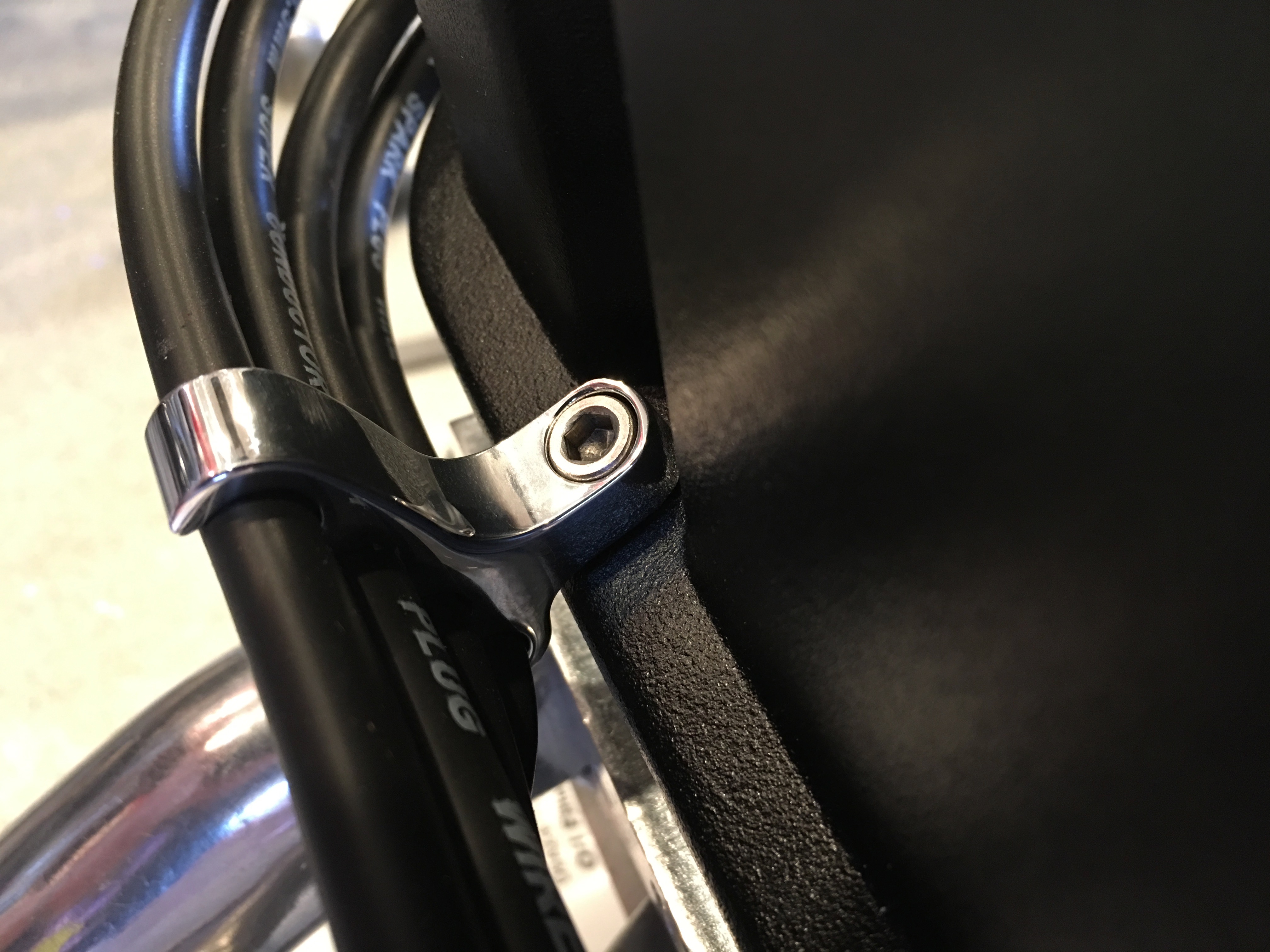
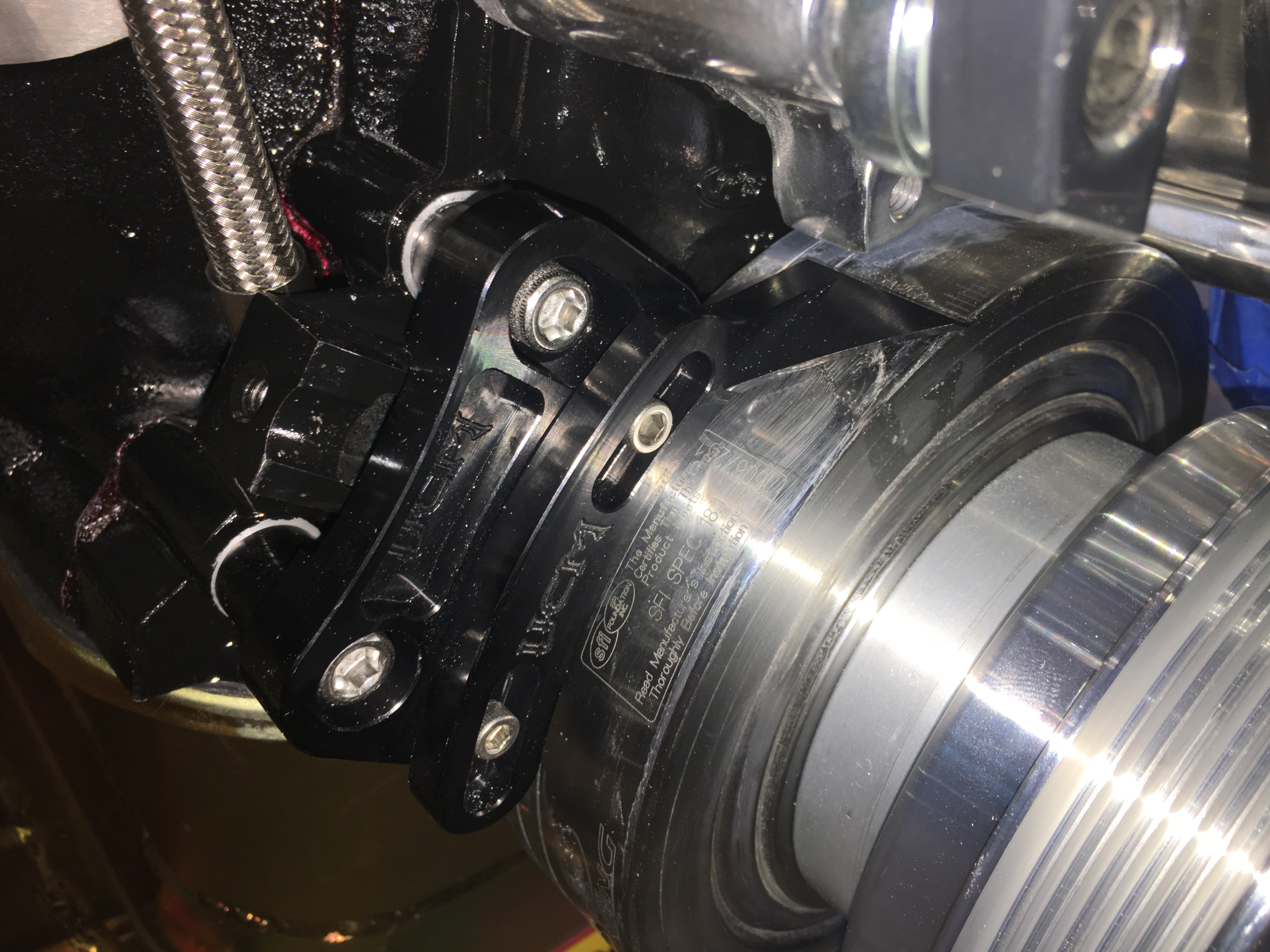
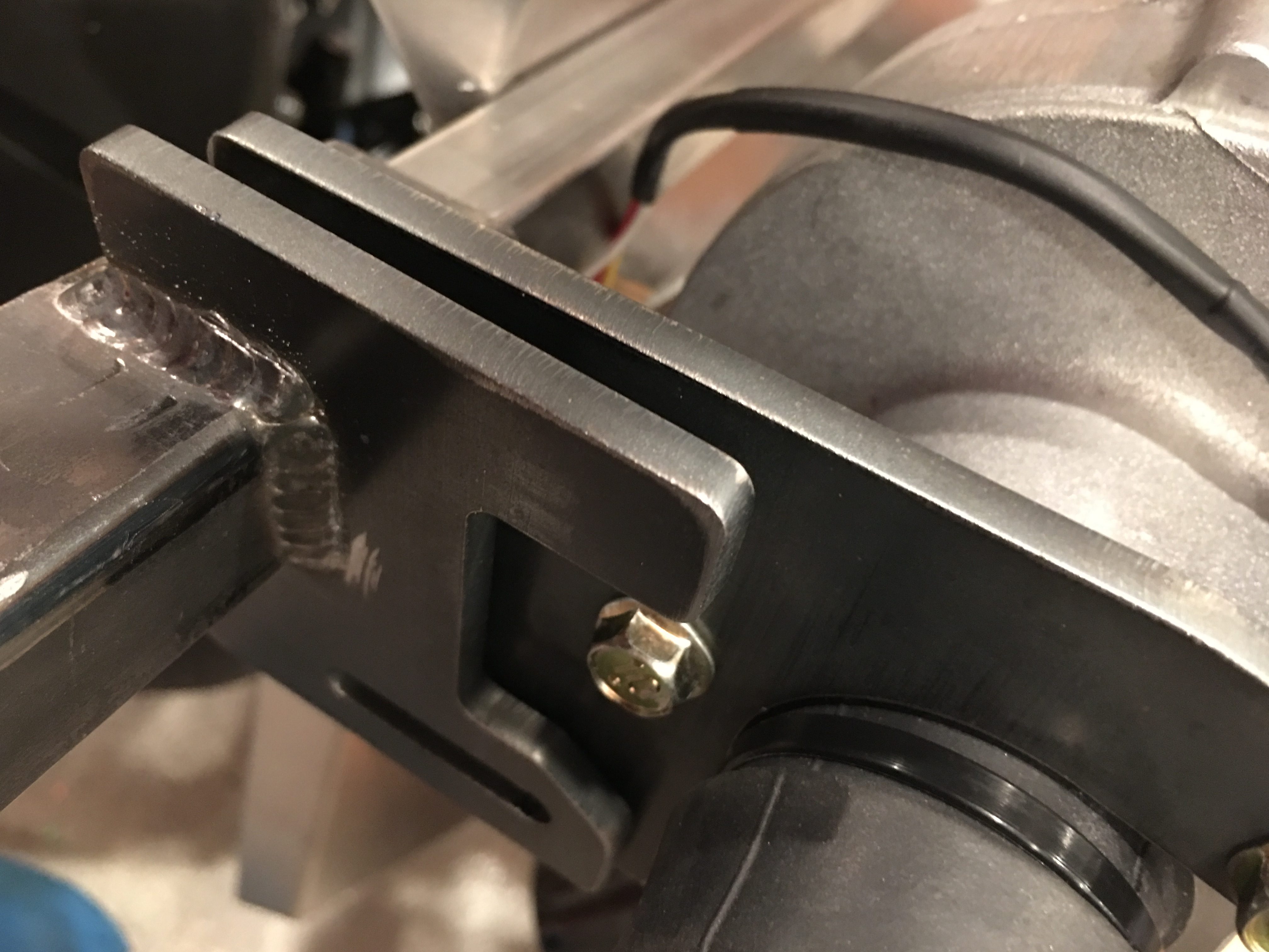
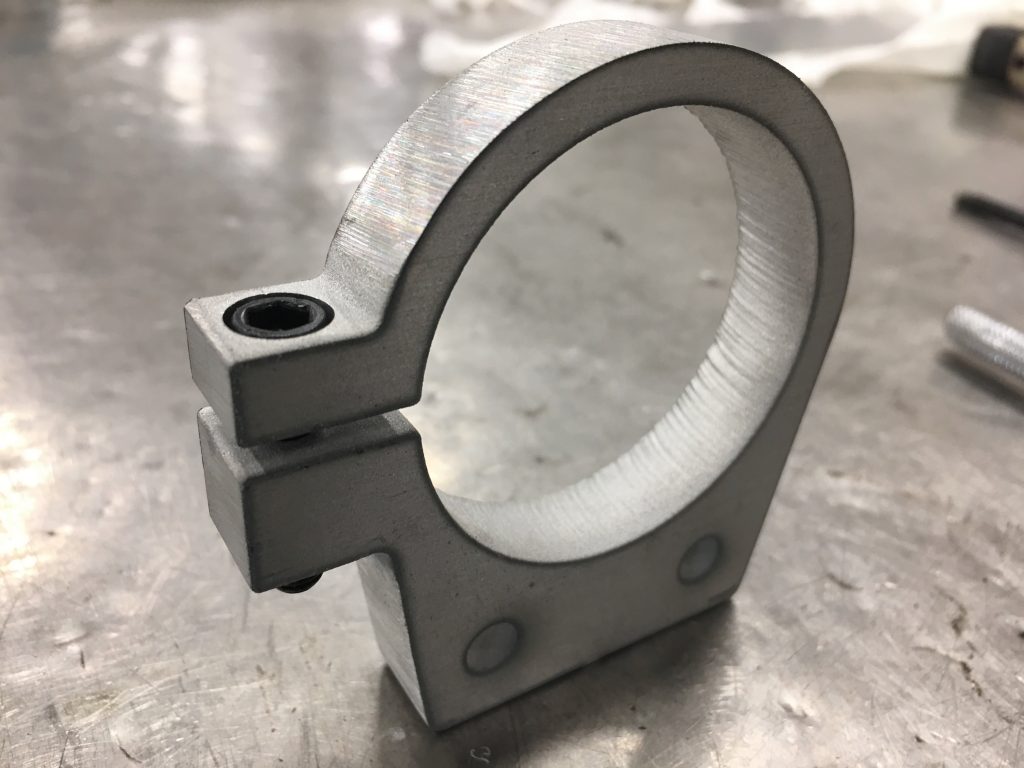
After threading the lower part of the tab with a 1/4-20 tap, I test fit a 1″ socket head bolt. The socket head bolt fits perfectly in the recess and is flush with the top of the tab. The 1″ bolt is a little long, so I’ll probably use a 3/4″ stainless bolt for the final install.

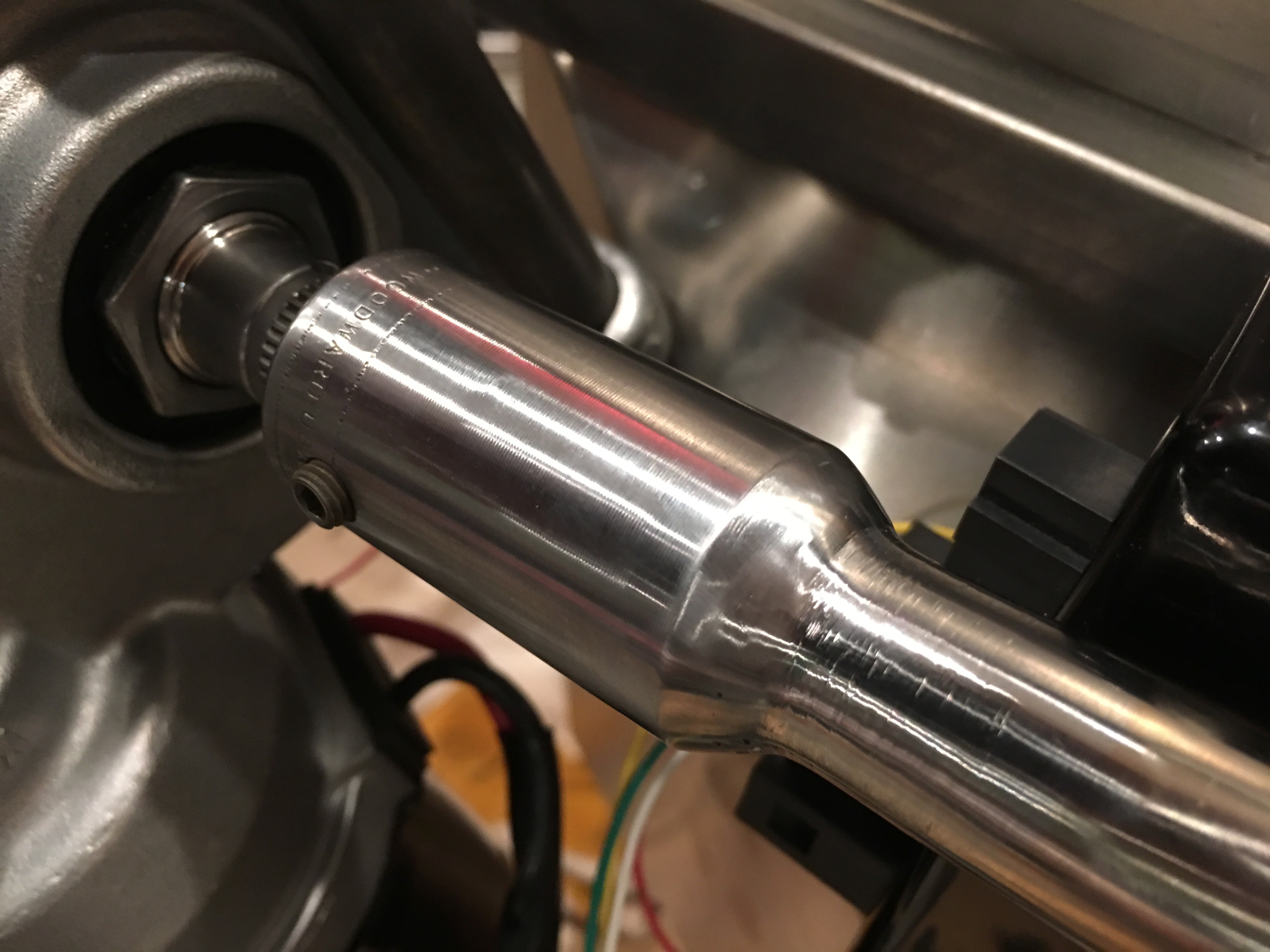
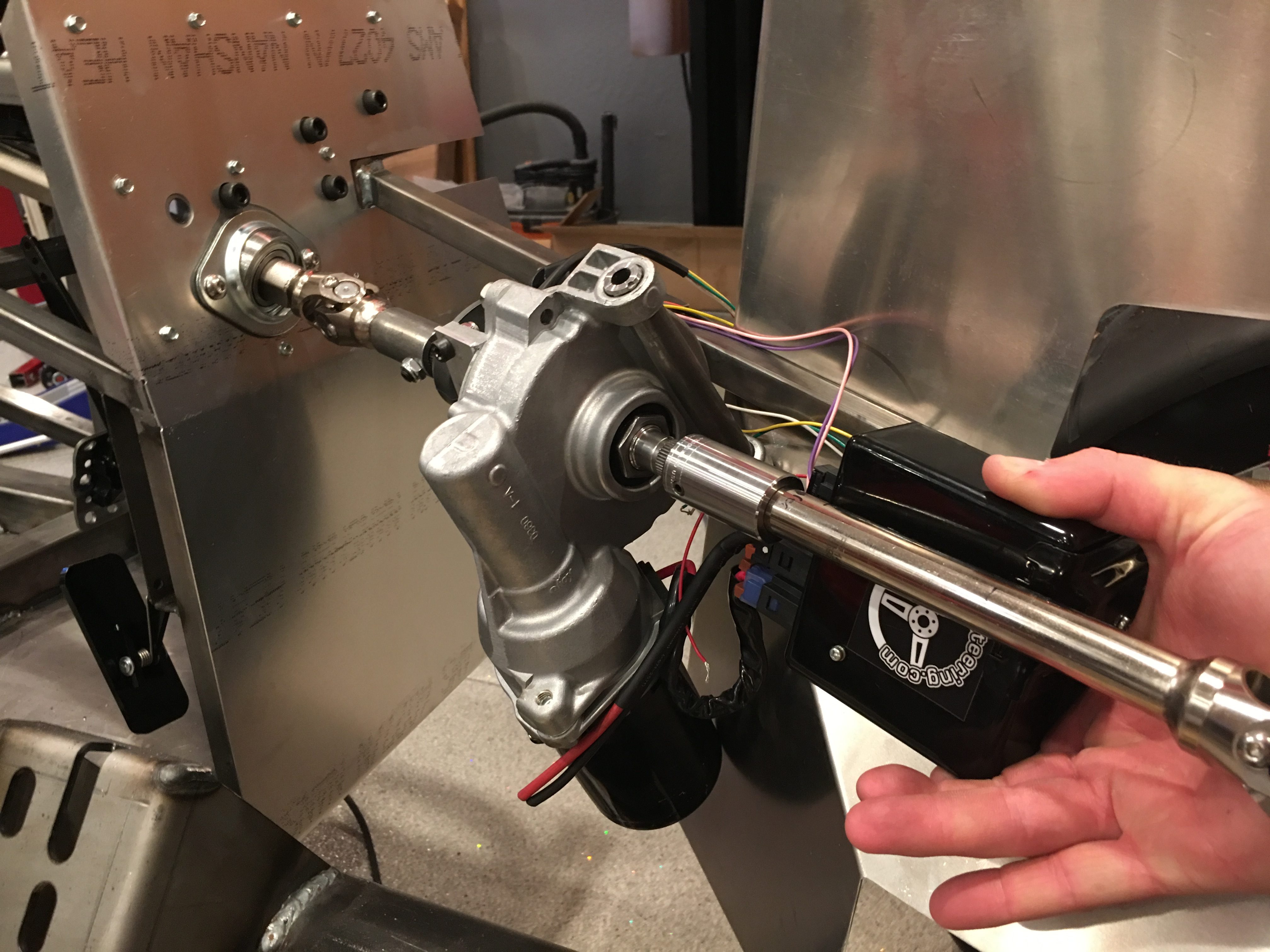
I sanded the edges smooth and used a drum sander to smooth out the inside of the hole until it’s a slip fit over the reservoir. Afterward, I polished the brackets until they are nearly a mirror finish.

The brackets hold the reservoirs perfectly. They slide over the reservoirs with almost no play and clamp tight with only about 1/2 turn on the bolt.

Fit Fuel Injection System

Our FiTech Fuel Injection system showed up today. We had been planning on installing FiTech’s Go EFI 4 – 600 HP unit which should handle more horsepower than our engine should make. The next unit up is the Go EFI 4 – 600 HP – Power Adder which supports nitrous and superchargers. Even though we’re never planning on adding either of those, there are a couple of features of the PA unit which are appealing. First, the PA unit has an advanced mode on the handheld controller and can additionally be tuned with a laptop. This should give us a lot more flexibility to tune the engine for optimum performance. Second, the PA unit can control two separate radiator fans with different activation temperatures. With the amount of heat this engine will generate, I think this might be valuable.

There are two ports at the front of the intake manifold that can hold the temperature sensor. This one only samples the coolant temperature of the coolant returning from the left bank of cylinders; the other samples both banks. I think I’ll end up with two sensors; one connected to the FiTech unit and the other connected to the dash gauge. I don’t know how much it matters which goes where, but I’m going to start with this configuration.

Since we have an air-gap intake manifold, I ran the wires under the intake runners and coolant passage. I also zip-tied the wire to the side of the sensor to eliminate strain where the wires enter the connector.

The wire comes out on the side between the runners for cylinders 3 and 4. All of the wire harnesses here will be secured with adel clamps once I have all of the wire routing figured out.

Replacing Headers

The 351W headers from Factory Five leave a lot to be desired.

  • They’re mild steel, so even with the ceramic coating on the outside, they will rust from the inside out.
  • They’re only 1.75″ pipes which is fine for a 351W, but really not enough for the 427.
  • They are four separate pipes all the way down to the square flange where they mate to the side pipes. With an EFI system, you have to install the O2 sensor after the four pipes merge so that you’re sampling one whole bank of cylinders. That means the O2 sensor would have to be installed on the side pipes where it will show.
  • They’re not mandrel bent, so there are fairly deep tooling marks all over the pipes which makes them look like shit.

After a bit of research, we’re going to go with a set of custom headers from GP Headers; they’re better in every way.

  • They’re made from 304 Stainless for maximum corrosion protection and long life.
  • We ordered them with 1 7/8″ pipes to allow the 427 to breathe a bit easier.
  • As you can see in the picture below (from a Coyote engine, but similar design), they have a double collector which allows the O2 sensor to be mounted inside the engine compartment.
  • They’re beautiful! Ours will additionally be ceramic coated for heat and appearance reasons.

These are substantially more money than the FFR versions (nearly 3x the cost), but I think they’re absolutely worth it.

Fuel Tank and Steering Rack

We’re planning on running a FiTech EFI on our engine. The best way to set up an EFI system is an in-tank fuel pump since you really don’t want high-pressure pumps to pull fuel and it’s much easier for an external pump to lose its prime and cause the engine to die. I had planned on using FiTech’s new HyFuel in-tank retrofit pump, but the OEM tank from FFR is not ideal for this pump. The pump needs to mount on a fairly flat spot on the tank, but you really want the pickup to sit in the baffled part of the tank. Unfortunately, the baffle is pretty small in this tank and there is no flat spot above the baffle that will work without extensive modification to the tank.

After a bit of research, I’ve decided to ditch the OEM tank and I’ve ordered a Boyd Welding aluminum tank with built-in Aeromotive 340 Stealth pump. This pump will work fine with the FiTech EFI unit and is already installed for less than it would cost to buy the pump separately.

I got back to wrapping up the steering linkage. Unfortunately, I realized that I installed the steering arms upside down way back when I assembled the front spindles. Even more unfortunately, they can’t be removed without completely removing the spindle from the control arms. I purchased a ball joint separator and removed the spindles. Since I had them apart, I went ahead and swapped the ball joint boots with the ones I purchased from Energy Suspension.

Here’s the lower boot (highly deformed since the suspension is unloaded).

Here’s the upper boot (also fairly deformed). These are made from polyurethane and are quite a bit tougher than the ones that came off the ball joints. I’m glad I replaced these since both upper boots had already torn from the pressure on them when the suspension is unloaded.

I adjusted the length of the tie rods until the wheels are roughly aligned. This is probably as close as I can get this until the car is sitting on its tires at roughly the driving weight.

Spark Plug Wires and Steering Linkage

I temporarily fit the headers so that I could route the spark plug wires. I’m using the MSD multi-angle boot spark plug wires so that I can adjust the boots for the best clearance. I’ll do the final tweaking of the boot angles and wire position once the distributor is installed and all of the wires are cut to length.

I’m using some billet aluminum wire supports from Billet Specialties.

They replace the valve cover bolts and are a solid piece (unlike many of the cheaper wire supports). They’re sold in packs of two with between 1-4 spots for wires. I needed the following:

  • 3x 4 position
  • 1x 3 position
  • 2x 2 position
  • 1x 1 position

I also further trimmed the ignition coil bracket I made and polished it up before mounting it to the water pump. I needed to order some custom length bolts to mount this since the old bolts were too short.

There’s plenty of clearance between the bolts that attach the coil and the top of the water pump. The right most bolt looks like it’s not engaged sufficiently, but the stud is flush with the bottom of the nut. Given the low load on these, that is sufficient.

I pulled off the F panel on the left side and welded the brackets on securely. I think the steering linkage is installed for the last time before we drive the car.

Steering Linkage, Chassis Mods and Timing Pointer

I installed the EPS brackets and tacked the two pieces of the bracket together and tacked it to the chassis. I’ll finish welding this after pulling the steering linkage off and unscrewing the aluminum F panel.

With the steering linking all bolted into its final location, I tacked the upper coupler to the steering shaft.

I also tacked the lower coupler.

I then TIG welded the couplers all the way around and ground everything smooth. Here’s the upper coupler.

And here’s the lower coupler. I may have these chromed after the chassis comes apart for finishing.

While I was at the TechShop, I fabbed up a piece of 16ga steel to attach the EPS controller to the chassis. The bolts are metric, so the only ones I had on hand were too long. I’ll pick up the right bolts before bolting this in for good.

Since I’m relocating the parking brake, I cut off the bracket that holds the handle. I’ll have to fab up a bracket once I figure out the new location.

I also cut off the bracket that hold the parking brake cables. I really wish I had cut this off before installing the differential; it was a real challenge cutting this off while working around it.

I originally purchased a timing pointer that mounts at the 2 o’clock position, but it turns out that that would be pretty hard to see since we’re using a water pump with a driver side inlet. I replaced that with one that mounts at the 11 o’clock position, but it interferes with a bracket on the Ford timing cover. Ford confirmed that it’s unnecessary, so I cut it off with a cutoff wheel.

After touching up the paint, I installed the pointer and aligned it with the 0º mark.

Distributor Gear and Parts Fabrication

I need to swap the distributor gear to be compatible with the cam gear. After driving the roll pin out, I used the TechShop’s arbor press to press the gear off.

I had to use some scrap metal to shim the bolster plate up high enough to give me clearance to press the shaft down. I also had to remove the rotor and upper housing to allow the distributor to fit between the legs of the press.

With the old gear pressed off, I needed to drill the new gear to match. I set up a duplicating rig on the mill.

Four clamps around the side precisely locate a v-block in the vise.

The shaft of the gear sits in the groove of the v-block and is clamped against the forward face of the vise using a couple of clamping nuts. The critical reference measurement on the gear placement is from the lower face of the gear (the one clamped to the forward face of the vice), so this arrangement will make the hole the exact same distance from that face. I adjusted the table so that the 1/8″ bit would slide all the way through the old hole without any side load. I then loosened the vise and swapped in the new gear.

The new gear is on the right and the hole turned out perfect. All that’s left is to press the new gear onto the shaft and somehow figure out how to align the holes. If I can’t get the holes aligned, I can always press it on 90º off from the existing hole and drill a new hole through the shaft.

Next up is to trim the ignition coil mounting plate. After cutting it to rough size on the band saw, I mounted it in the milling machine vise. I used some shims to mount it at an angle since the mounting legs are asymmetric.

After machining and some finish sanding, I polished it up a bit on the scotchbrite wheel. After I drill the mounting holes and confirm the fit, I’ll polish this until it’s as shiny as the water pump.

Finally, I cut the electric power steering mount apart so that I can reweld it at the proper angle.

I sanded off all of the welds and cleaned up the edges.

The channel hung over the 3/4″ tubing by just over 1/8″, so I machined off the flanges to align with the face of the 3/4″ tubing when welded.

Steering and Ignition Coil

The first step in installing the electric power steering (EPS) system is to cut the steering shaft. I ended up moving the electric motor back almost as far as it could go and then taking some measurements from the engine mount to ensure I’ll have plenty of clearance.

I just started with a single cut in the shaft because this would let me adjust the motor up or down from there, but it looks like this spot will work absolutely perfectly. I really can’t go back any further because I’d hit the steering shaft u-joint and I’d interfere with the exhaust headers which exit just aft of here.

After determining everything will fit nicely, I cut the other end of the shaft and test fit everything.

The bracket that came with the system isn’t welded at the right angle to allow the motor bracket to bolt up to it. I’ll let Erik know, but I’ll probably just cut and reweld this myself.

The motor clears the F panel by over 1/8″. This bracket isn’t used in this application, so I may just cut it off.

After hunting around for a good place to mount the EPS controller, I decided to mount it to the 3/4″ tubing behind the steering shaft. There’s nearly 1/4″ of clearance between the shaft and the controller, and it’s really out of the way here. The challenge is that there are only two threaded bosses on the EPS controller and they’re at an odd angle. I need to be able to access the screws later in case the controller needs to come out. Mounting it here lets me fabricate a simple bent steel bracket and easily access the mounting screws if necessary.

I ended up deciding to mount the ignition coil to a custom bracket that will bolt to the front of the water pump. I had a piece of scrap aluminum angle, so I took some measurements and laid out the shape of the bracket.

Once I cut out the bracket, it will bolt to the front of the water pump using these two bolts. This should clear everything around it and provide a nice, short run from the coil to the distributor.

Steering and Fuel Tank

I started installing the steering system by installing the bearing block in the firewall and slipping the steering shaft up through it.

I then installed the steering rack into the front of the chassis. The brackets needed some bending to allow the mounting lugs to fit and the elongated hole on the left side (right in this picture) needed to be elongated further on the front bracket to allow the rack to slide far enough to the left to get the right bolt installed.

I installed the upper pillow block and slipped the upper steering shaft through and into the lower shaft to lock in the final position.

I ordered an electric power steering system from Erik Hansen on the FFR forum. After grinding and filing the bracket on the left to fit over the 3/4″ tube, I test fit it along with the bracket on the right until it’s roughly centered around the shaft. The instructions specify how far down the steering shaft it should be installed, but that puts the bracket quite a bit farther forward than this. Ordinarily, that wouldn’t be a problem, but the fat tire F panel will interfere with the bracket as well as the motor if I move it farther forward (I might even need to move it farther back from here)

Here’s the motor that will be installed inline with the steering shaft. I need to confirm that moving it back this much won’t cause any interference with the engine, but I think it will be fine.

I’ve been looking for a spot to mount the remote reservoirs for our quad-adjustable shocks, but I was concerned that the fuel tank will limit accessibility. I figured the easiest way to make sure was to just install the tank. Before doing so, I installed the fuel level sender in the center of the tank.

I also installed the vent at the highest point in the tank.

Finally, I installed the tank in the car.

Getting the tank up high enough to start the bolts required bending the flanges down where the tank sits against the bottom of the square tubing. Finally, I zip tied the vent tubing to the 3/4″ tubing, running it up and over to the left side of the car (though I’m not sure if this will be the final routing).