Electric and Final Fuel Lines

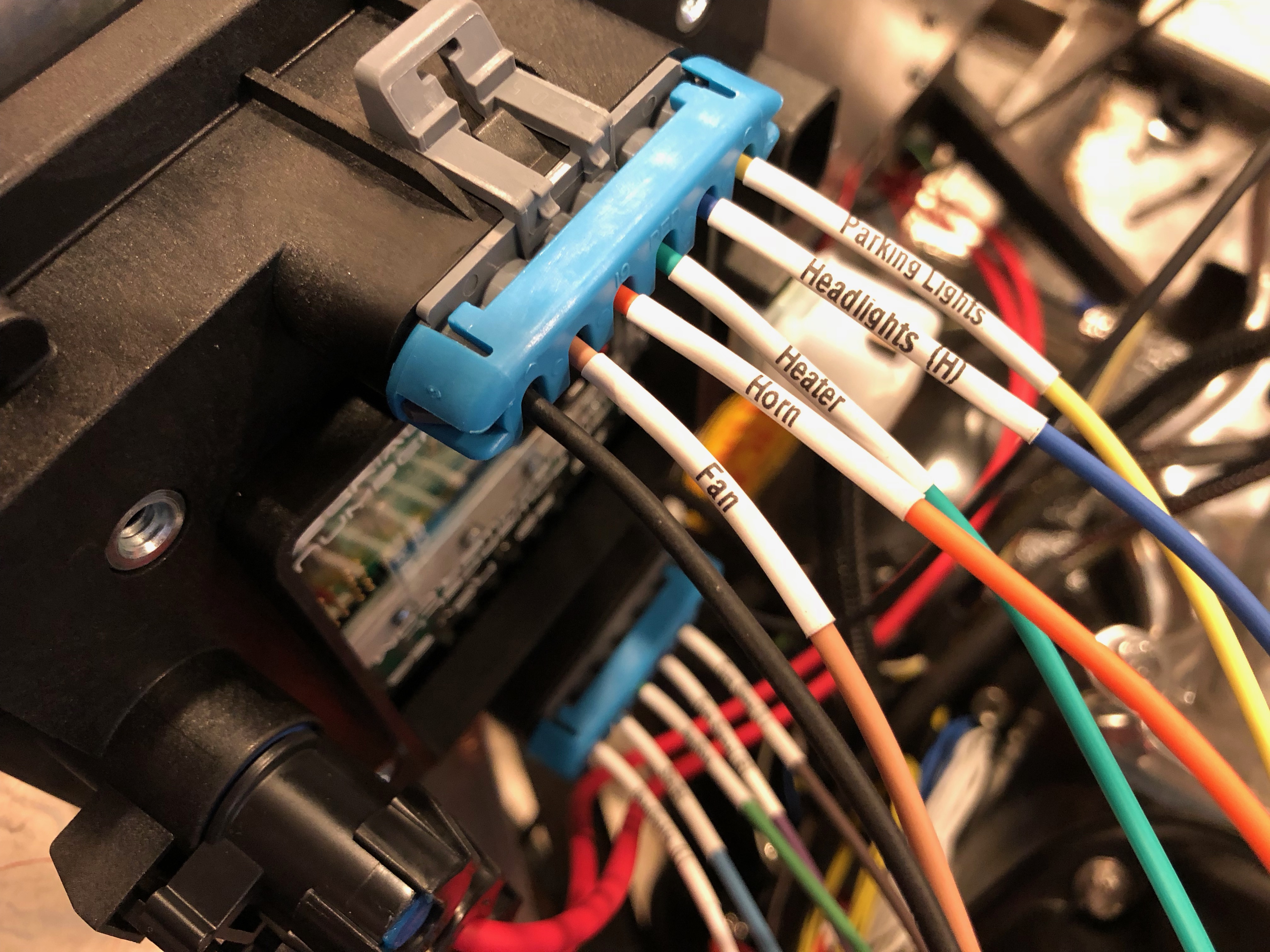
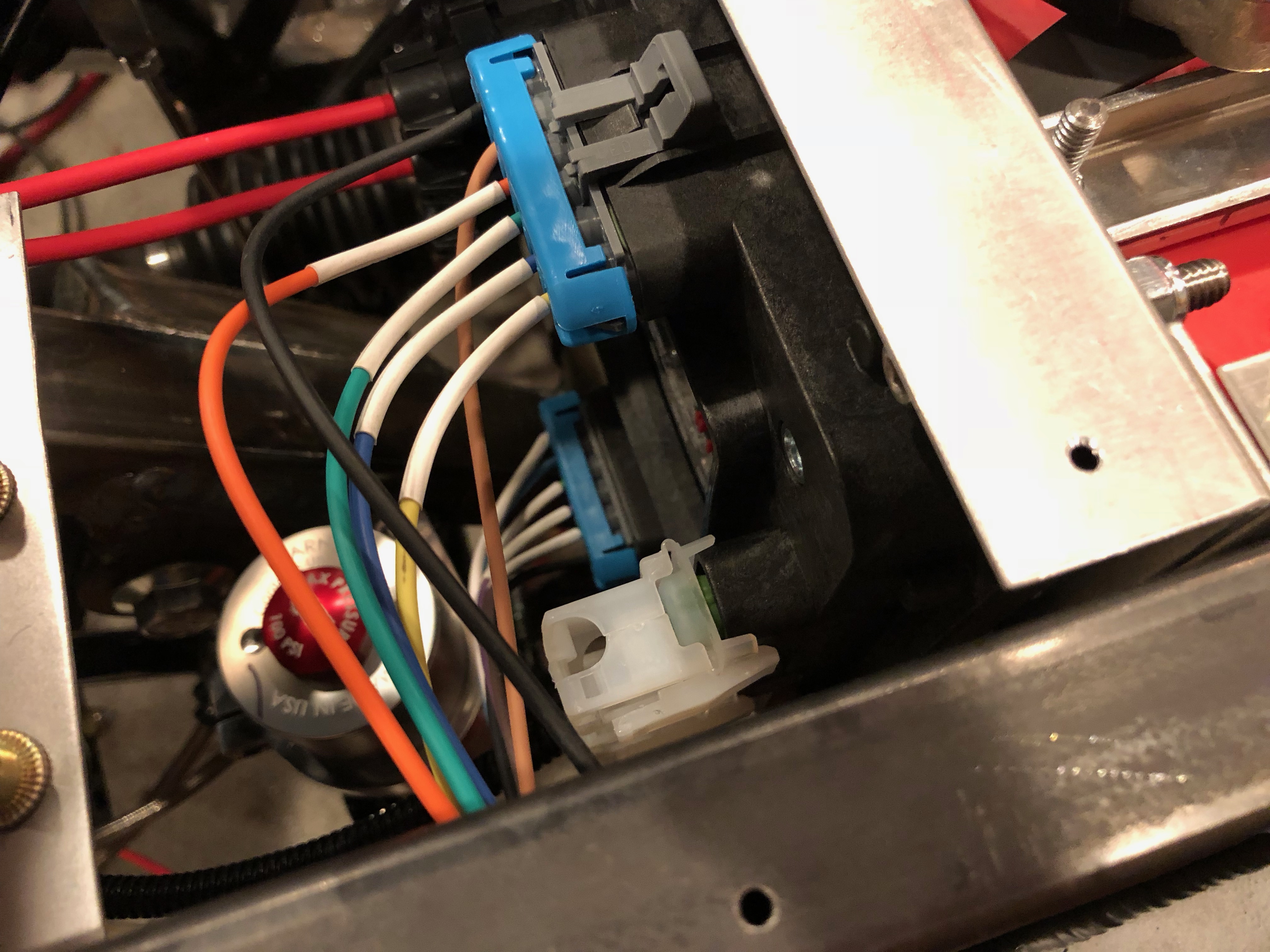
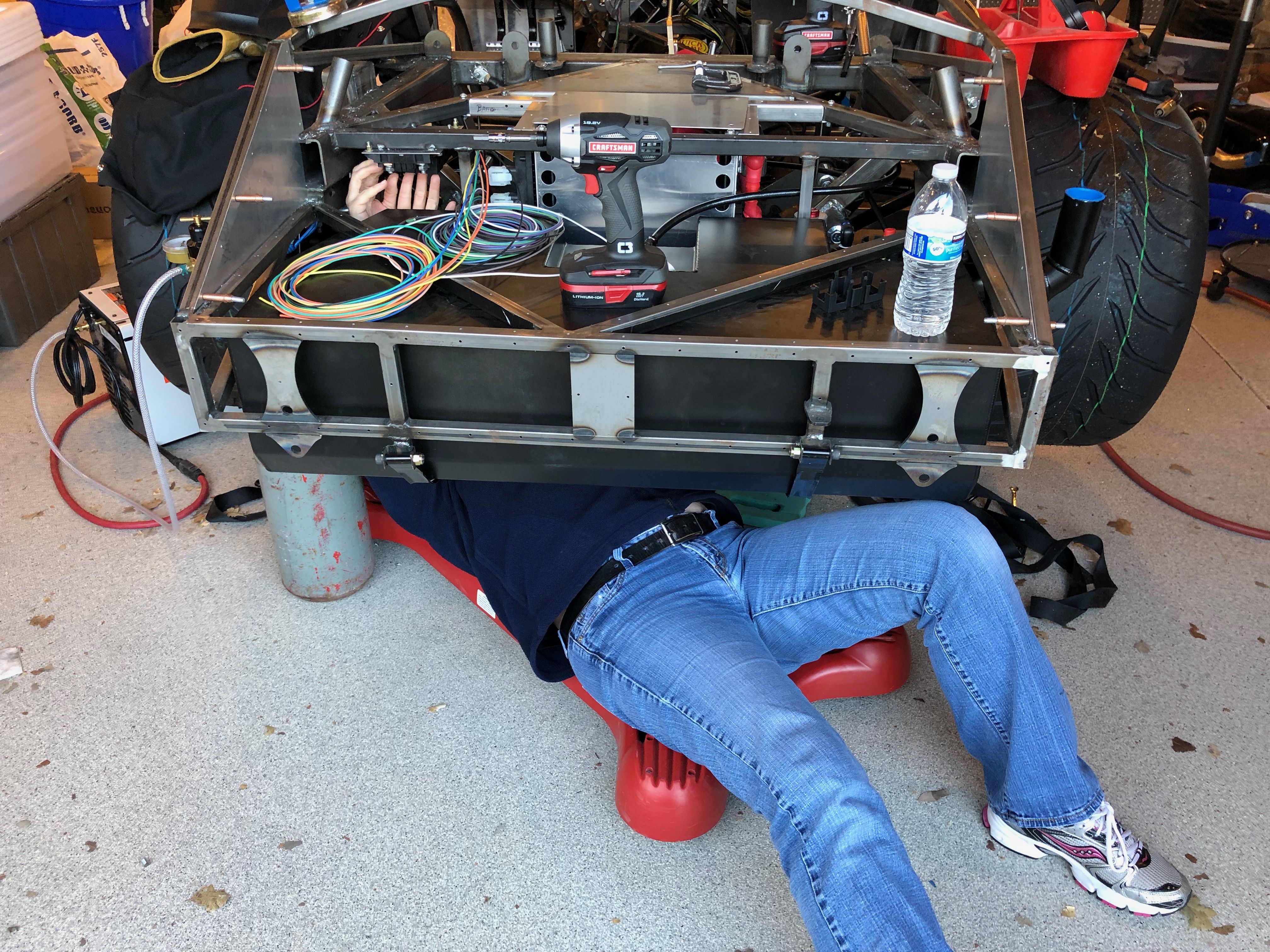
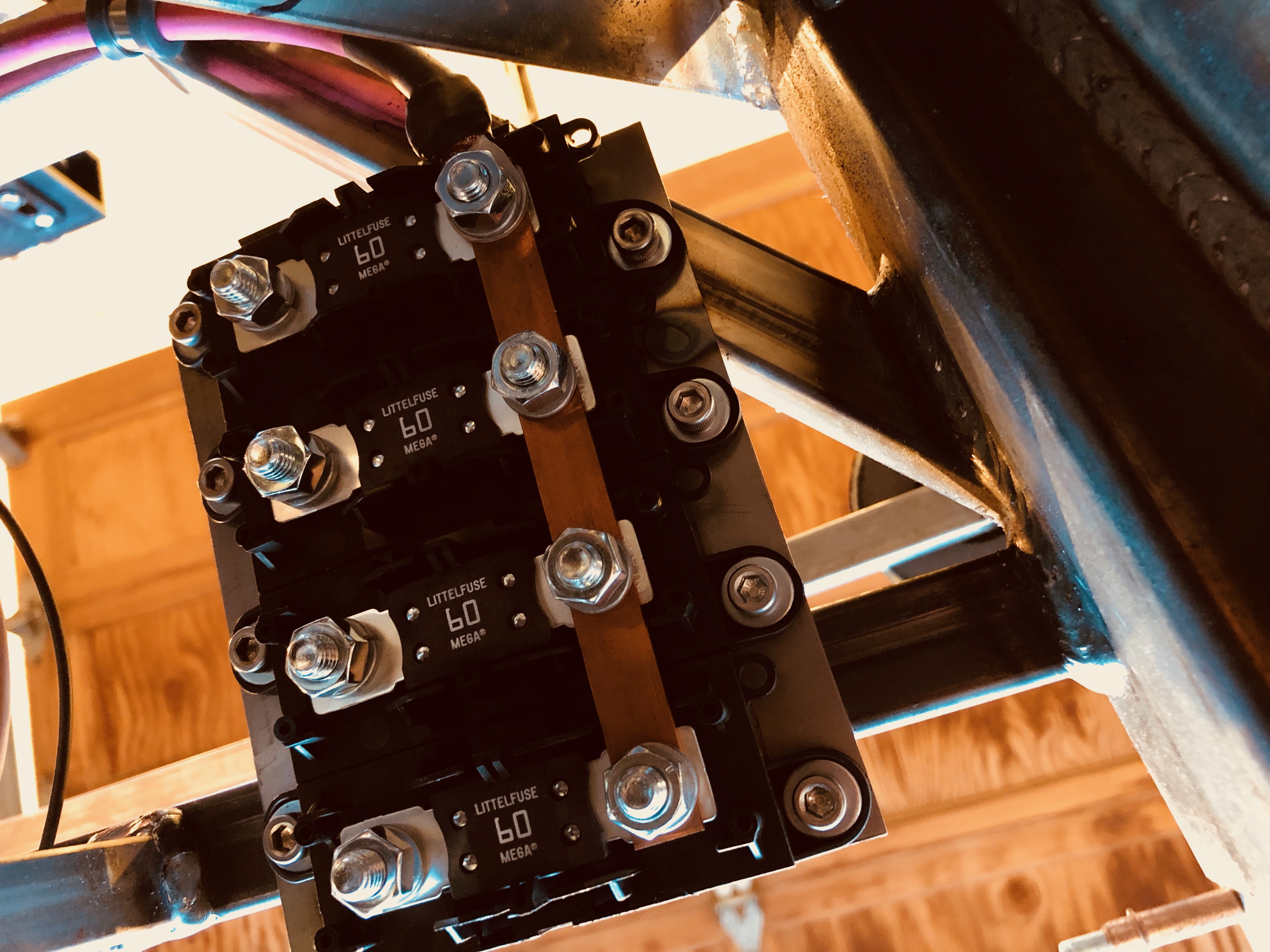
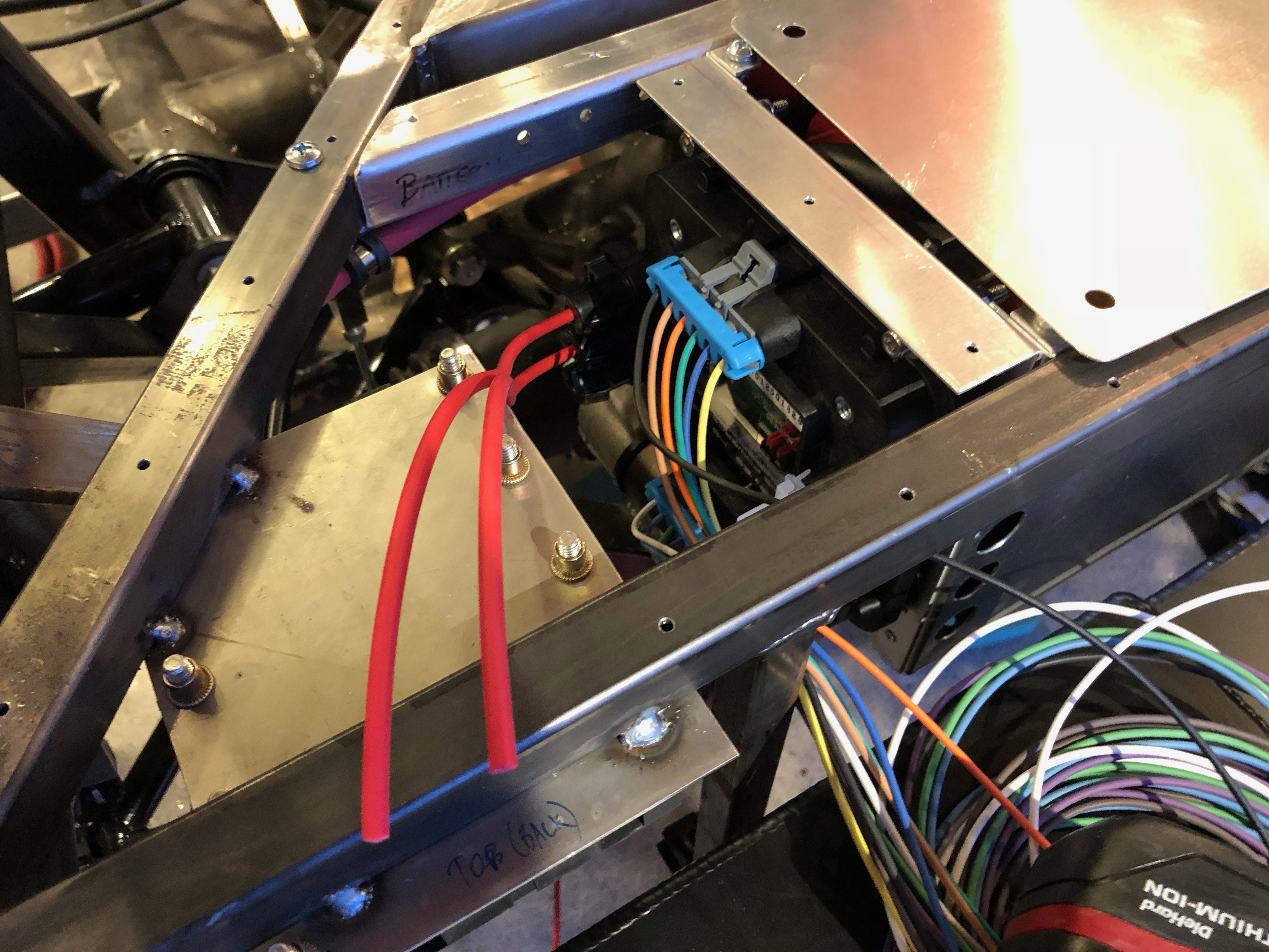
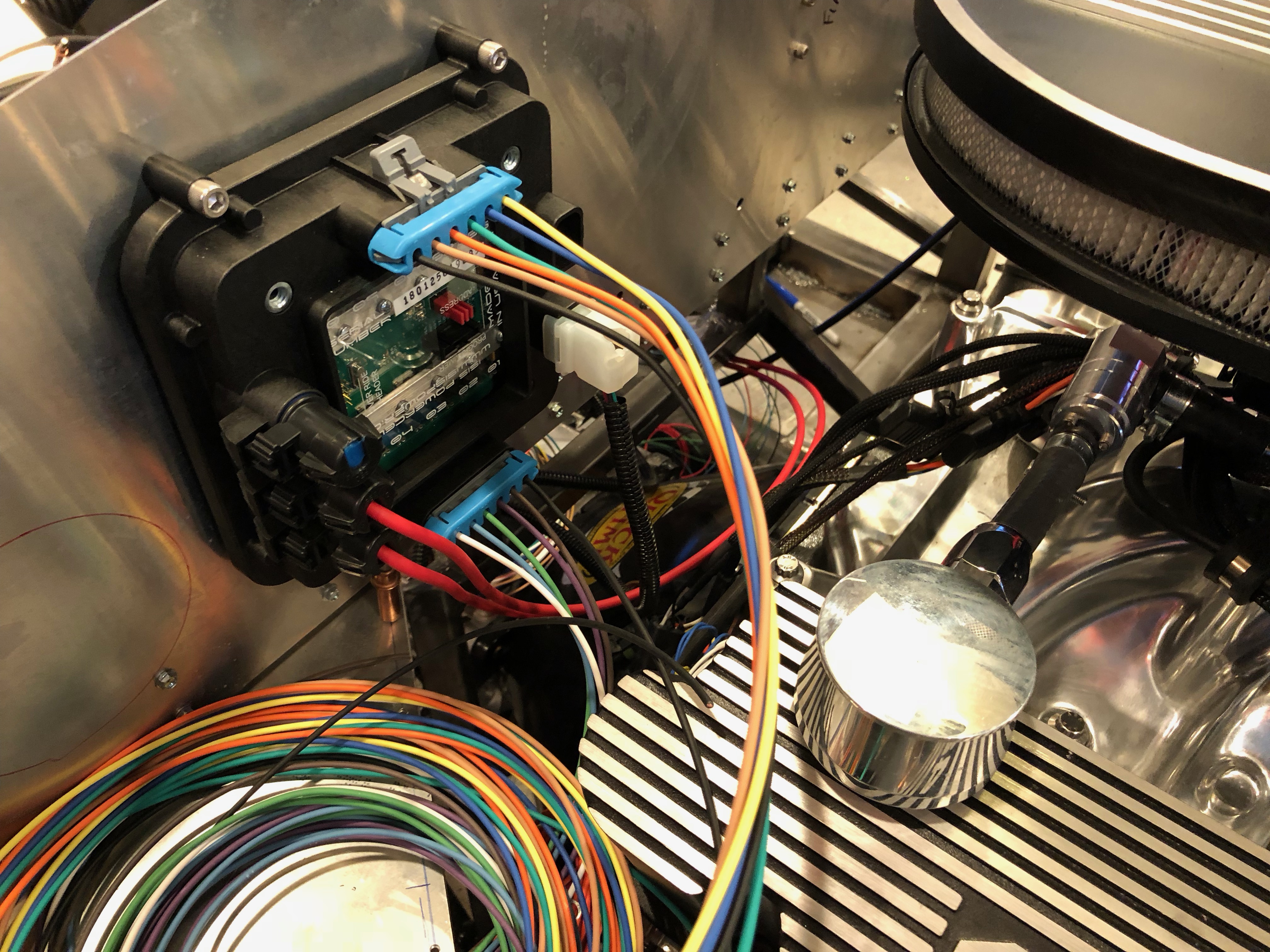
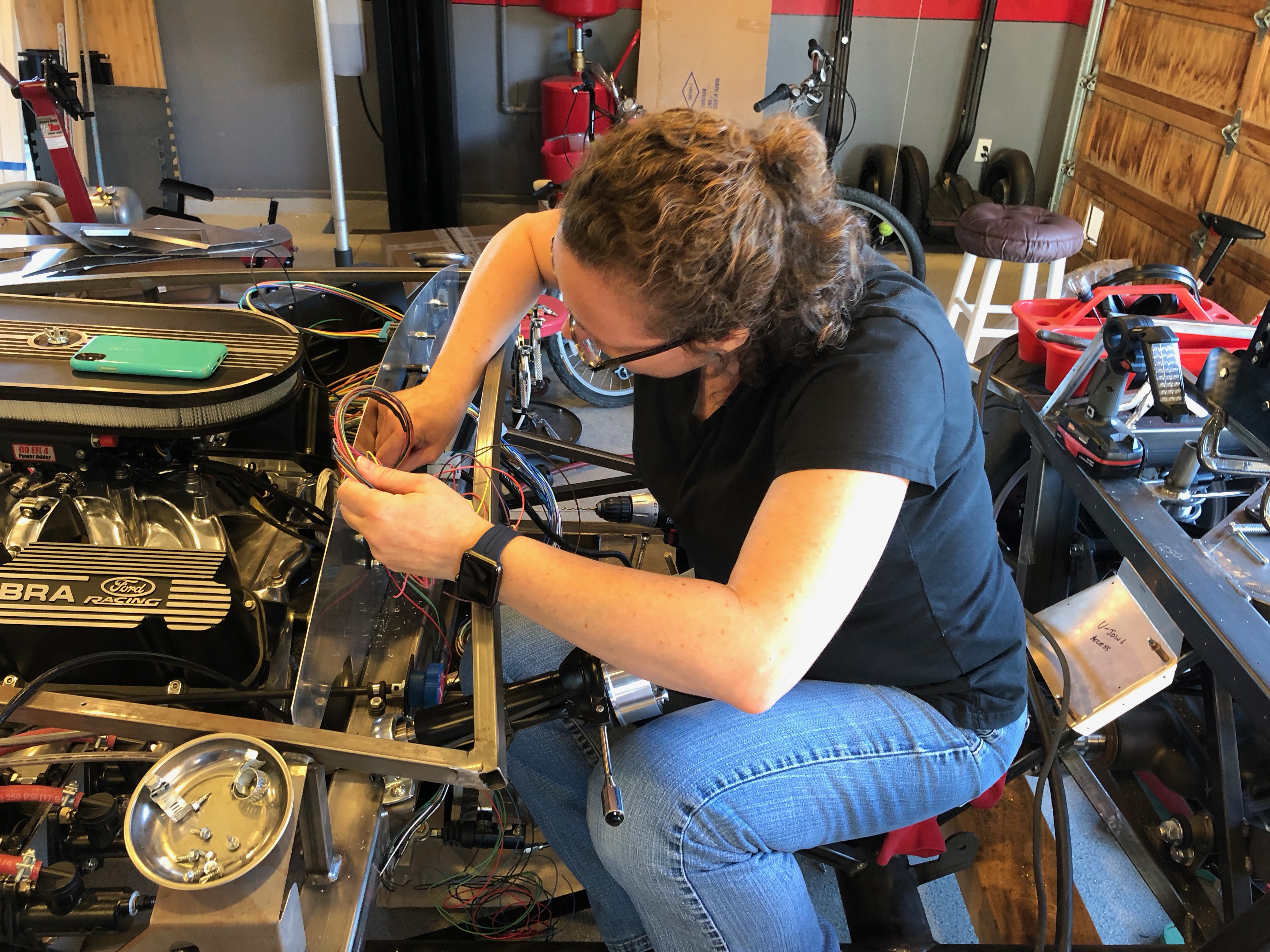
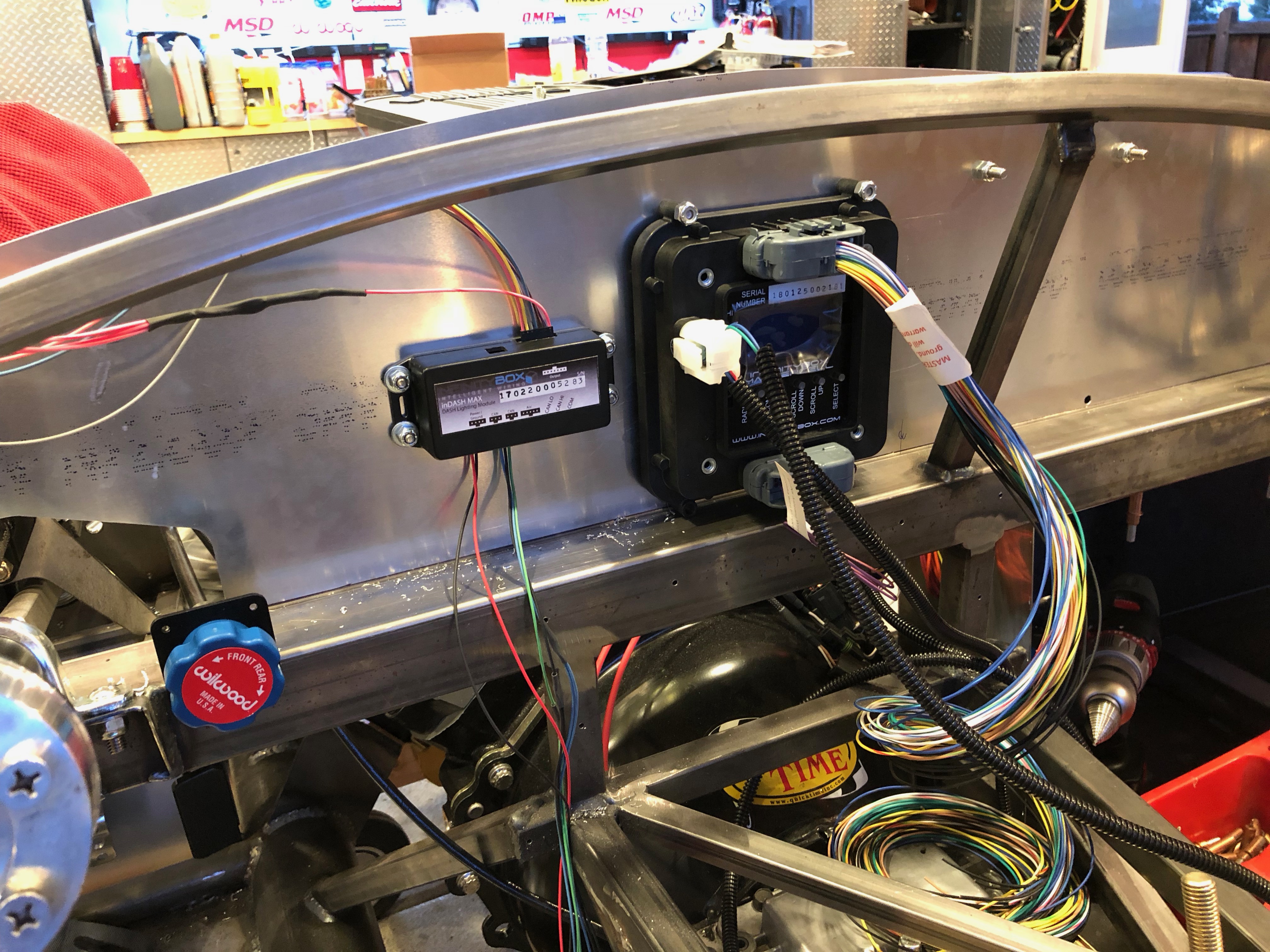
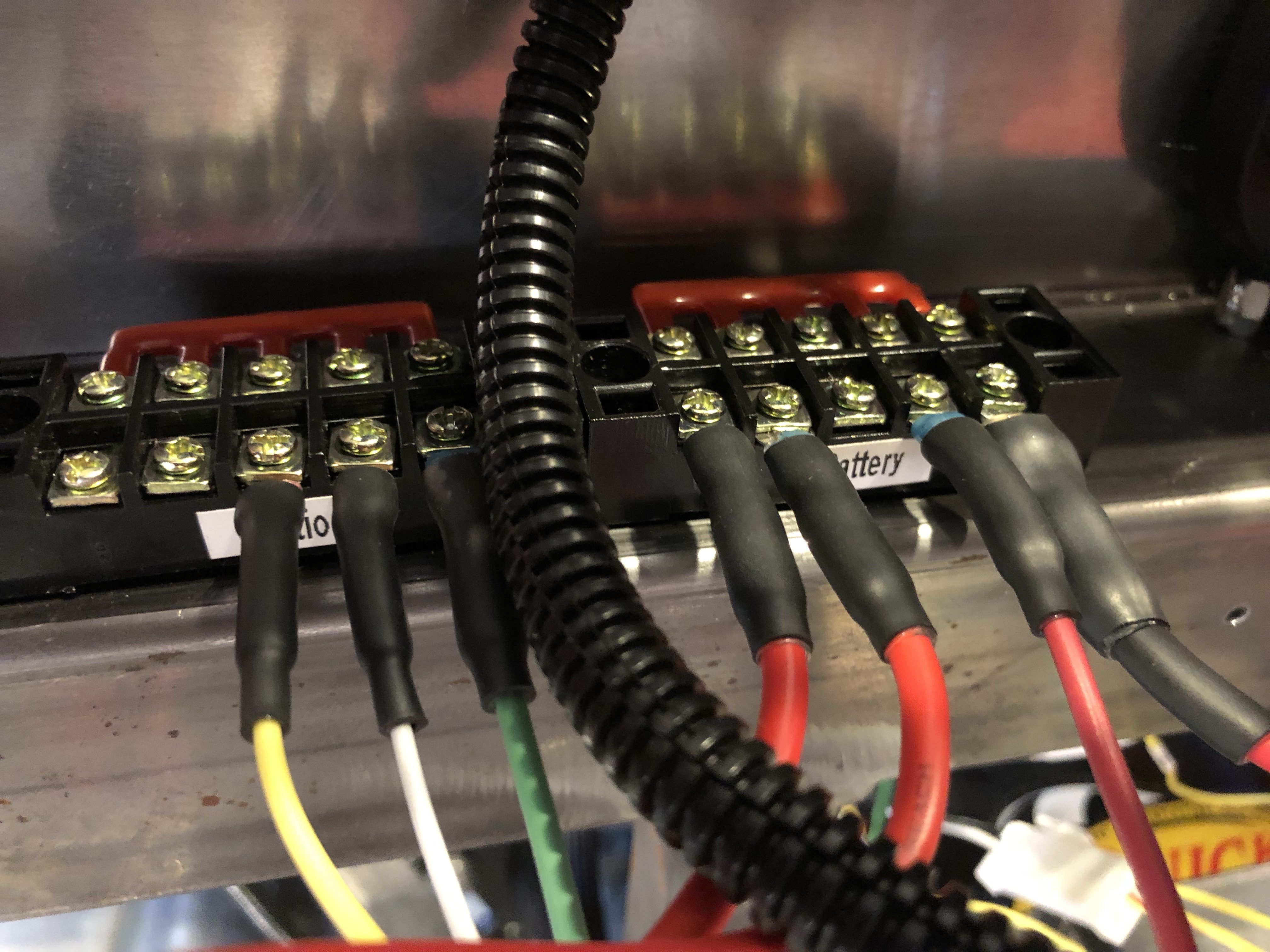
Jenn and I hooked up a number of the circuits connected to the battery and ignition terminal blocks. The rightmost wire in each terminal block is the feed line. The battery terminal block is wired to the starter terminal with a fairly heavy 10AWG wire with inline 30A fuse. The remaining terminals all have smaller inline fuses protecting the wires connecting them to each battery load.

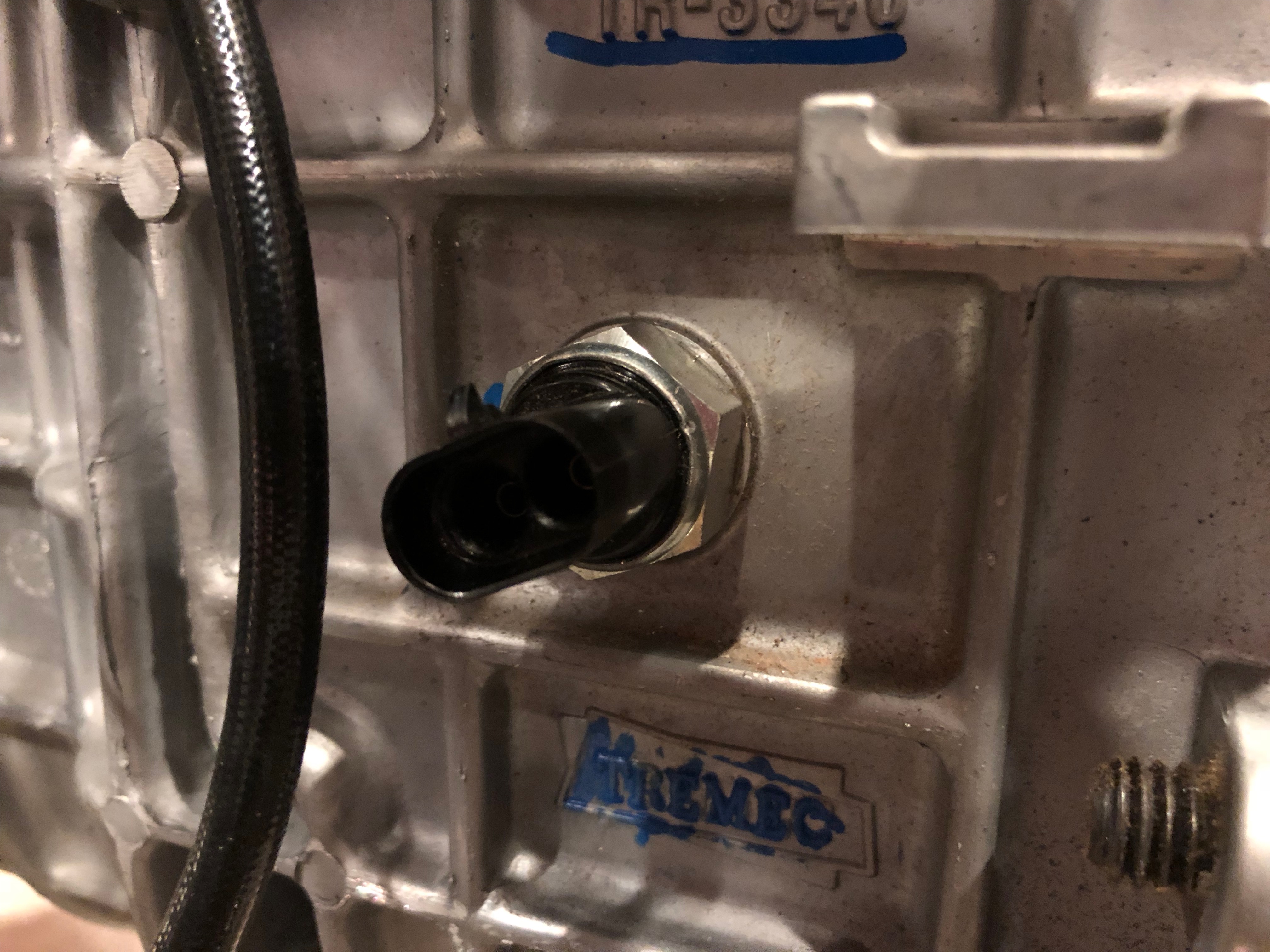
The ignition terminal block is wired to the ignition output on the front load cell. There are still a couple of additional wires to connect to these terminal blocks, but this is enough to get the gauges working and engine running.

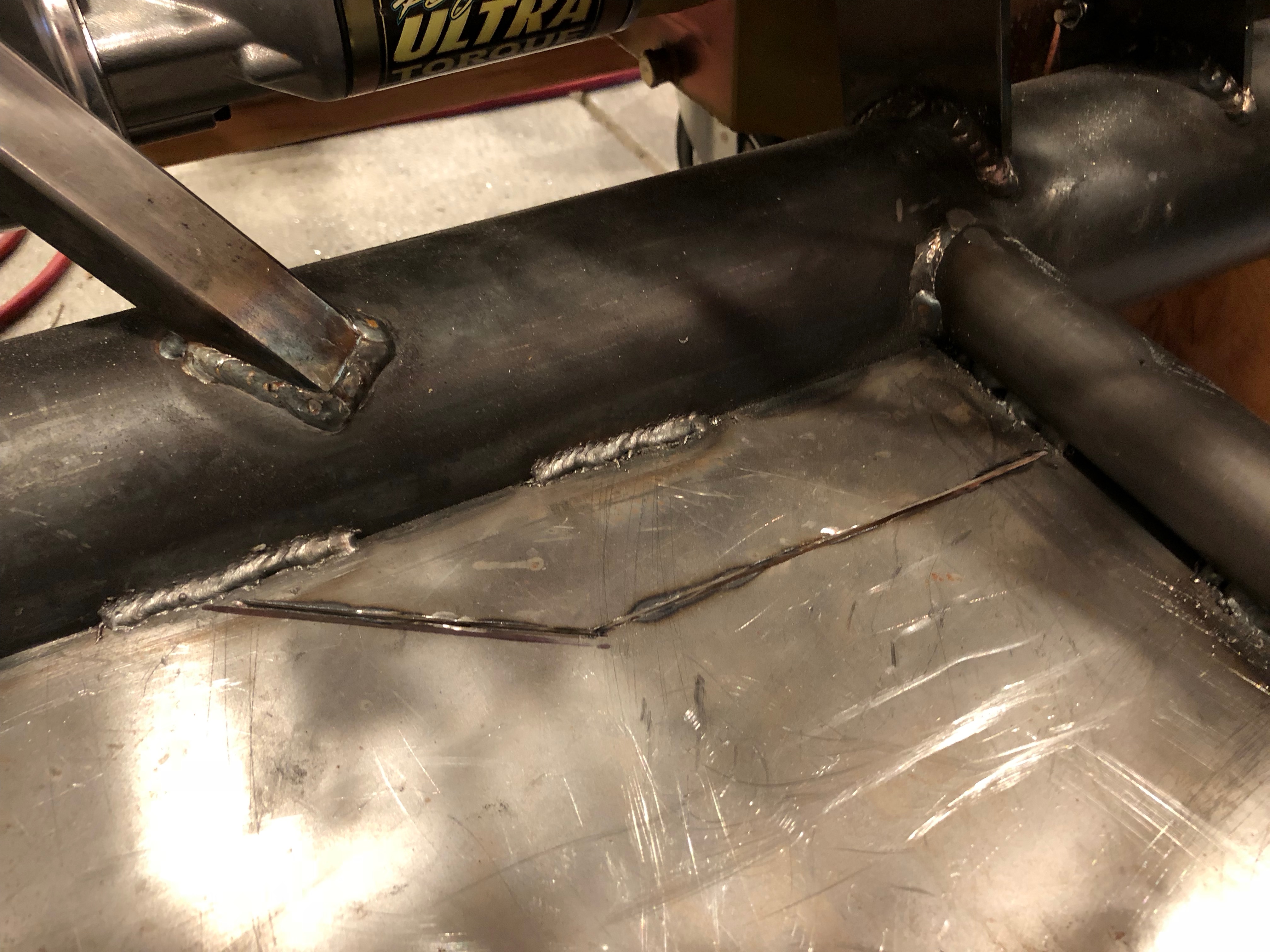
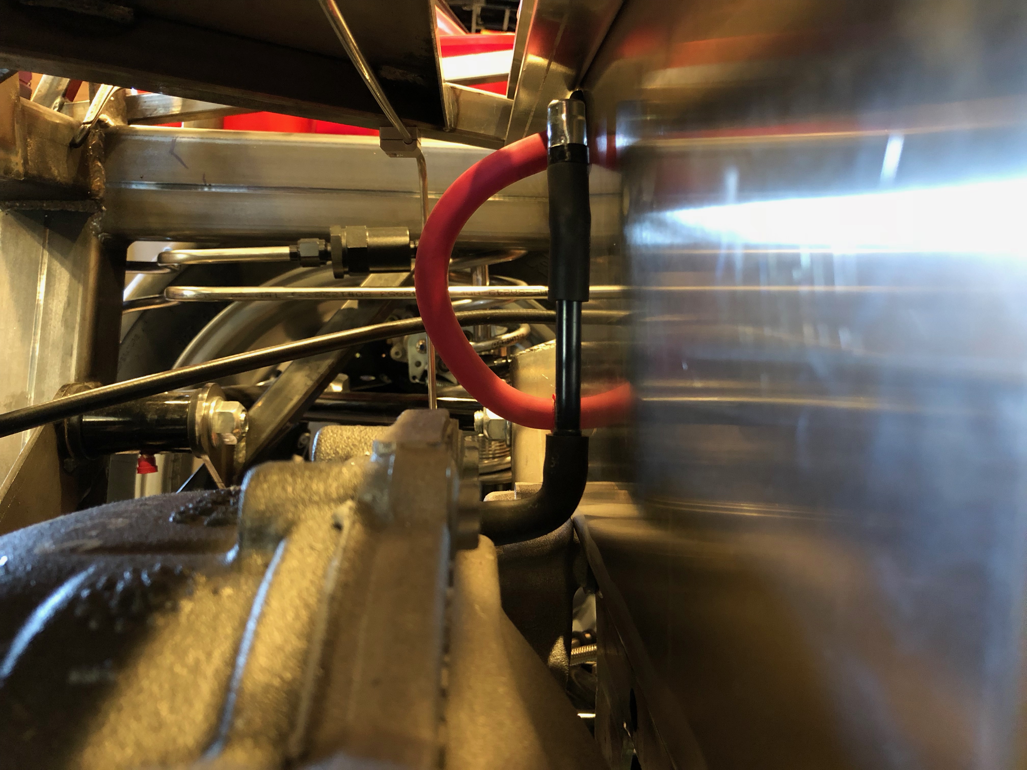
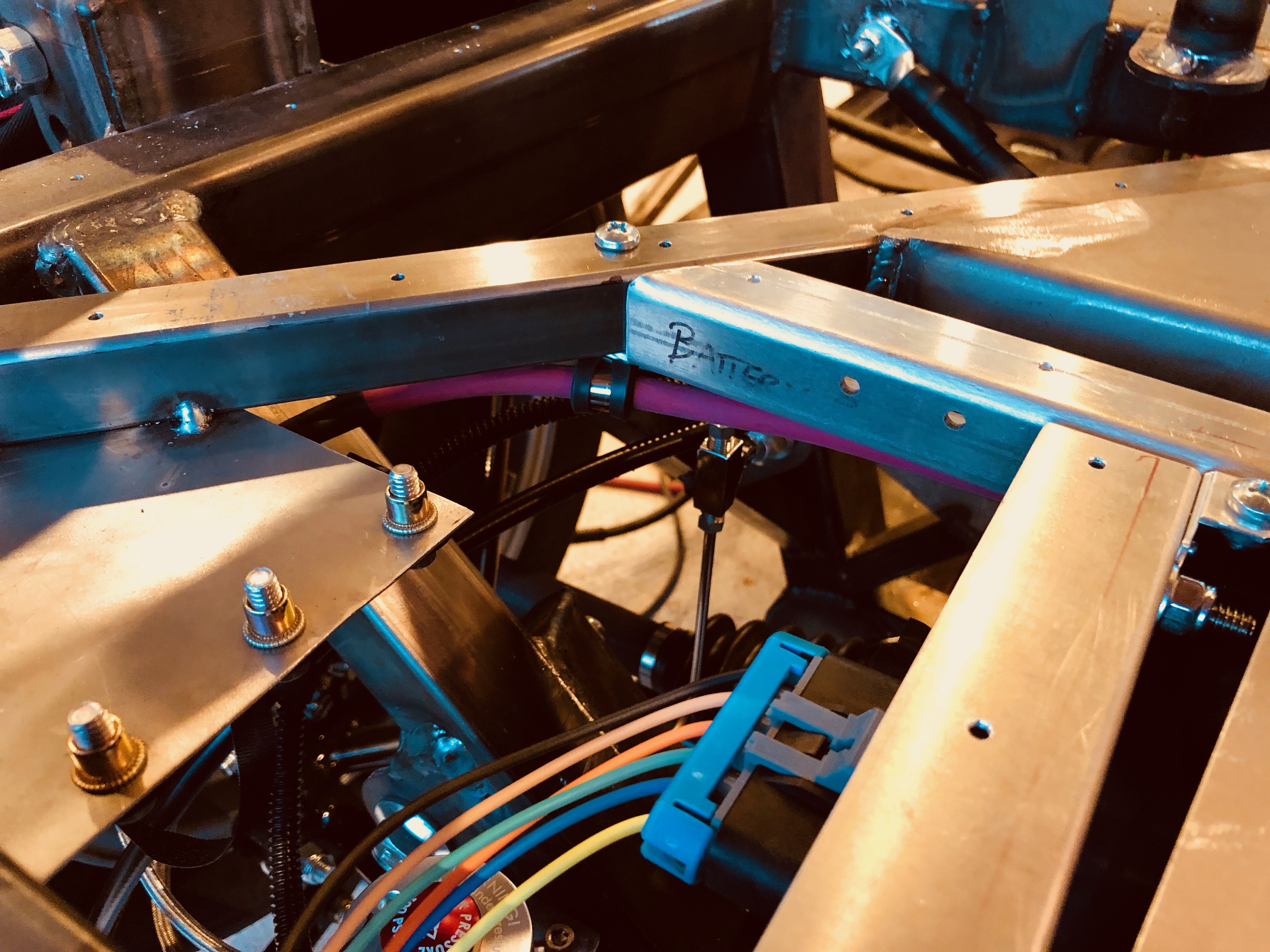
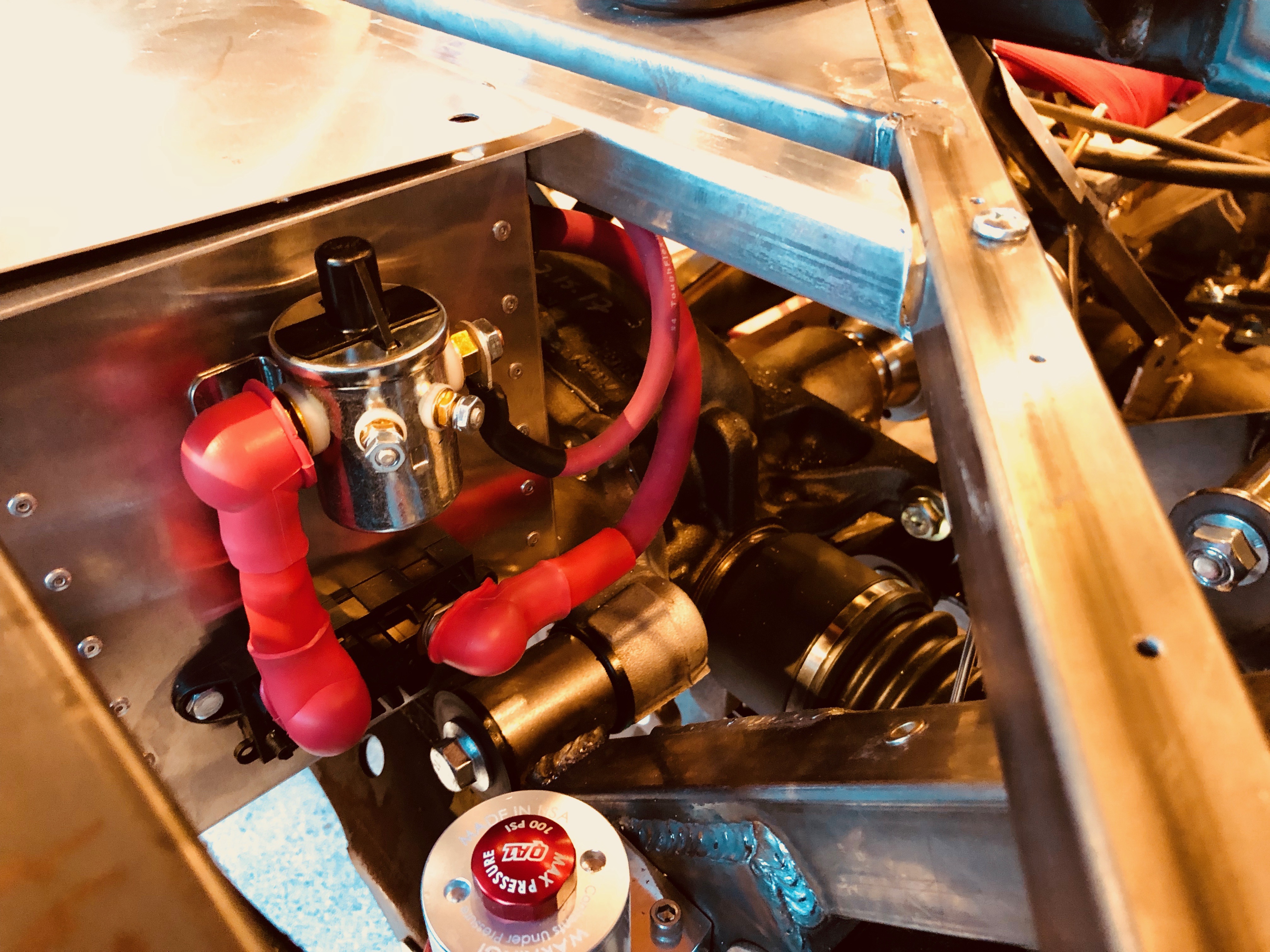
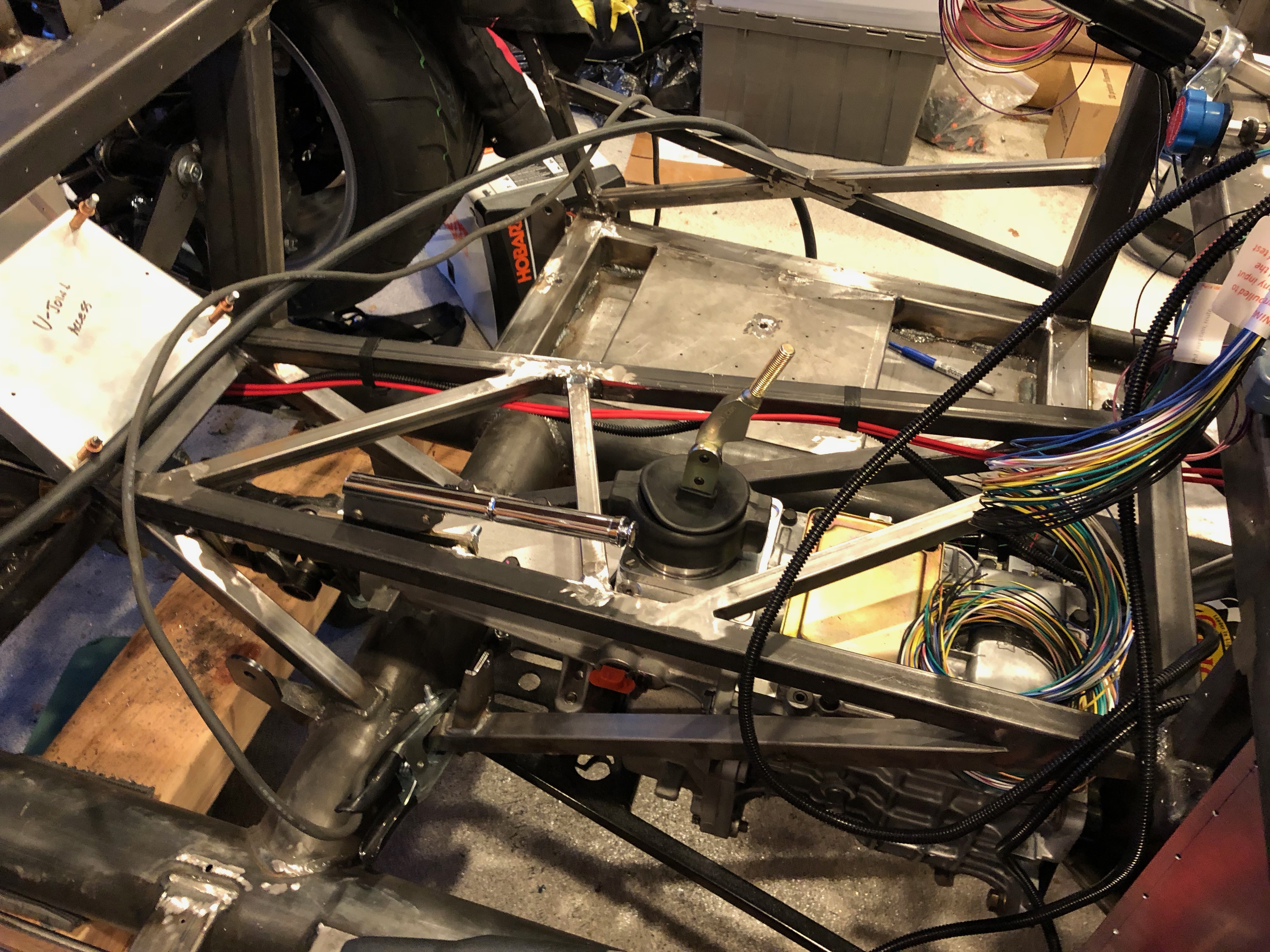
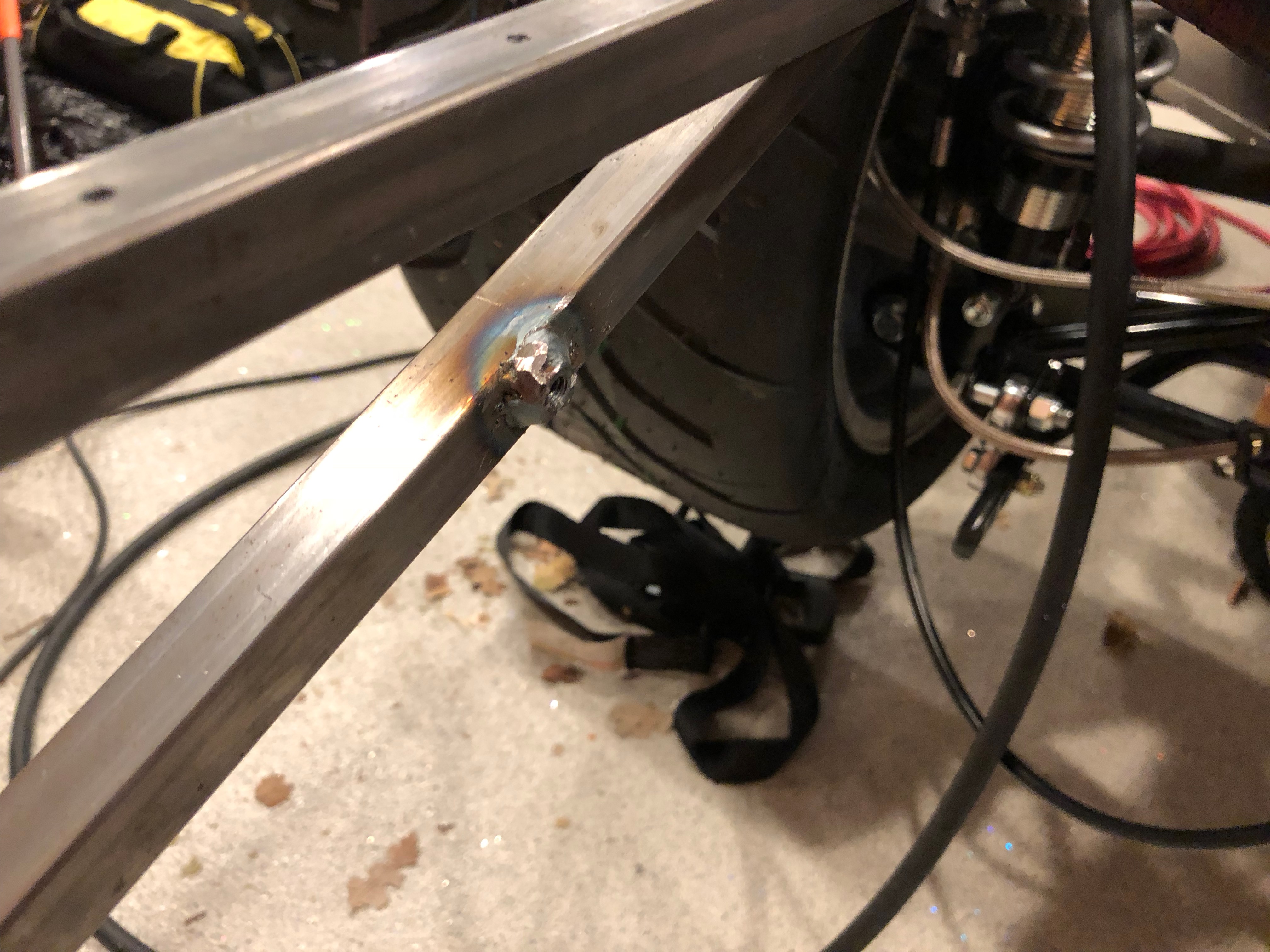
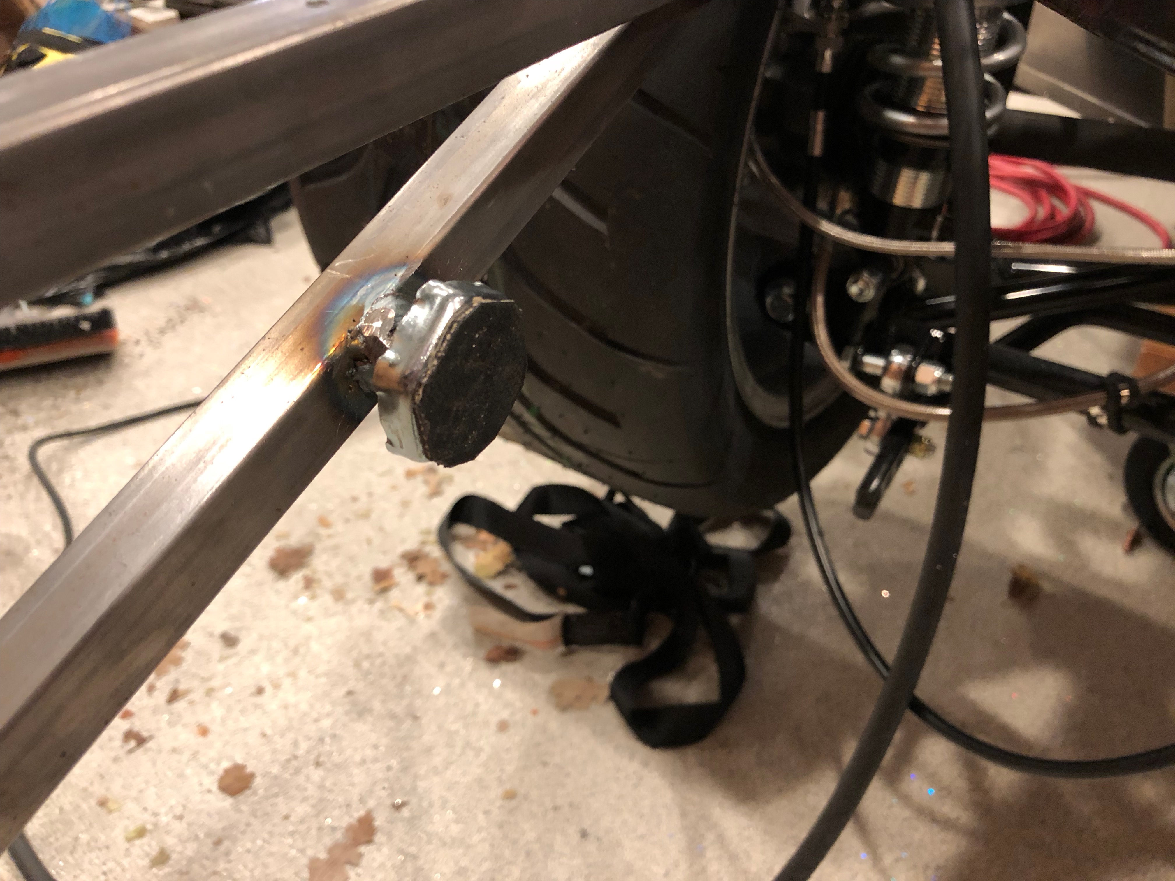
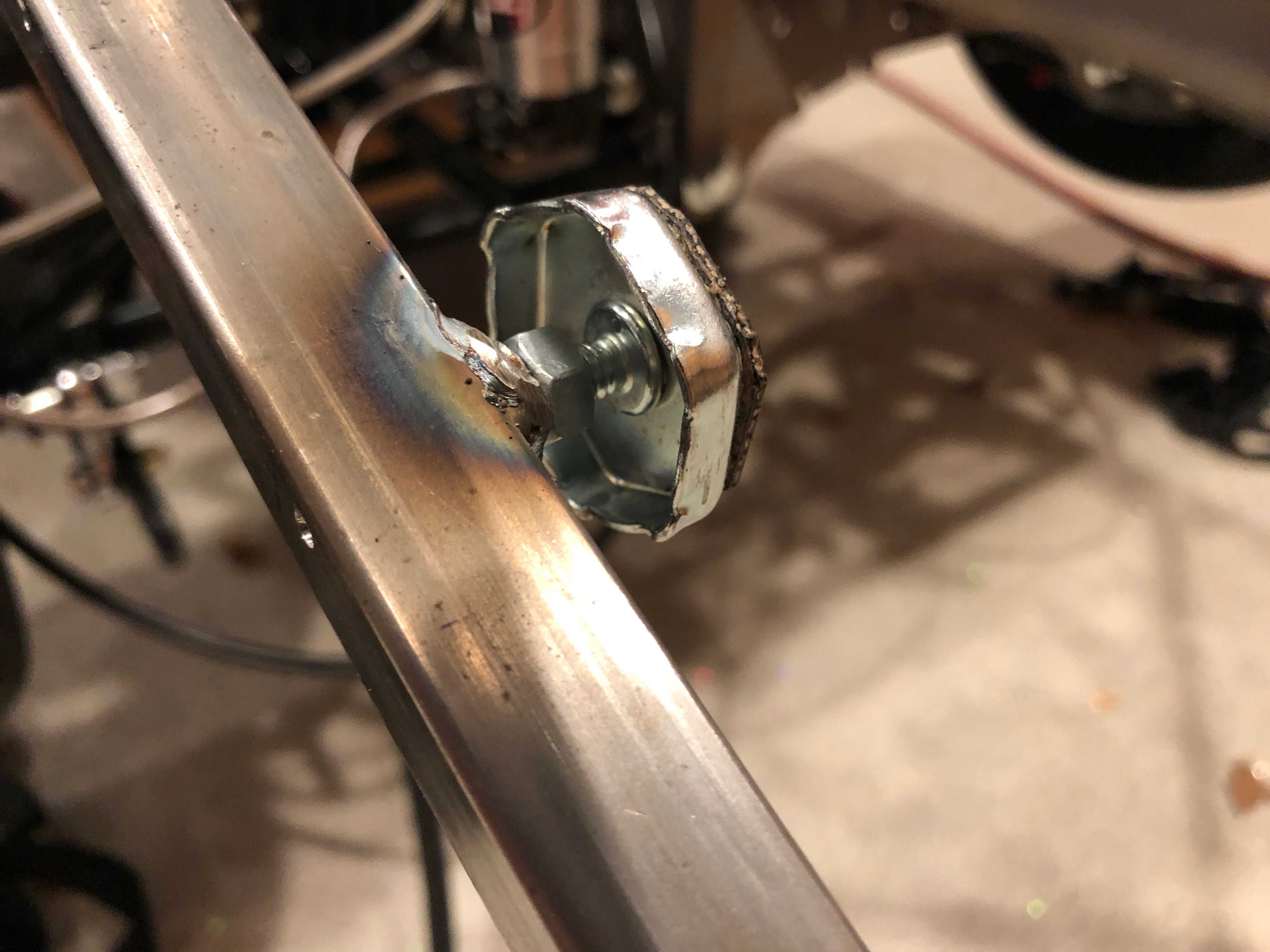
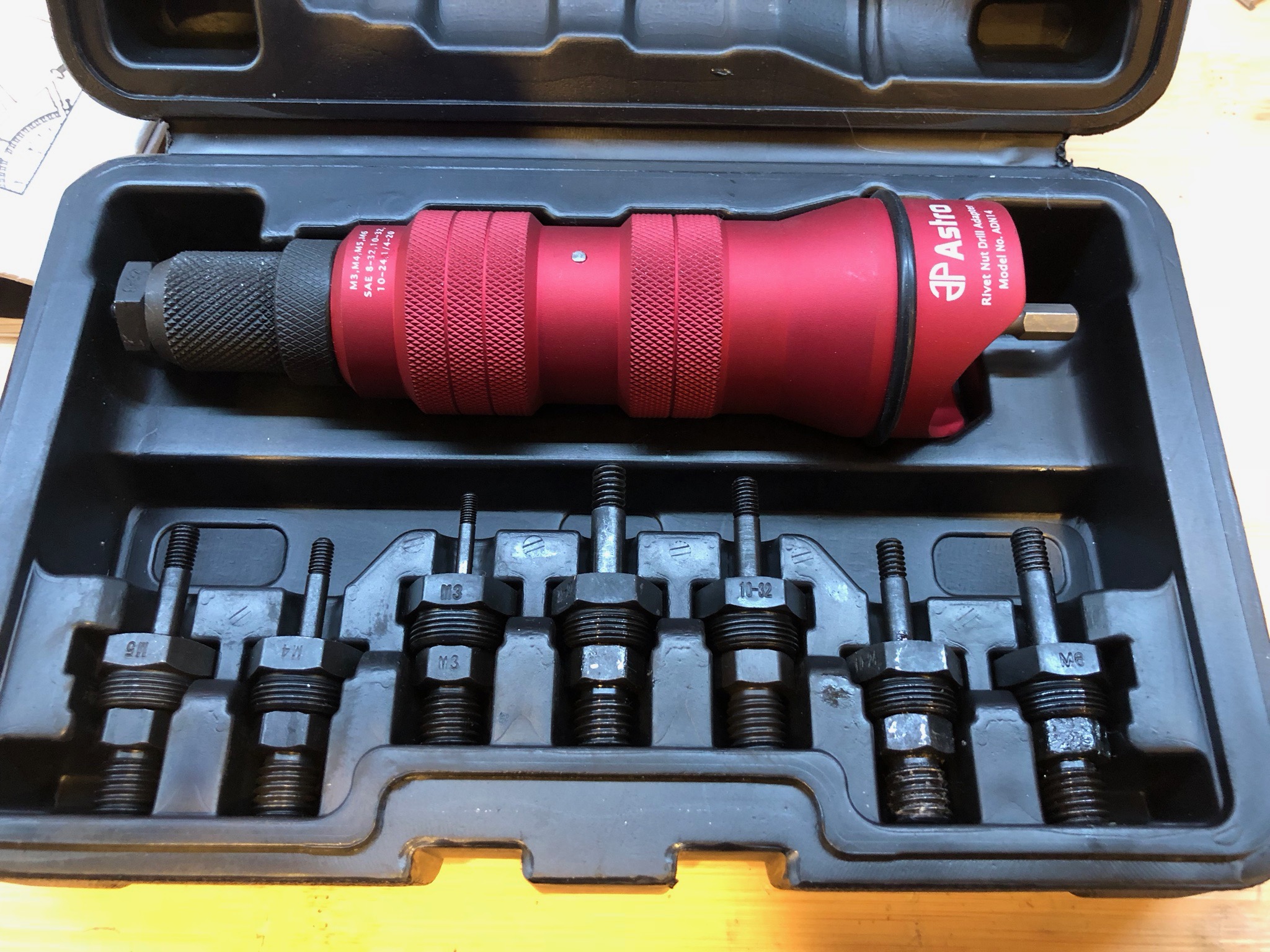
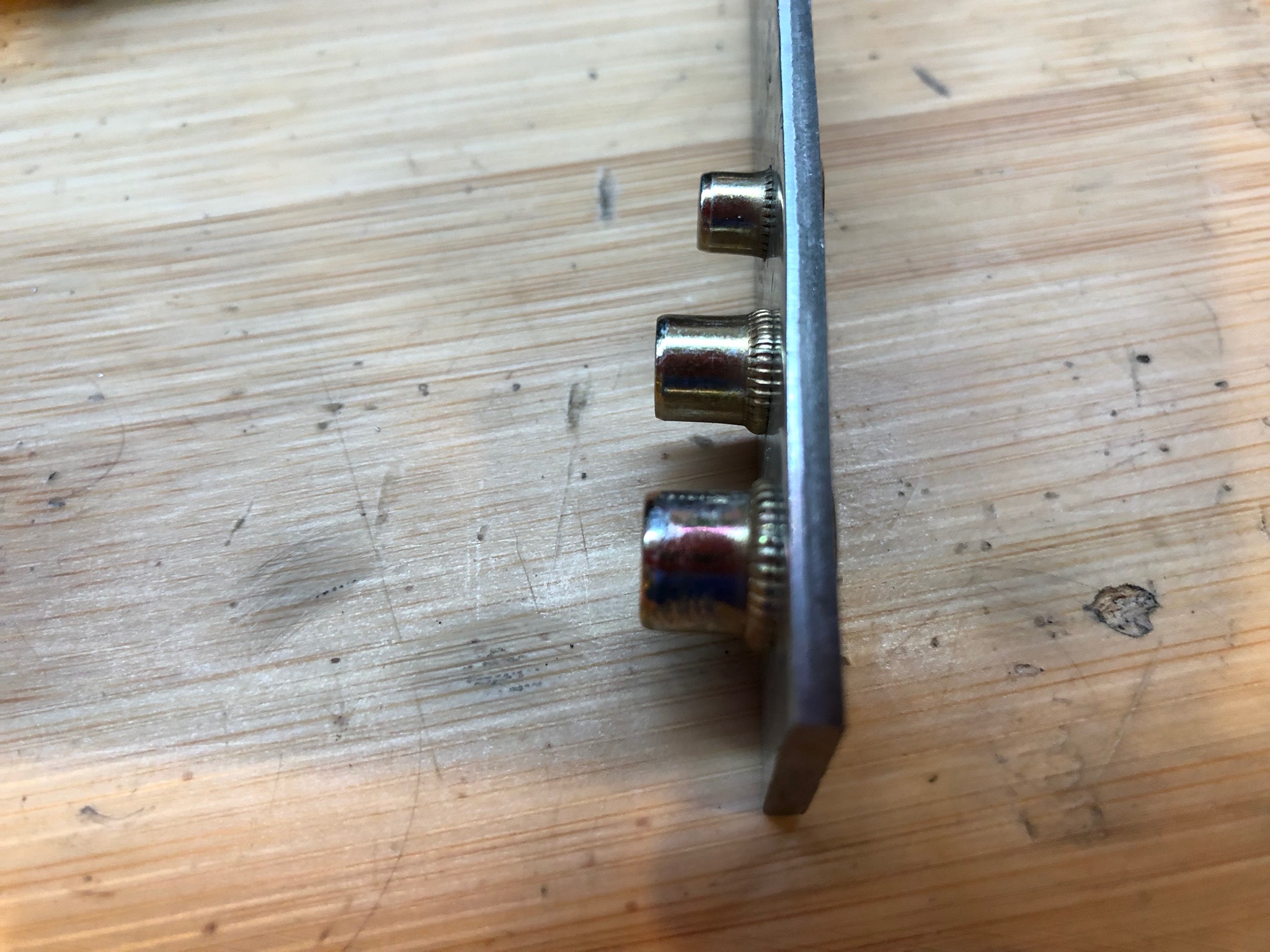
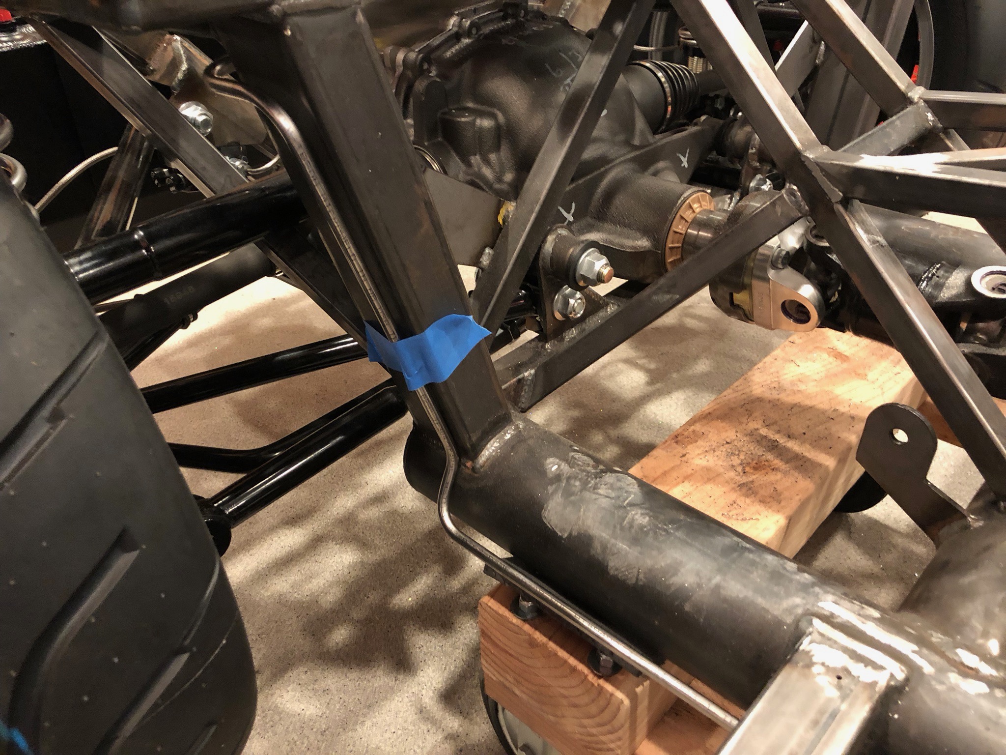
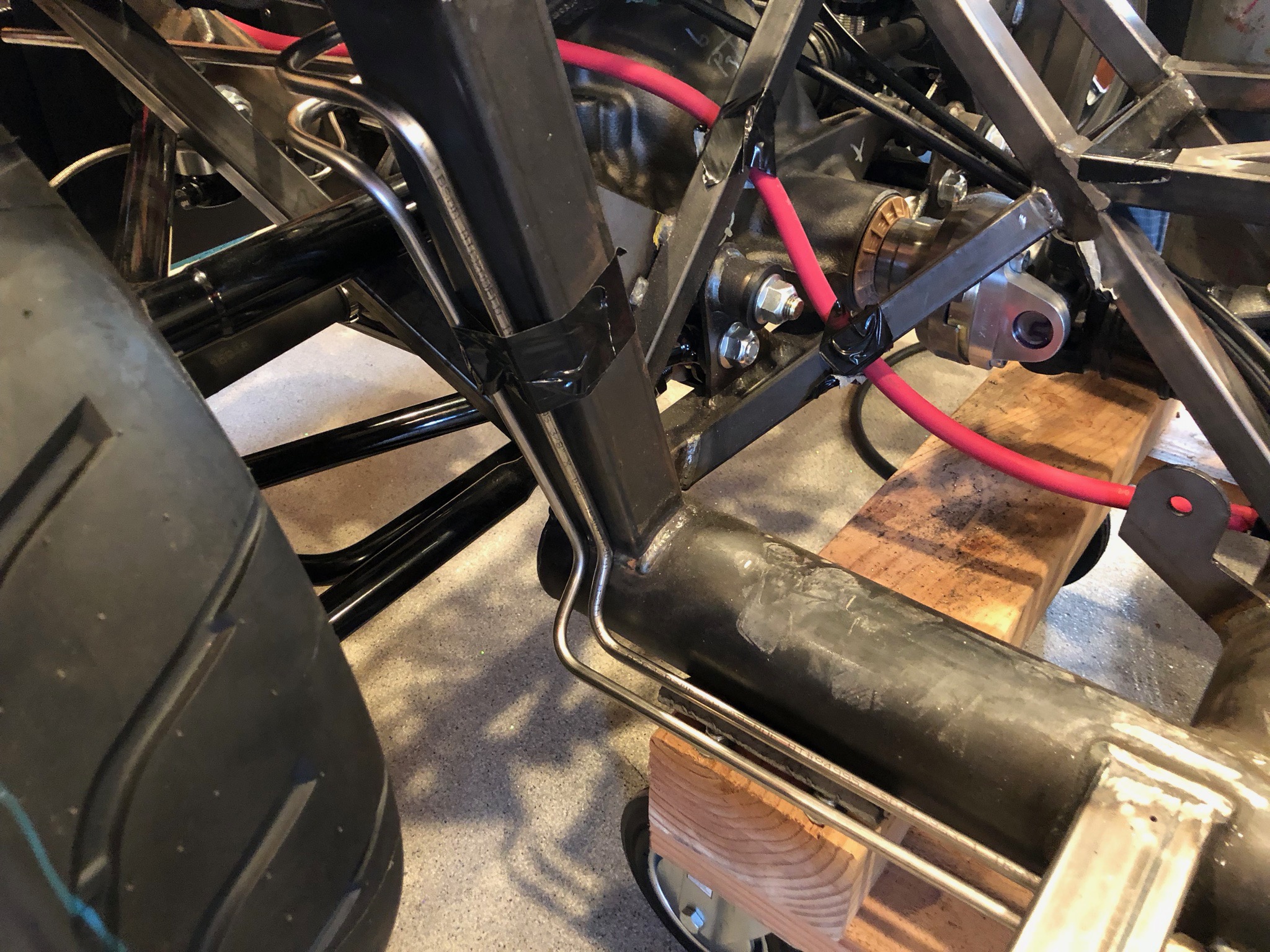
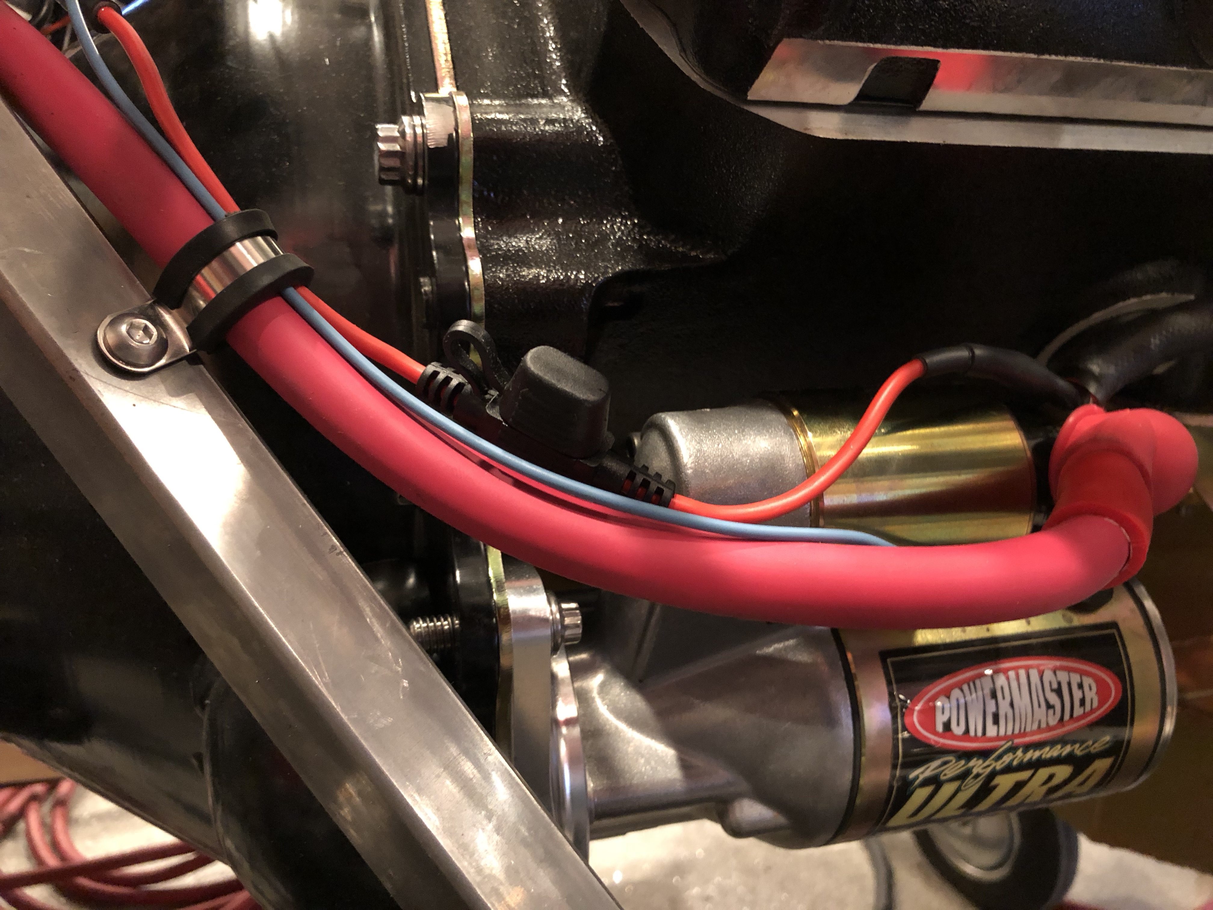
Jenn and I wrapped up the starter wiring with the 30A inline fuse. Normally, the battery feed would be connected directly to the battery to minimize voltage drop during engine cranking, but that is minimal with a 2/0 wire to the starter. I also installed a rivnut to secure the wires to the chassis near the bellhousing.

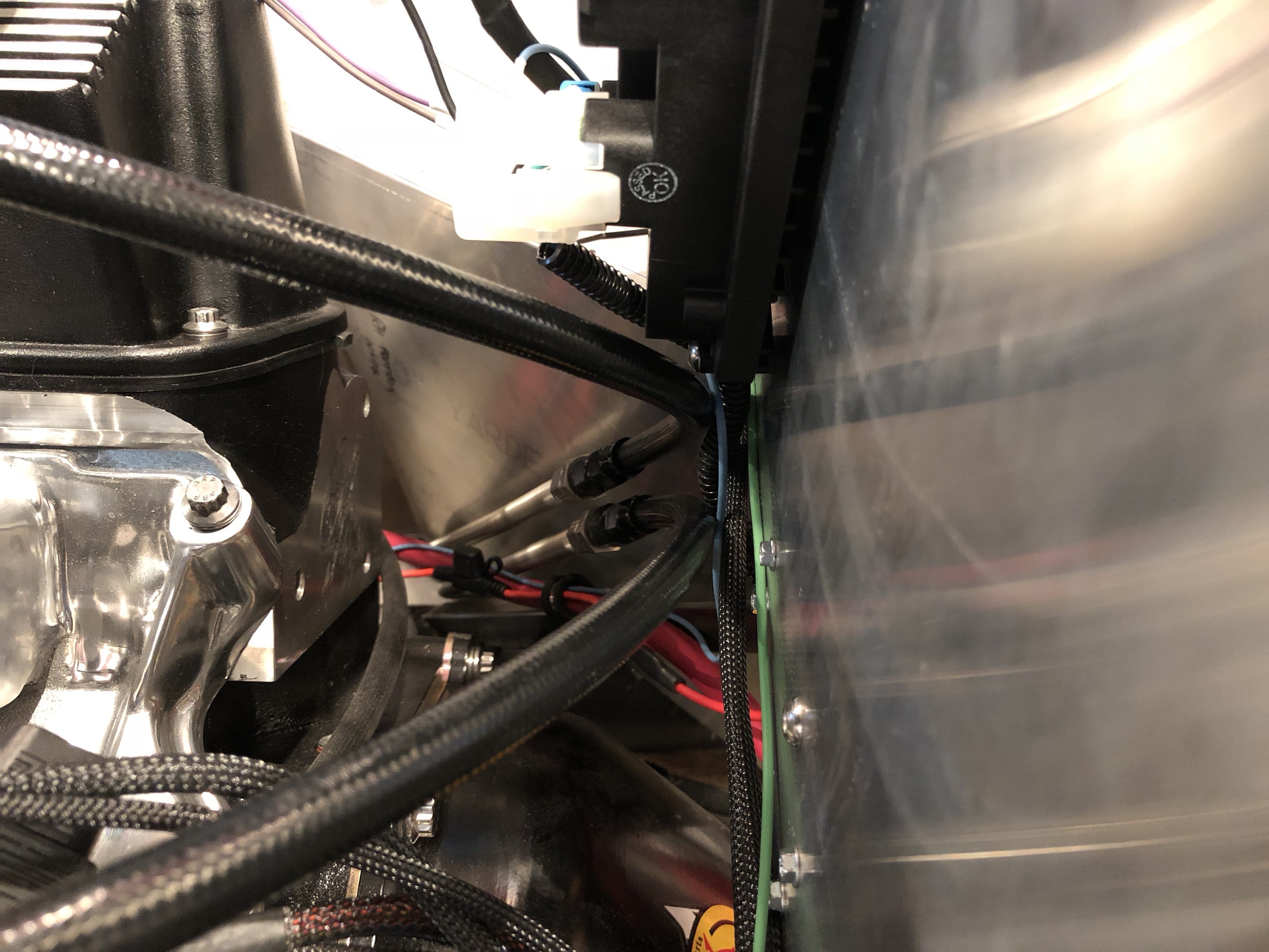
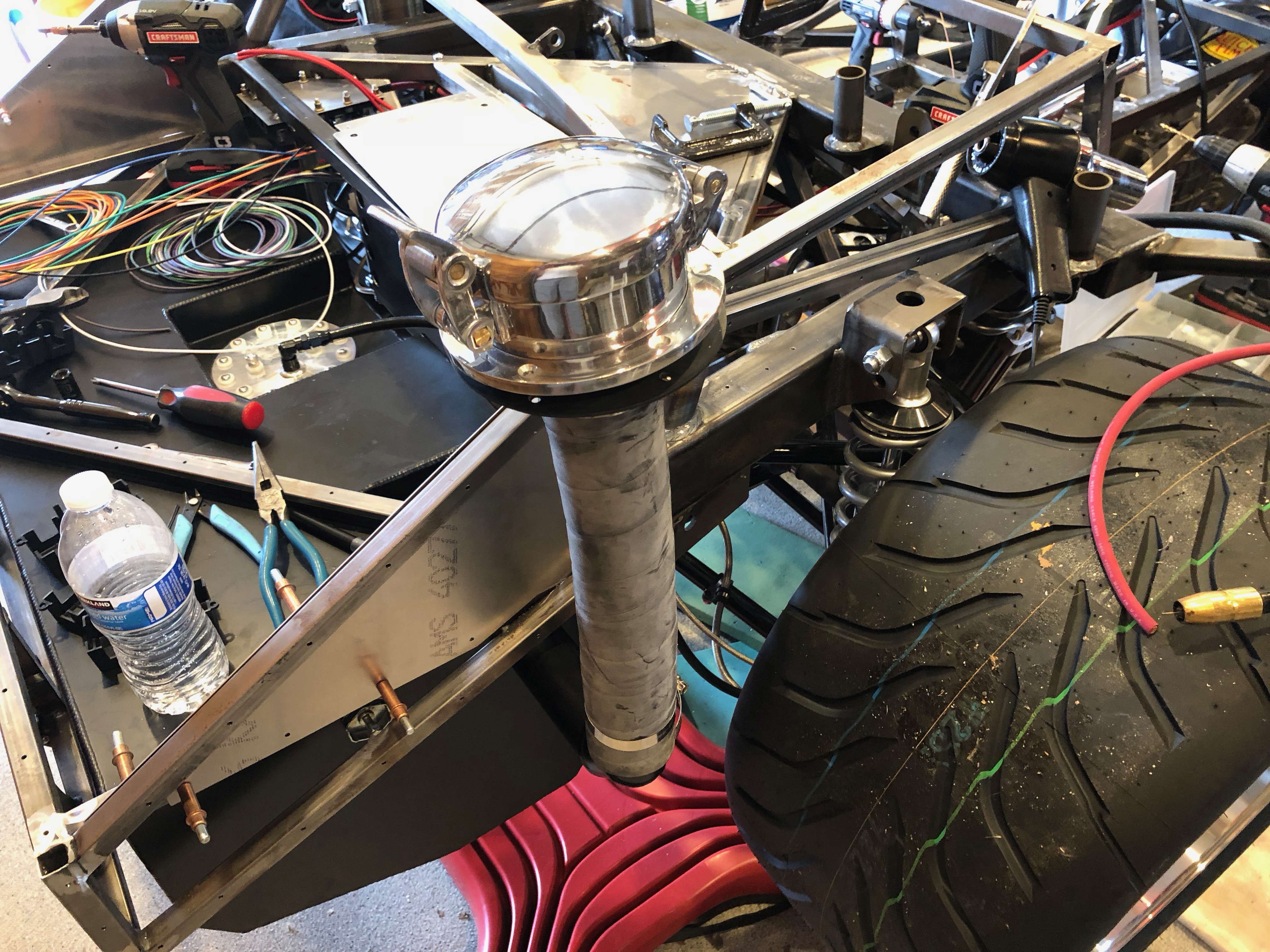
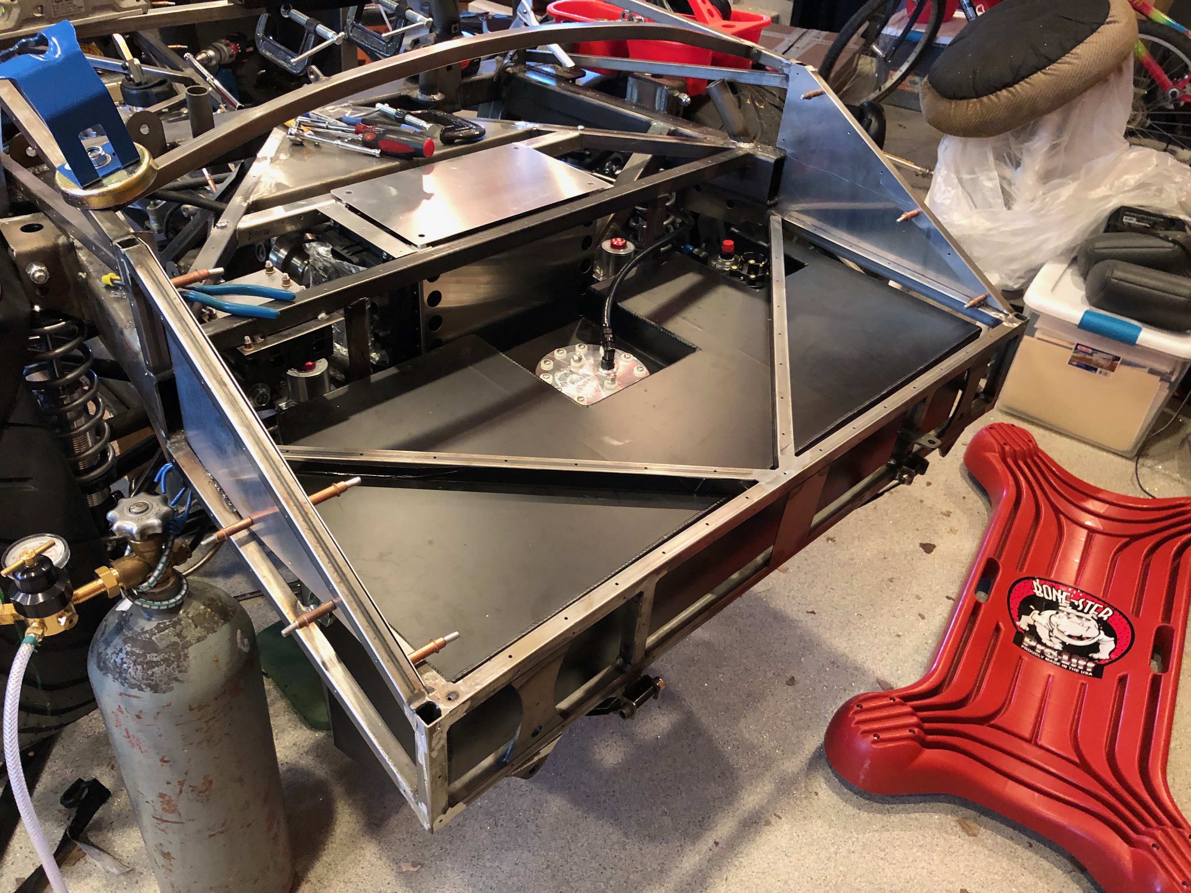
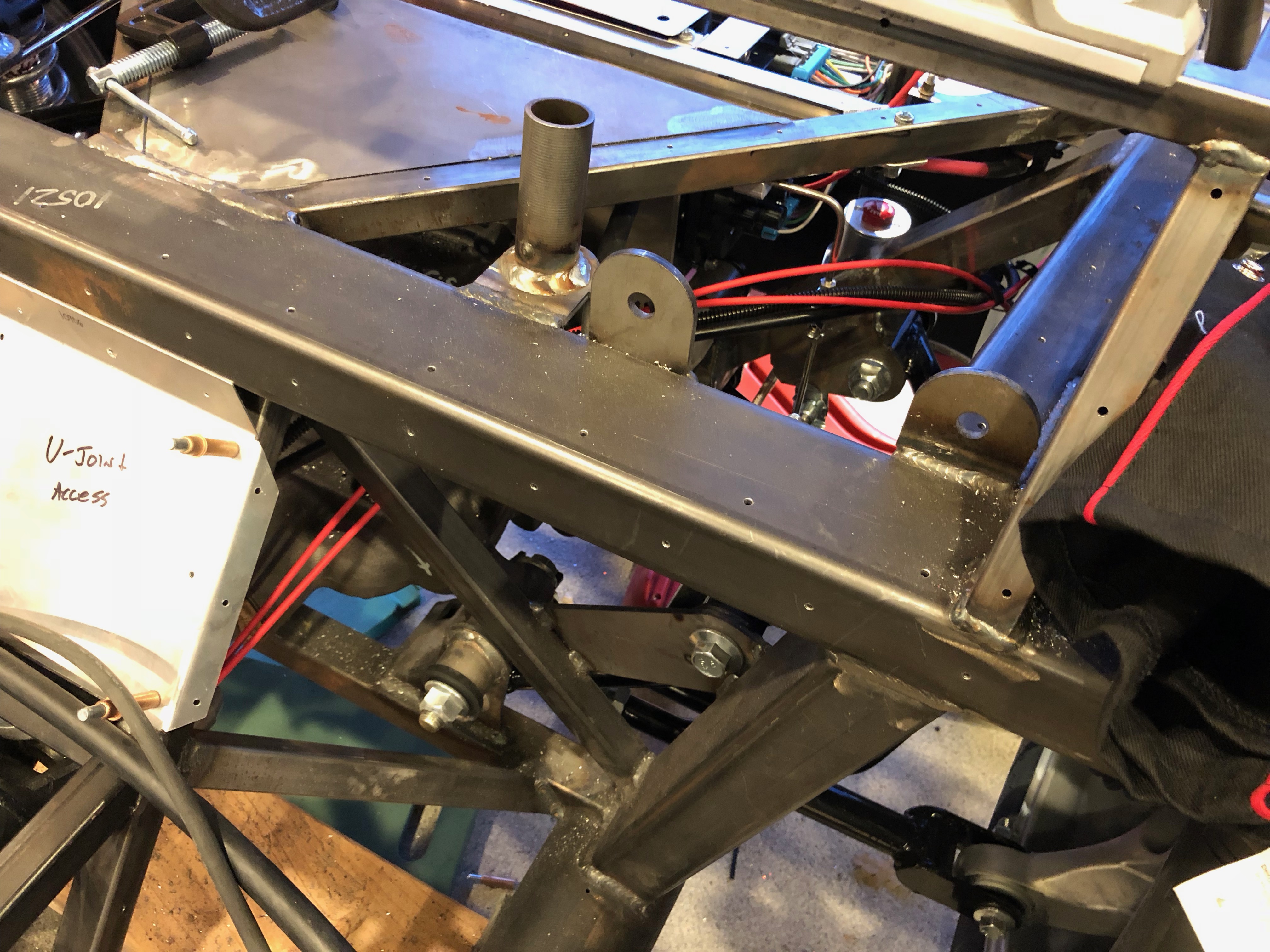
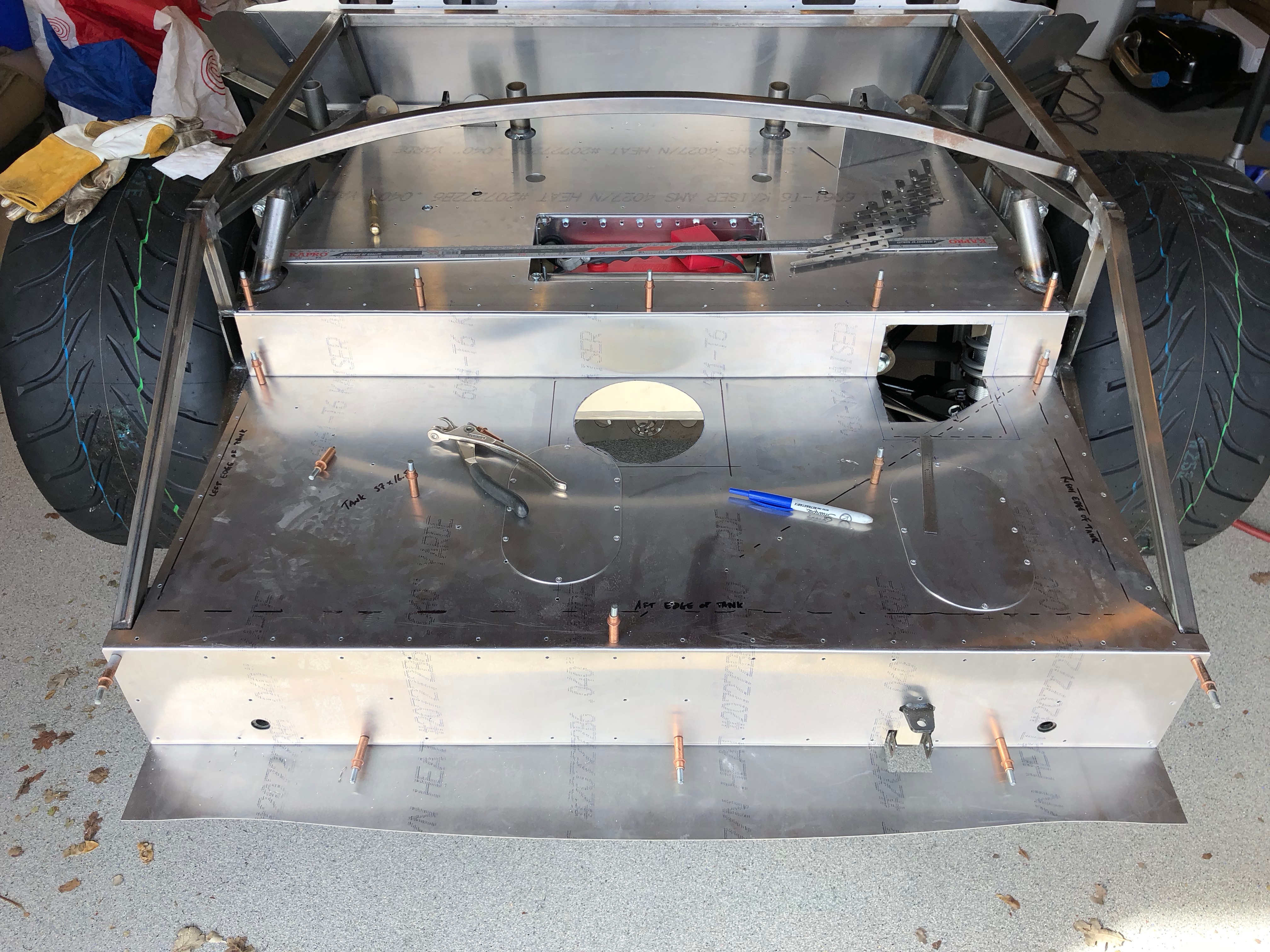
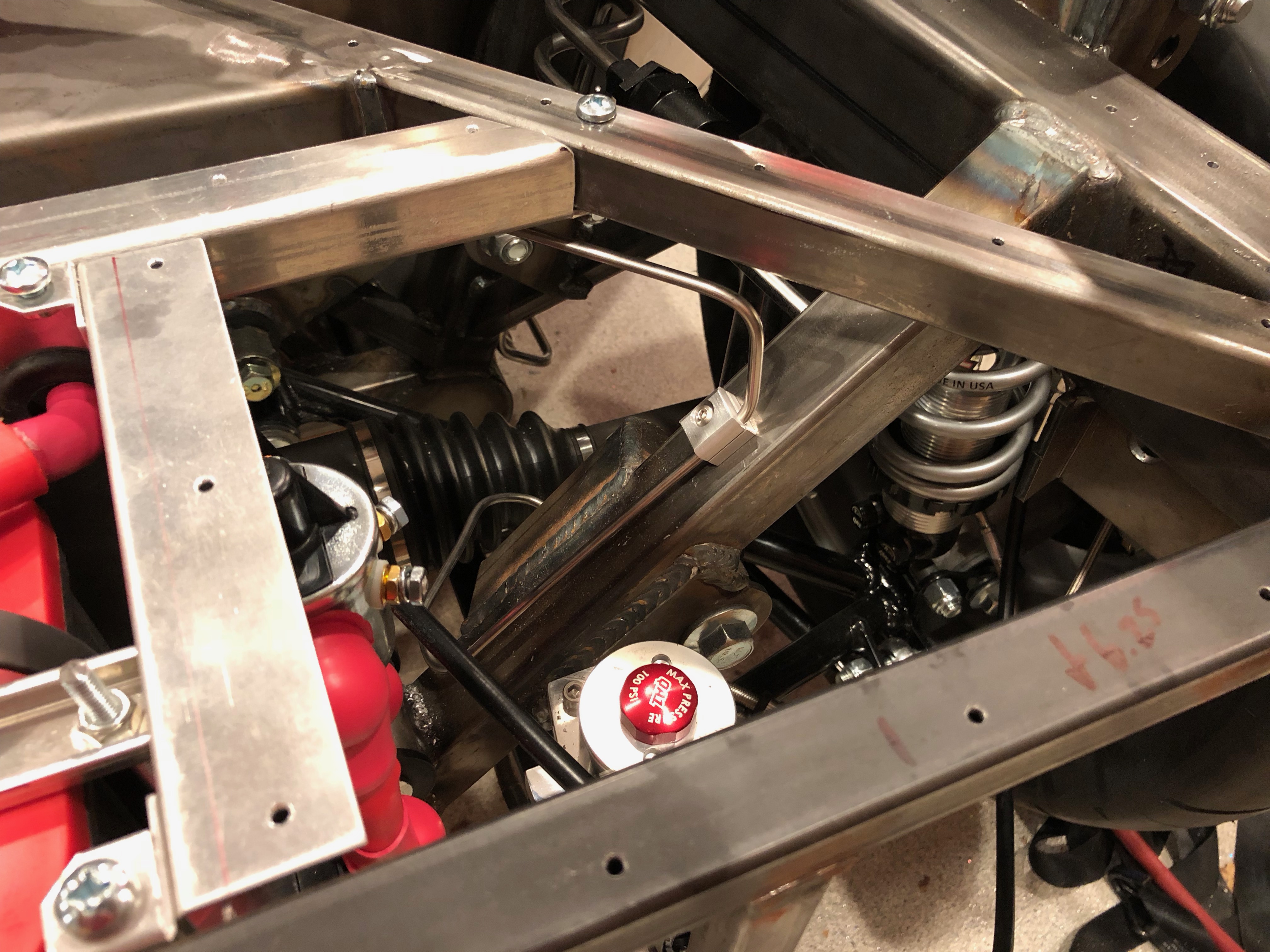
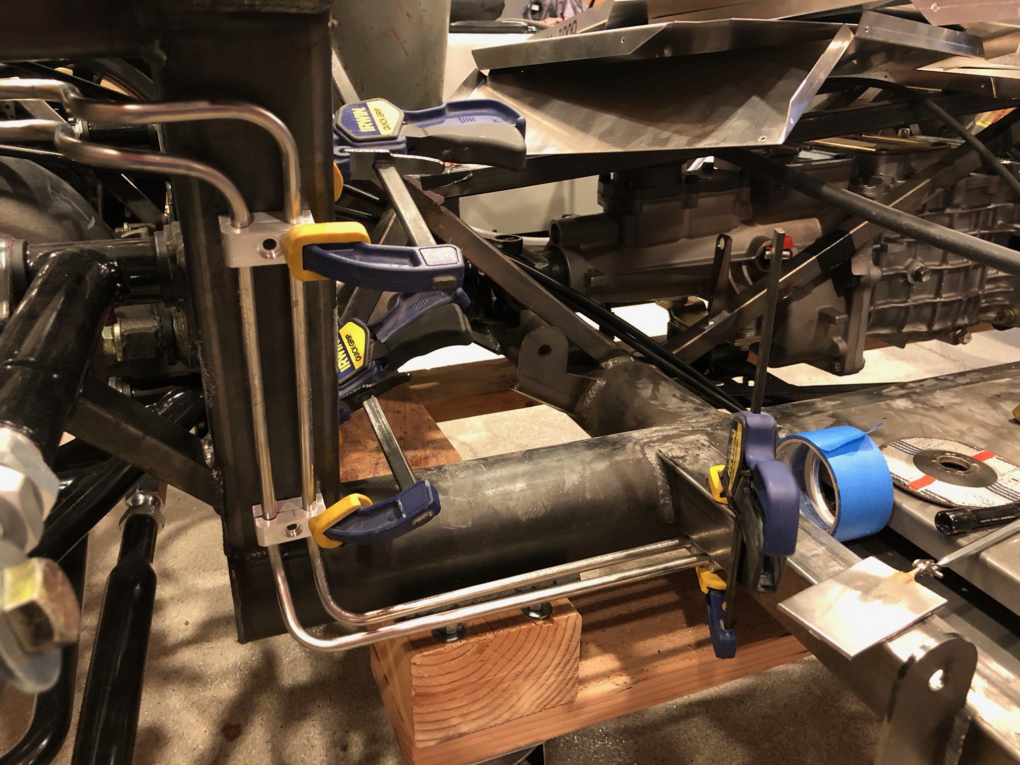
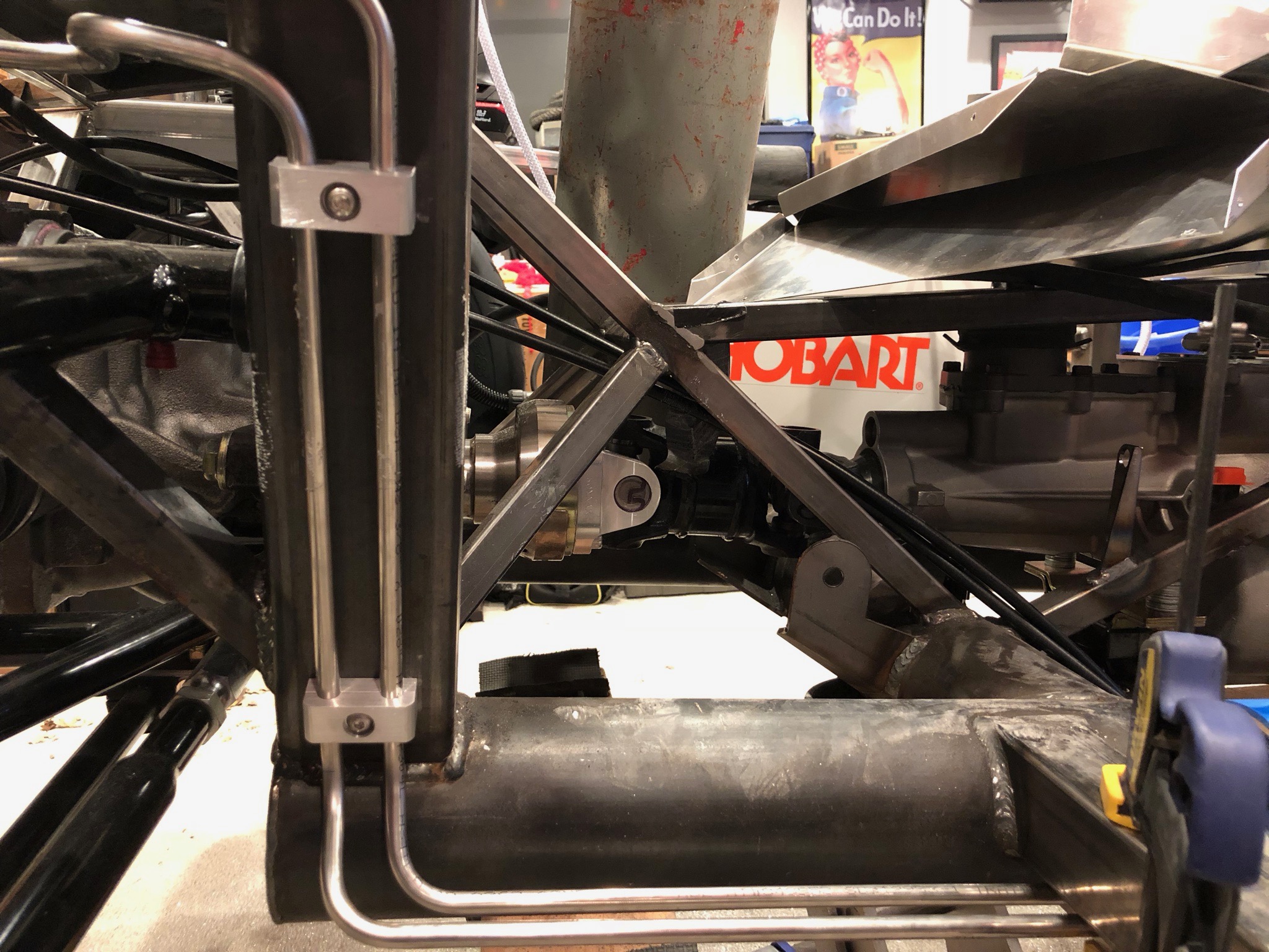
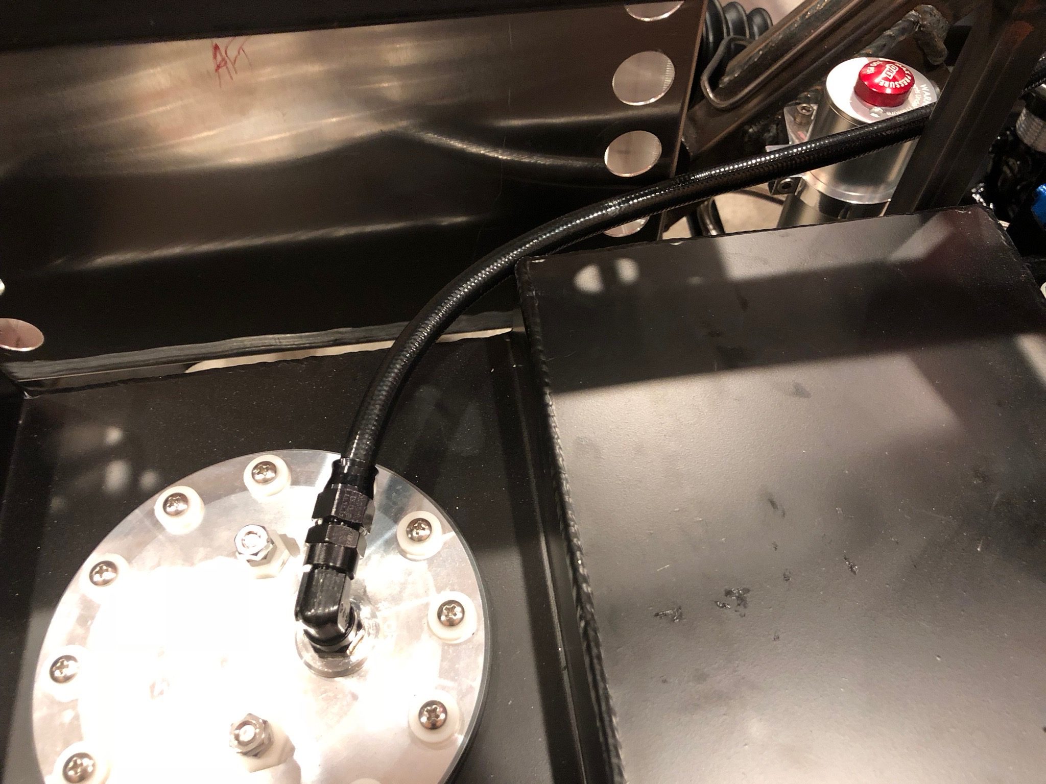
I installed fuel line armor on both the supply and return fuel lines. This is basically just a stainless steel spring that surrounds the tubing to protect against road debris.

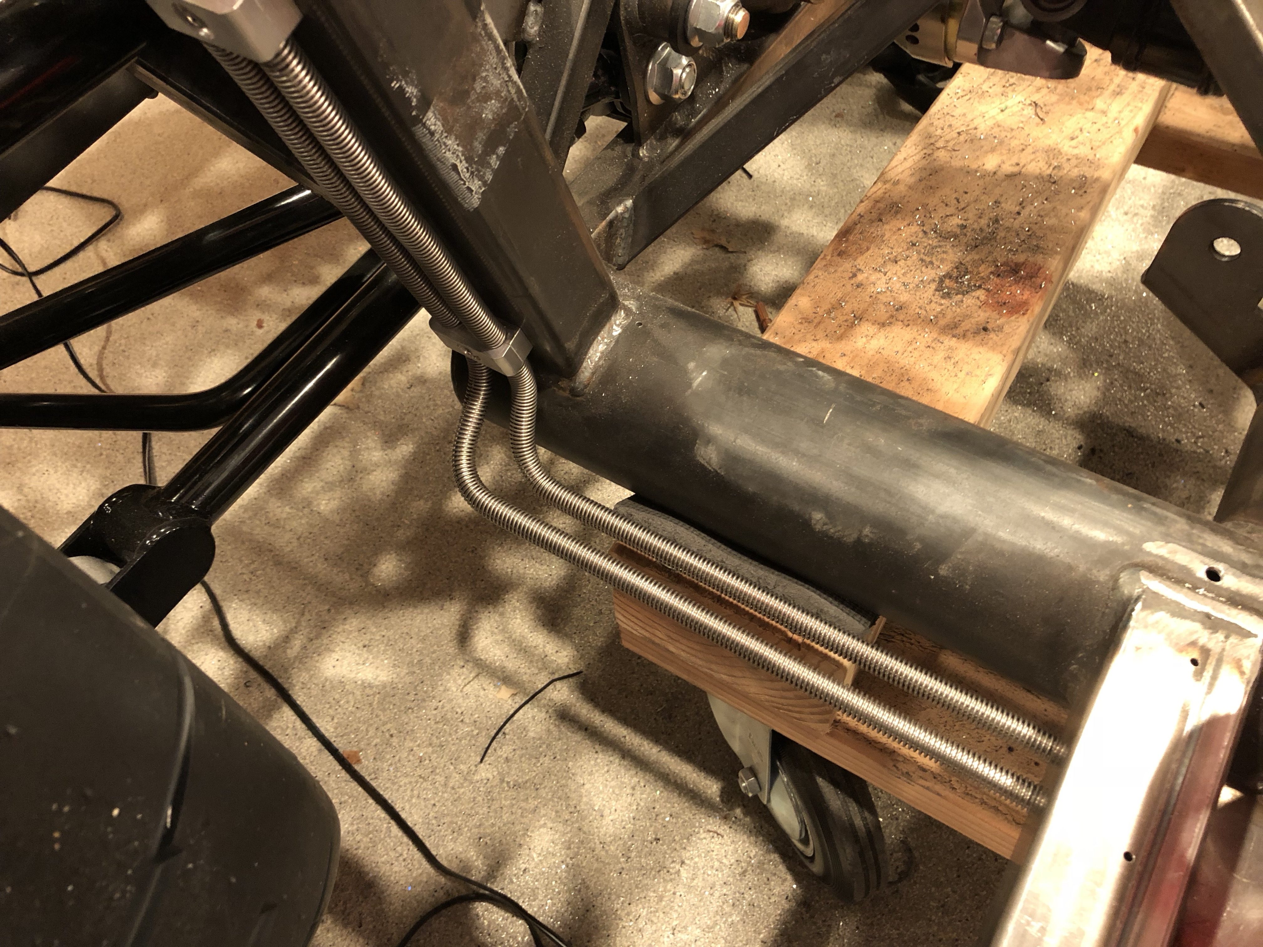
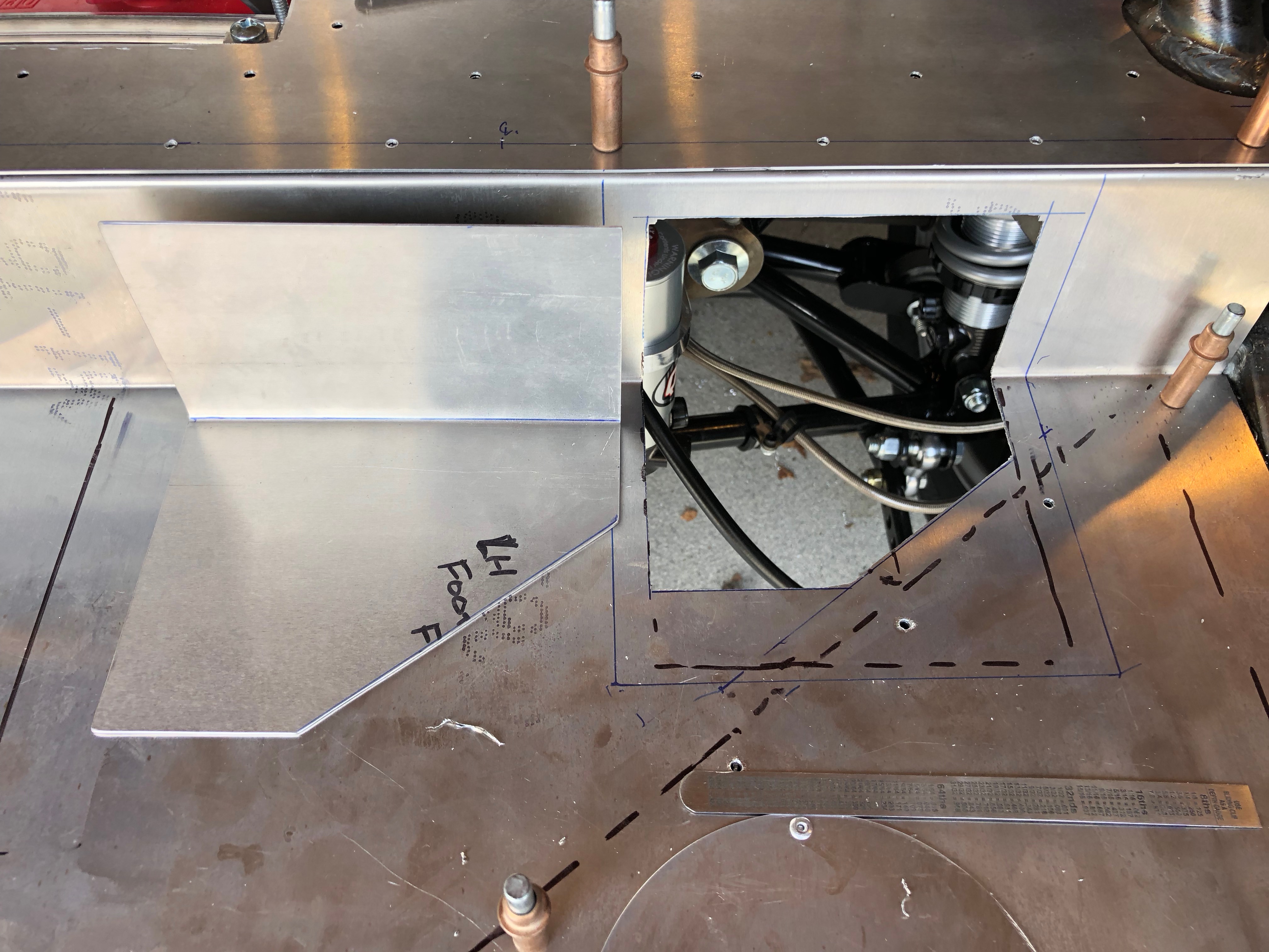
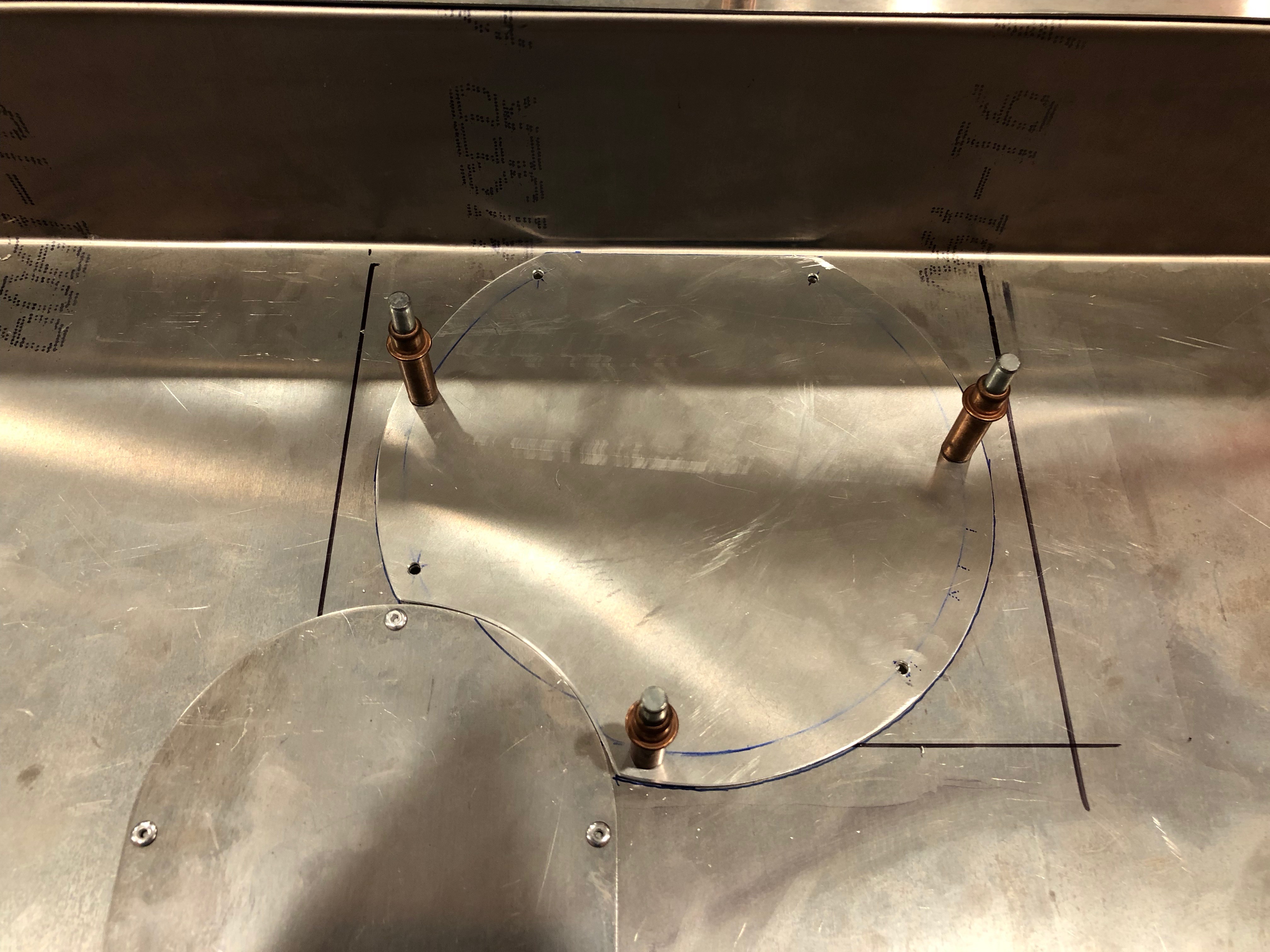
I also fabricated the forward fuel lines that come up through the hole in the floor. It looks like the line is touching the edge of the hole, but that’s just the armor. I may still relieve this a little more when the car comes apart for final assembly.

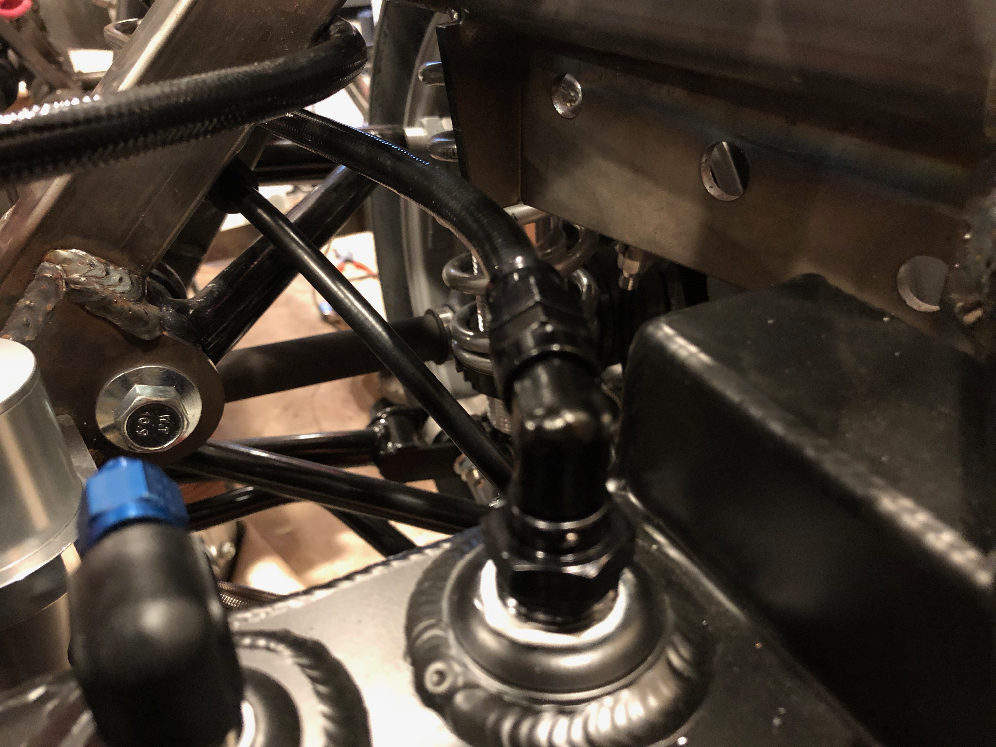
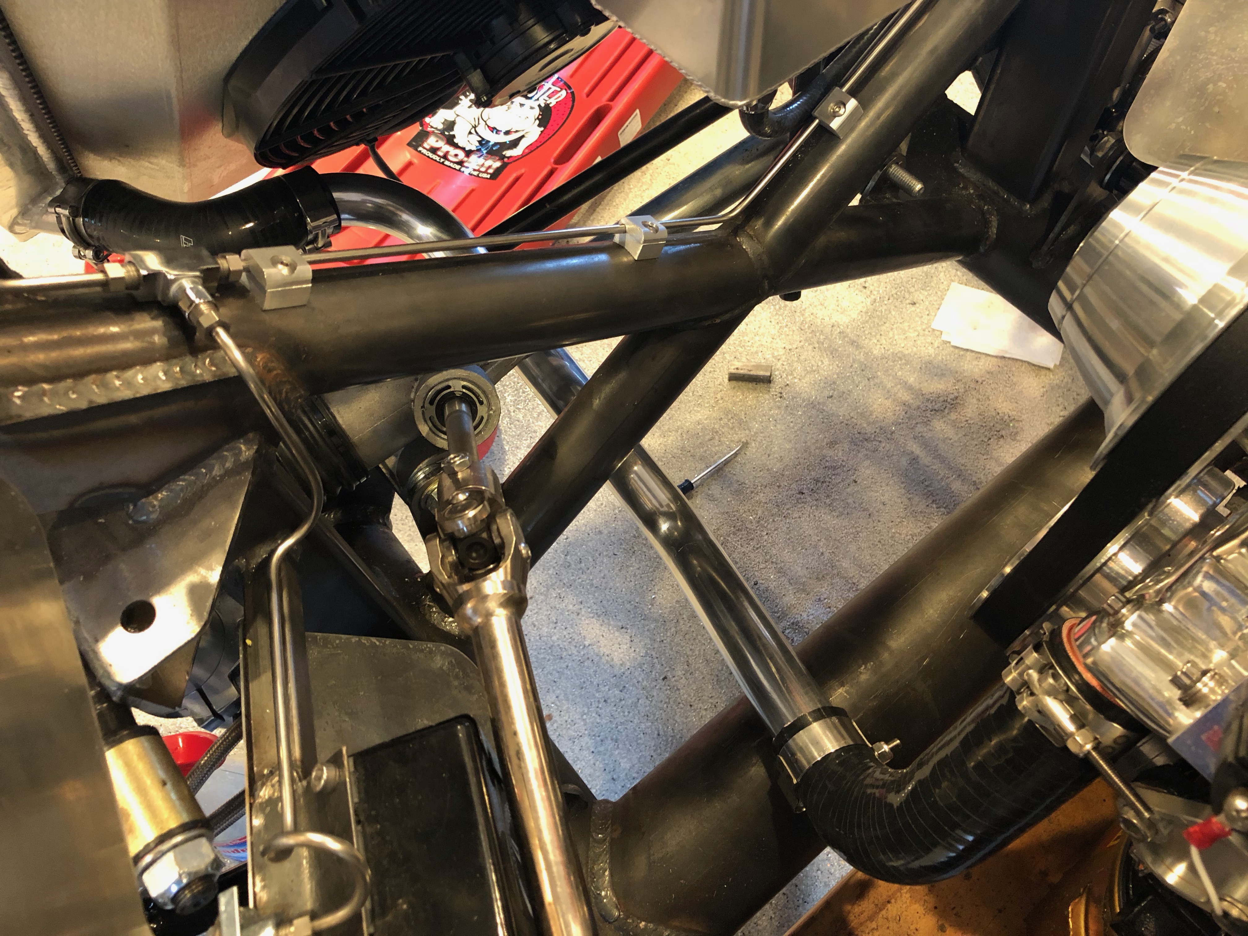
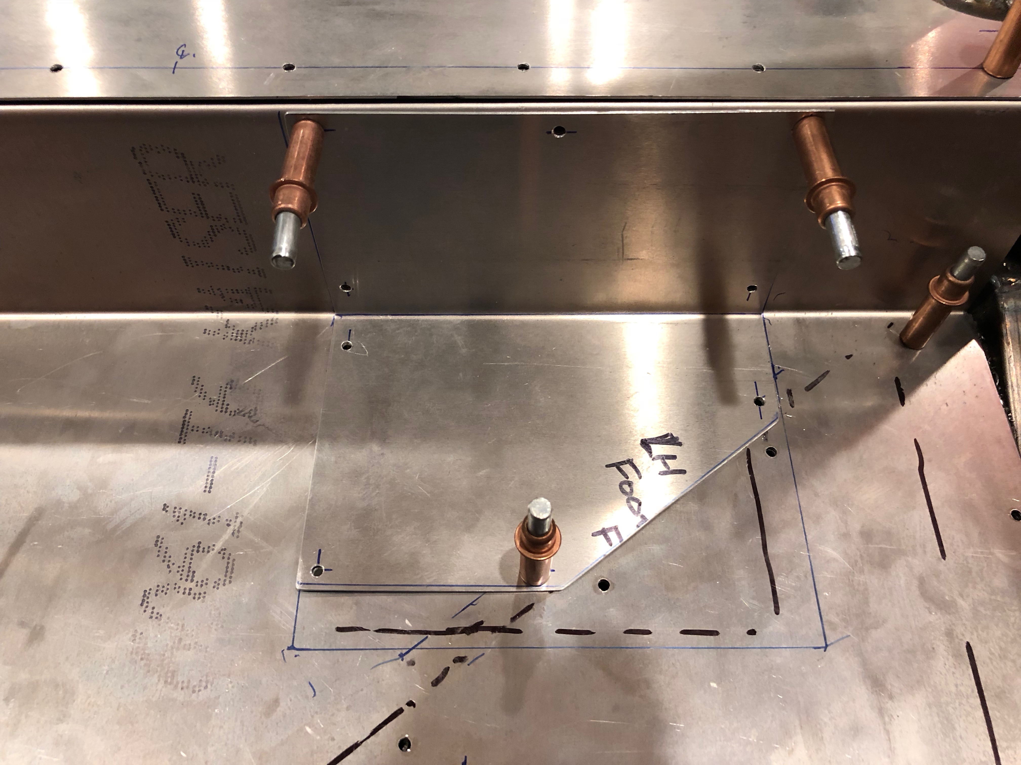
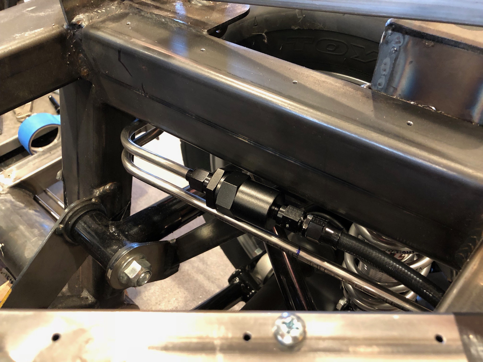
The lines come up just inside the passenger foot box. I then fabricated the final hoses that connect the fuel lines to the throttle body.

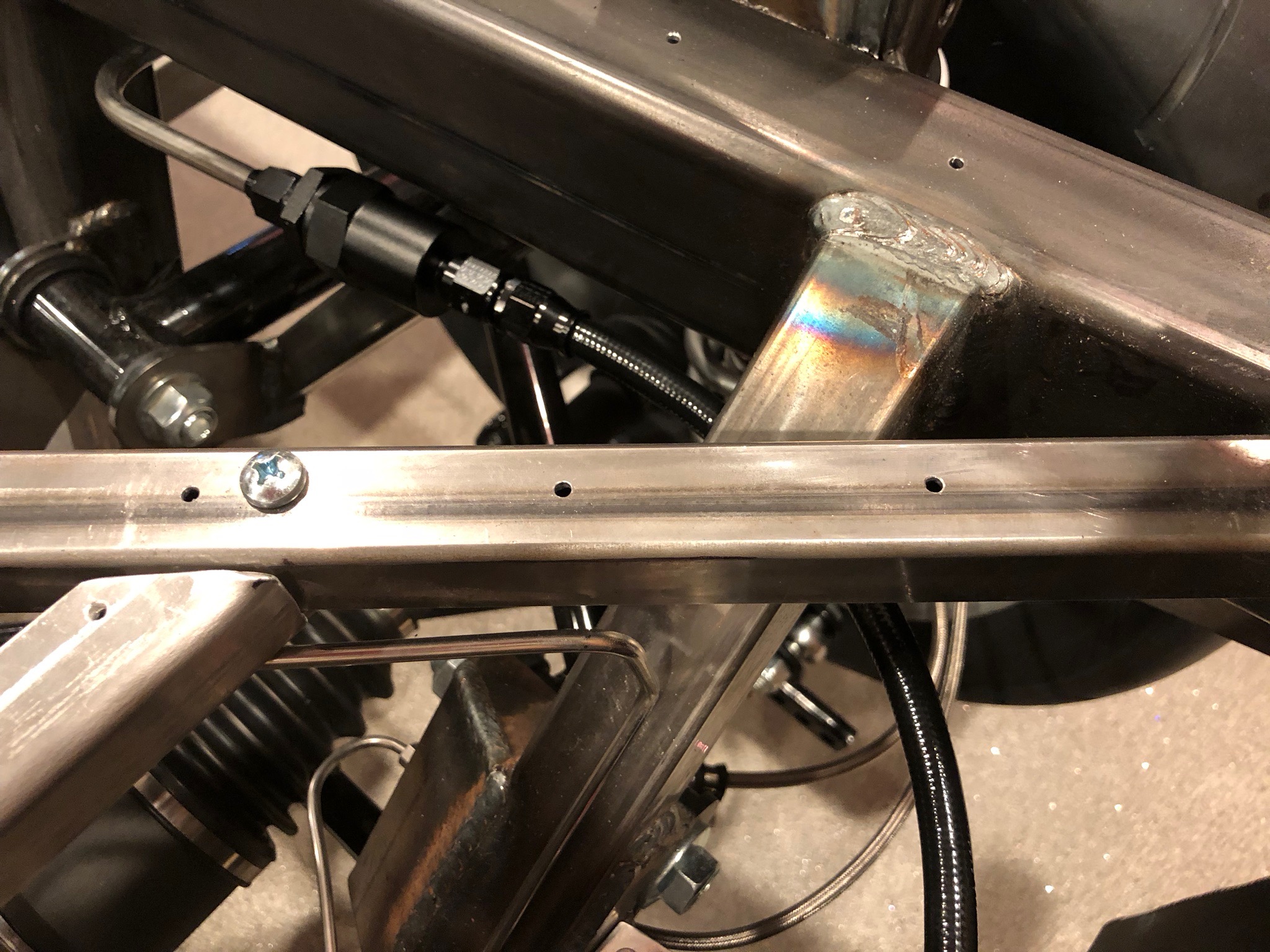
Before firing the engine again, I undid the two fuel fittings at the throttle body and connected them together. I run the fuel pump for a minute or so to flush any debris out of the lines. There shouldn’t have been much since I blew out all of the lines and hoses with compressed air, but I’d rather have any small particles end up back in the fuel tank (upstream of two fuel filters) rather than stuck in the throttle body.

After a final check, we restarted the engine for the first time in about four months. It looks like all of the systems are working well together.

Resumed Work on Fuel Lines

I resumed work on the fuel lines tonight and got started by fabricating the fuel return line. I used a special 90º swivel fitting with 1/2 NPT threads instead of installing a 1/2 NPT to -6 AN adaptor and then a 90º AN fitting on the hose becase this doesn’t stick up as far. Even this sticks above the top of the fuel tank by nearly 1/2″, and the trunk floor is only 3/4″ above the top of the trunk. I made the hose about 1/2″ longer than necessary to put a small bend in it. This will prevent the hose from being pulled tight if the tank moves around a bit.

The return line connects just below the supply line with the filter.

The fuel lines run just outside the right main 4″ chassis tube. I briefly considered bringing them up in front of the passenger foot box, but that would put them very close to the right exhaust header. Instead, I marked and began cutting a hole in the passenger foot box floor to bring the fuel lines up farther back and farther away from the exhaust headers. The cut lines follow the inner wall of the passenger foot box. I’ll fabricate some flanges to rivet the wall to the floor along these edges.

I cut the fuel lines just aft of this hole and flared them for some fittings. I’ll fabricate some shorter tubing sections later to run from here up behind the engine in the engine bay. There will be hose segments connecting the rigid tubing to the engine to allow for engine movement.

Reverse Switch, Fuel Filler, Coolant System and Electrical System

The Tremec reverse light switch looks like it has threaded studs, but these are just ribbed and use some oddball connector.

I removed it and replaced it with a GM 14014559 switch which uses a standard Weatherpak connector.

I installed the fuel hose and fuel cap just to prevent fumes from escaping and keep debris out of the tank.

I also got some new 90º silicone hoses from HPS Silicone Hoses. The forward one is 1.5″ on both legs and the aft one has one 1.5″ leg and one 1.75″ leg (for the water pump). After tightening the hose clamps, I filled the coolant system with coolant and filled the reservoir about half-way.

Finally, I printed some heat shrink tubing labels and added them to all of the wires on the load cells. Here’s the front load cell. Since the load cell is on the right side of the vehicle, I positioned the labels to be readable from above on that side.

I installed the rear load cell wire labels upside down since these can only be accessed from below once the trunk floor is installed.

Differential Vent, Battery Box, Fuel Tank and Electrical System

I finally received the differential vent fitting I’ve been waiting for. It’s a press in fitting (unlike the threaded fittings used on the solid axles). I used some high-temp thread locker and drove it in, then fit a vent riser with check valve at the top. I’ll use an adhesive zip-tie base to secure the top of this and keep it upright.

After installing the battery box, I reinstalled the battery (hopefully for the last time before the go-kart stage).

My dad and his friend Larry helped me lift the fuel tank and get the straps installed.

Jenn came out and we spent some time working on the electrical system. She crawled underneath the rear end so that she could hook up the power wire to the mega fuses.

The power wire connects to the front of the buss bar (at the top of this picture). This is looking up from below.

The wire is secured with an adel clamp just in front of the mega fuses and then follows the forward battery box support to the right side of the battery box.

There, it drops down and hooks to the right side of the inRESERVE solenoid.

I installed the power wires in the rear load cell that will connect to the mega fuses. I left them a little long for right now until I have a better idea where all the wires will route in this area.

I also installed the power wires in the front load cell and snaked them down through the transmission tunnel.

The run along the upper left side of the transmission tunnel…

…where they follow the left parking brake cable back to the mega fuses. These are also left long for now.

Jenn then installed the inDASH MAX box on the aft side of the firewall.

It’s installed just to the left of the mastercell.

Trunk Aluminum, Fuel Tank Stabilizers and Rear Brakes

Before I can install the fuel tank for good, I also needed to wrap up the trunk aluminum. I had previously drilled the upper trunk floor, but I never did the same for the lower trunk floor. I started by removing the tank (hopefully for the last time before the final reassembly). I needed to do this so that I could mark the chassis tubes on the underside of this sheet. After laying out all of the holes, I drilled the sheet to the chassis tubes. You can also see that there is a row of rivet holes tying the upper trunk floor to the lower trunk floor.

With the lower trunk floor in place, I cut and bent a piece of scrap aluminum to make the access panel cover for the fuel sender and fuel return and vent fittings.

I drilled this to the floor with a #30 bit for now. I’ll open these up for the right size screw before installing nutplates.

I also cut out and drilled an access panel cover for the fuel pump and supply fittings.

The fuel tank is narrower than the cavity in the chassis that it fits within, but I don’t want the fuel tank to be able to slide from side to side. To prevent this, I drilled a 1/4″ hole in the lower diagonal tube on the inside face and welded on a 1/4-20 nut.

I threaded a leveling foot with threaded stud into the nut. I had previously bonded a piece of the same reinforced rubber sheeting onto the foot where it will contact the tank.

You can see on the other side that there is a run nut threaded onto the shaft as well. Once the tank is installed, I can tighten the foot against the tank and lock it into position with the jam nut.

Before reinstalling the tank, I wanted to wrap up the rear brakes. I started by adding a brake line clamp on the right diagonal tubing. Unfortunately, when I was trying to wrap up the other end of this piece of tubing, I botched the flare. I don’t think the tubing is salvageable, so I’ll probably have to fabricate a new piece.

Fuel Tank Straps and Trunk Aluminum

After reshaping the fuel tank straps to better fit the angles of the new fuel tank, I used some contact adhesive to bond some strips of reinforced rubber sheeting to the inside surfaces where it will contact the tank.

While waiting for those to cure, I installed the outer trunk side skins. After marking the chassis tubes, I laid out for the rivet holes and drilled them to the chassis.

Installed Fuel Line Clamps

I received a new tool for Christmas from my awesome wife. I have a small hand tool that was fine for setting aluminum rivet nuts, but for the car, I really need to set steel rivet nuts and I knew that it wouldn’t do. This Astro rivet nut drill adapter is highly recommended and has great reviews online.

It’s a really nicely built tool. The body is machined from a solid block of aluminum and it has all chromoly internal components and mandrels for maximum durability. A cordless drill with a clutch is attached to the shaft on the right side and used to set the rivet nut.

It has mandrels for 8 sizes of SAE and metric rivet nuts, but I’m only planning on using three sizes on the car 8-32, 10-24 and 1/4-20 (arranged from top to bottom). I set some samples in a piece of scrap steel to determine the correct torque setting on the drill. The 8-32 rivet nuts are a little short for this thickness of steel, but I’ll probably mostly use them in thinner metal.

I’m using some billet aluminum clamps from Lodestone BilletWorks to secure the fuel lines to the chassis. I clamped a few on to determine where to drill for the rivet nuts.

After drilling and setting a couple of rivet nuts, I secured the clamps on the vertical support so that I could determine the final position of the clamps under the passenger seat.

I drilled and installed a rivet nut in the horizontal tubing behind the passenger seat. I used the measurements from this hole to drill the corresponding hole in the horizontal tubing in front of the passenger seat.

I’m not sure yet whether two clamps under the passenger seat will be sufficient or if I’ll need to add an additional clamp or two. The 3/8″ stainless tubing is pretty stiff, but it sounds like other builders space them closer together (and some state regulations require it).

Received Tubing Clamps

We also received some tubing clamps from Lodestone BilletWorks. These clamps are for the 3/8″ fuel supply and return lines.

I also ordered a bunch of single, 3/16″ clamps for the rear brake line. I may need more of these because I need to put them closer together because of the smaller size of the tubing.

I also ordered four of these with a 1″ radiused back to support the front brake line where it follows the x-frame.

Fuel Hardlines

I straightened a 20′ roll of 3/8″ stainless tubing and then cut it in half. I made a few bends to allow it to run under the passenger seat just outside of the 3″ round tubing.

I flared the end and added a flare nut and sleeve. The fuel filter will mount here and be supported by a large adel clamp.

I fabricated a fuel line with a -6 ORB 90º connector on one end that hooks to the fuel pump.

It snakes forward and connects to the fuel filter.

I then fabricated the return line so that it parallels the supply line under the seat and up the diagonal support.

It will run just under the fuel filter and will have a fitting where I’ve made the mark. A flex line will connect it to the return fitting on the tank.

Fit Fuel Tank

I test fit the fuel tank because I need to cut new access panels in the lower trunk floor. The fuel sender sticks above the top of the tank, so I needed to shift the tank most of the way forward and slightly left of center in order for the sender to clear the right diagonal square tubing.

I temporarily supported the tank with my pneumatic stool and removed the straps so that I could install the lower trunk floor.

With the floor installed, I marked the location of the new access panel for the fuel pump. I’ll probably make this slightly bigger so that I can remove the fuel pump through the hole if that ever becomes necessary.

I also laid out the hole for the access panel that covers the fuel level sender, fuel return and vent fittings. This access panel will wrap up the vertical portion of the lower trunk floor since the plumbing fittings are forward of this surface and would be difficult to access only through the lower portion of the hole.

Since I don’t need these access holes, I made sure the rivets wouldn’t interfere with the 3/4″ square tubing below and then drilled and riveted these plates in place.