Strut Hoses and Trunk Aluminum

The parking brake cable rubbed against the strut reservoir hose, so I used a zip-tie and a short piece of plastic hose (extra from the brake bias adjustment cable housing) to tie them together while keeping them separated.

The hoses connecting the front struts to the reservoirs have a hose that is too long for our application. I had the hoses just making a gentle bend between the two and it went so high that it interfered with the upper control arm. I removed both reservoirs and put an extra bend in the hose. This places the hose completely clear of both the upper and lower control arms and should easily handle the flexing during suspension travel.

I realized that there were a couple of extra pieces of trunk aluminum that I never drilled to the chassis, so I took care of that before heading to bed.

Figured Out Seat Track Mechanism

Most builders just bolt the seats to the floor, but that won’t work for us. Jenn and I are nearly one foot different in height (5′ 4 3/4″ vs 6′ 4″), so we have to have an adjustable seat. Factory Five sells a seat track that works for the Roadster, but it only locks on one side. This won’t pass the technical inspection at some tracks, so I decided to see if I could find a seat track that has dual locks that could be made to work with the Roadster seats.

This is a set of Summit Racing seat brackets (part #G1153). It appears to be the same exact manufacturer and part as the one FFR sells, but it has dual locks. The instructions specify that the upper bracket in this picture is installed pointing the other way (rotated 180º from what is shown in this picture). This puts the handle on the outside of the seat track. Adjusting the seat would require swinging the handle even further outside the seat track which is not something there’s room for in the Roadster. Instead, I reversed that track and tied the linkage together using the extension on the adjustment arm.

I clamped the tracks to the table and spaced the front ends apart with a piece of scrap metal. This works beautifully and both sides lock and unlock together. I can’t use the included linkage (shown) since this puts the tracks too far apart, but I can easily use a piece of safety wire and fabricate a linkage of the exact right length.

Wrapped up Parking Brakes, Reinforced Chassis and Adjusted Brake Pedals

With the final location of the adjustment mechanism determined, I drilled the upper hole and installed a riv-nut. I then taped the ends of the cable and cut off the excess. I’ll replace the tape with a different cable termination during final reassembly.

The cables exit the adjuster very close to the driveshaft. I want to add additional support for the cables to ensure they’ll never make contact with the driveshaft.

I added a couple of adel clamps above the differential to ensure the cables can’t drop and come in contact with the driveshaft. There’s now no way to even flex the cable enough to contact the driveshaft.

With the shifter and parking brake in place, I trimmed and reinstalled the old cross member in the top of the transmission tunnel.

Here’s the finished transmission tunnel. I couldn’t weld the underside, but I’ll take care of that when the chassis is bare again.

I trimmed 1/2″ from the pushrods of each master cylinder. You can see that the jam nuts are nearly bottomed out on the shafts.

This moves the pedals forward another 2″ or so. They now sit about 5.75″ forward of the firewall. If this isn’t sufficient clearance, there’s plenty of adjustment to move them farther away from the firewall.

I then installed the adjustment cable. I left a section without the housing to allow a tighter bend radius. I was worried that this was going to be too tight of a bend and that I was going to have to go through the sidewall of the footbox and into the engine compartment, but this works very well.

I installed the other end just to the right of the steering shaft. I could only drill through the lower two holes, so I added an adel clamp to further secure the assembly. It’s plenty rigid, especially for the infrequent use this will see.

Finally, I installed the appropriate label to mark the direction of rotation necessary to achieve the desired biasing. I won’t be able to see the label from the seat, but it’s pretty easy to remember that right is rear.

Installed Parking Brake

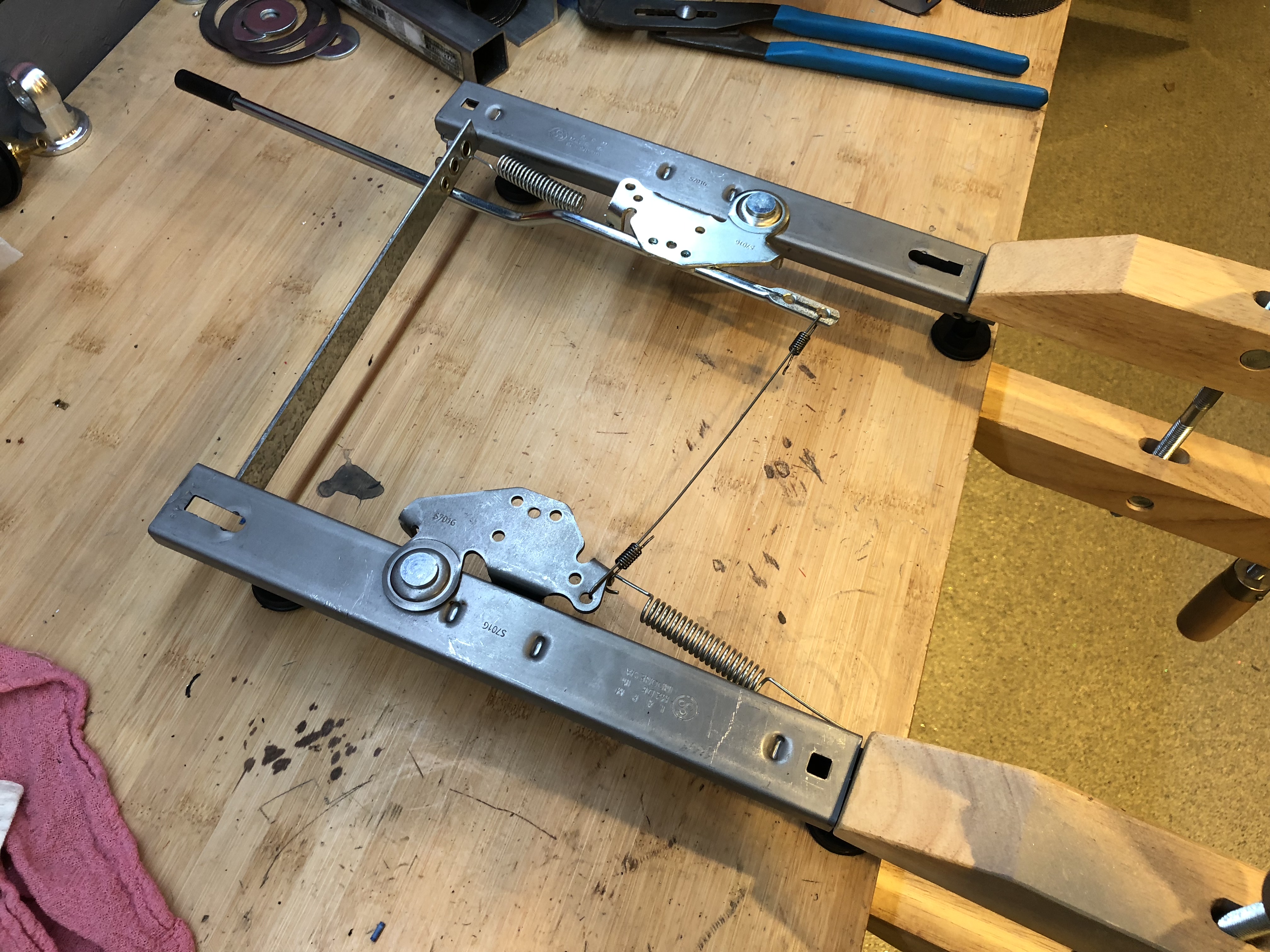
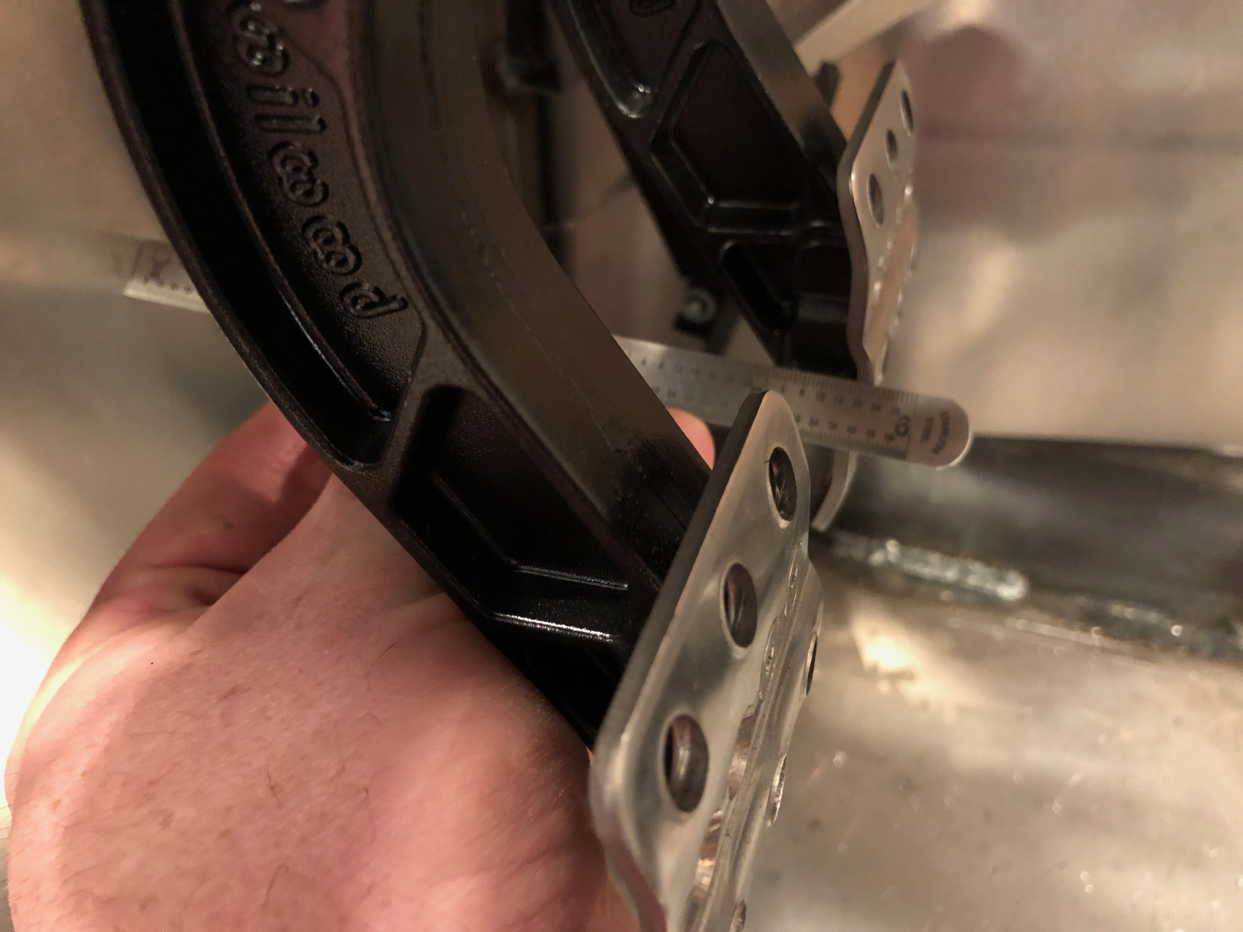
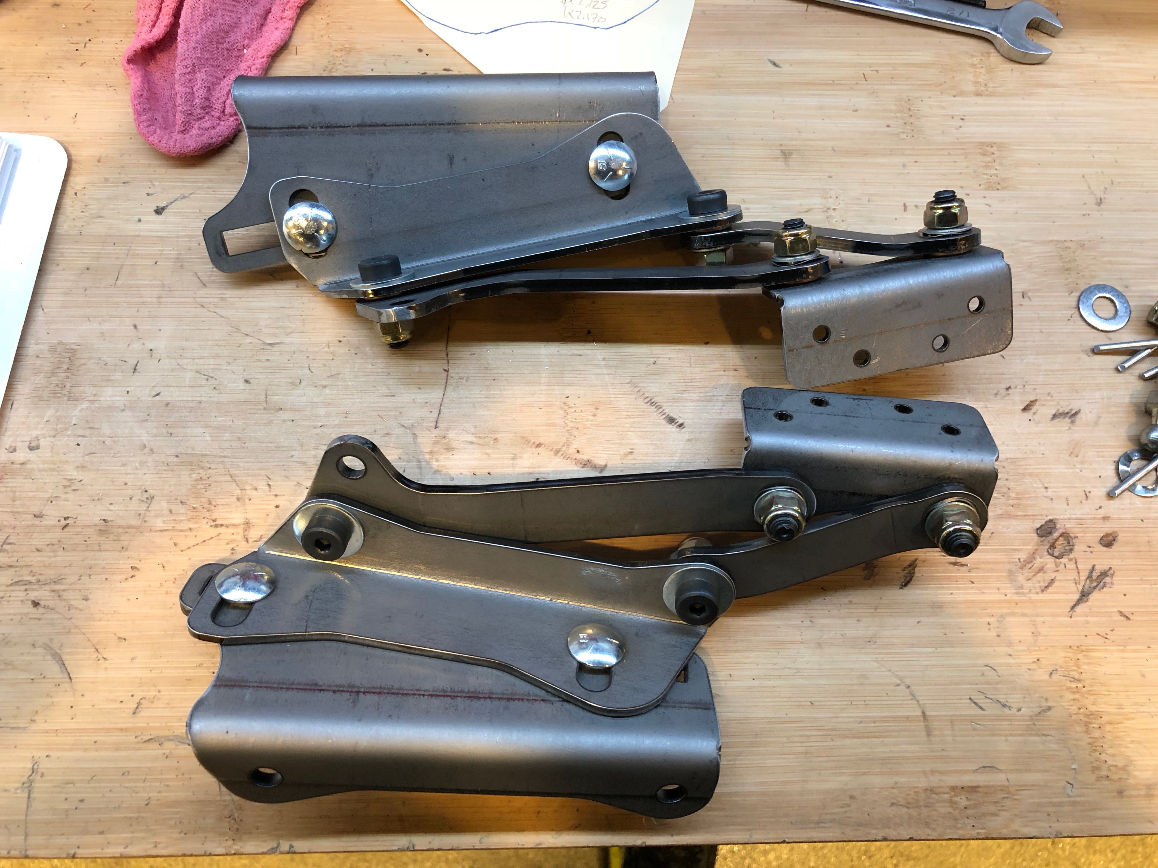
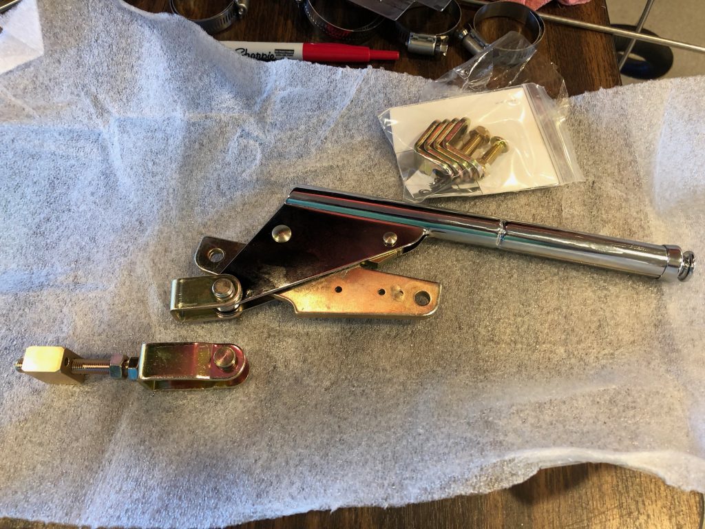
I’ve been holding off on installing the parking brake until the gear shift was relocated. With the gear shift in its final location, I can now determine the final location of the parking brake lever. I picked up a Lokar hand brake from Summit Racing to replace the unit from Factory Five. It came preinstalled with a simple bracket, but the Wilwood universal parking brake cable kit came with the adjustable bracket shown at the bottom left. It was a simple matter to swap this bracket out.

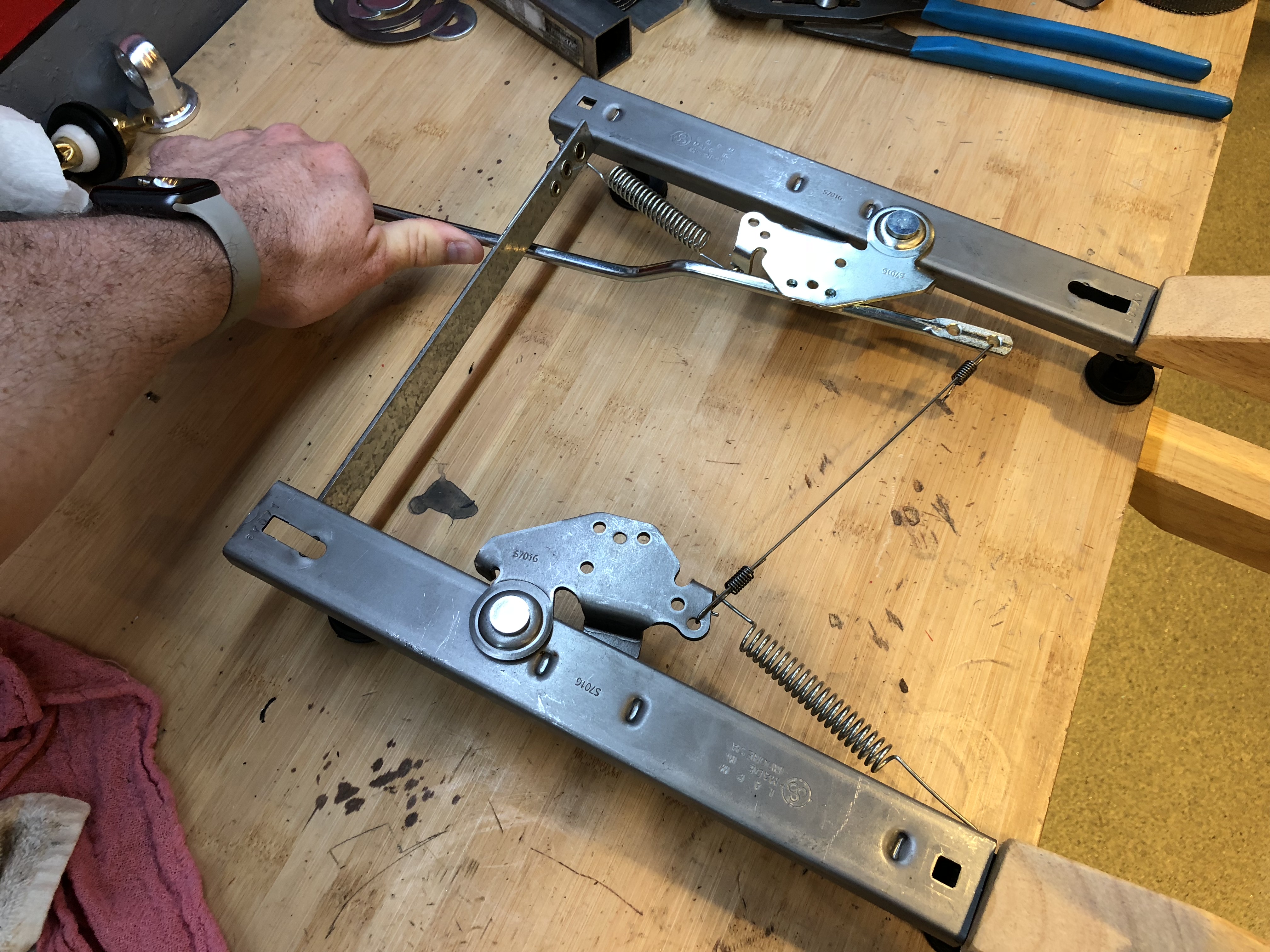
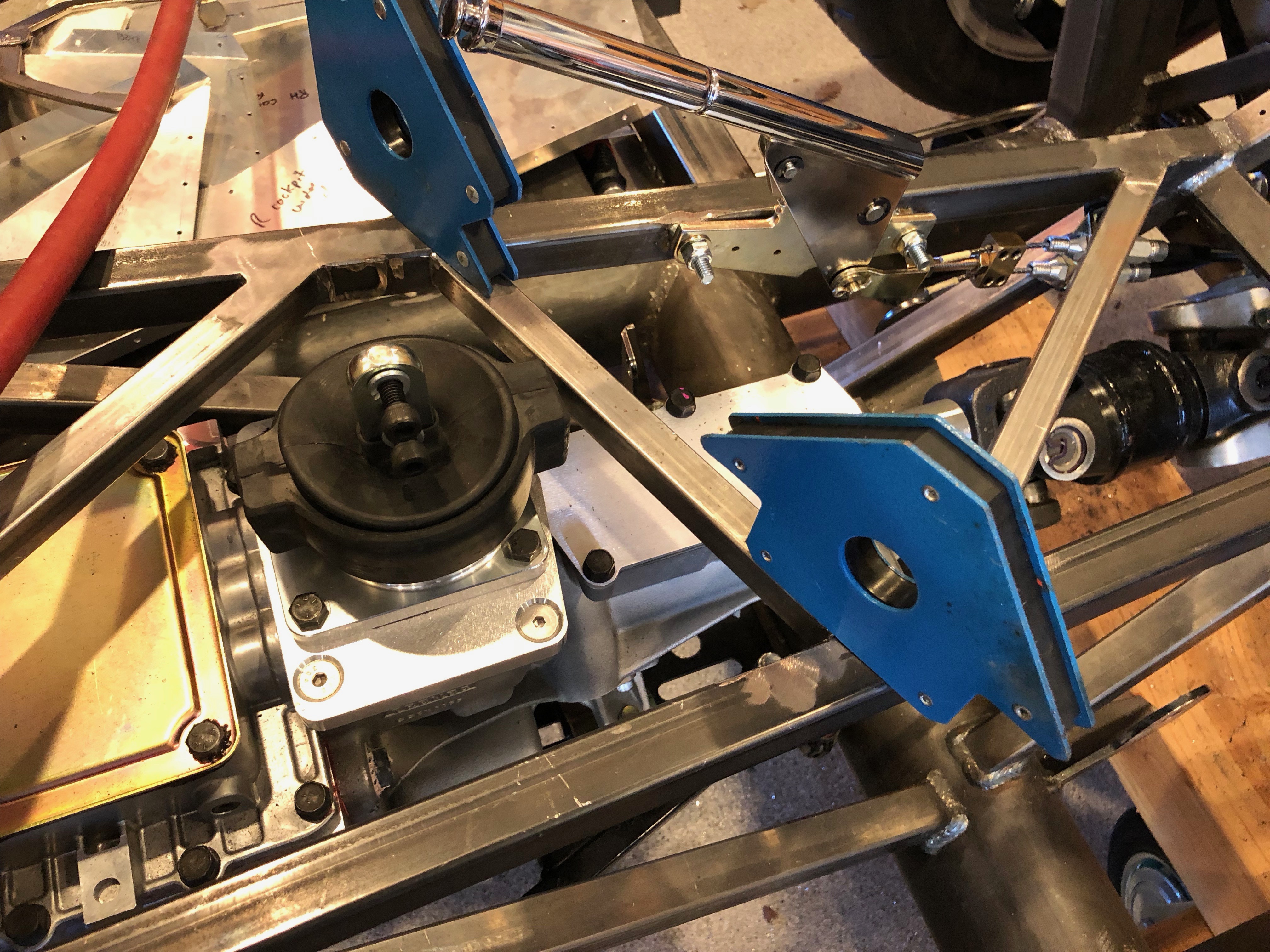
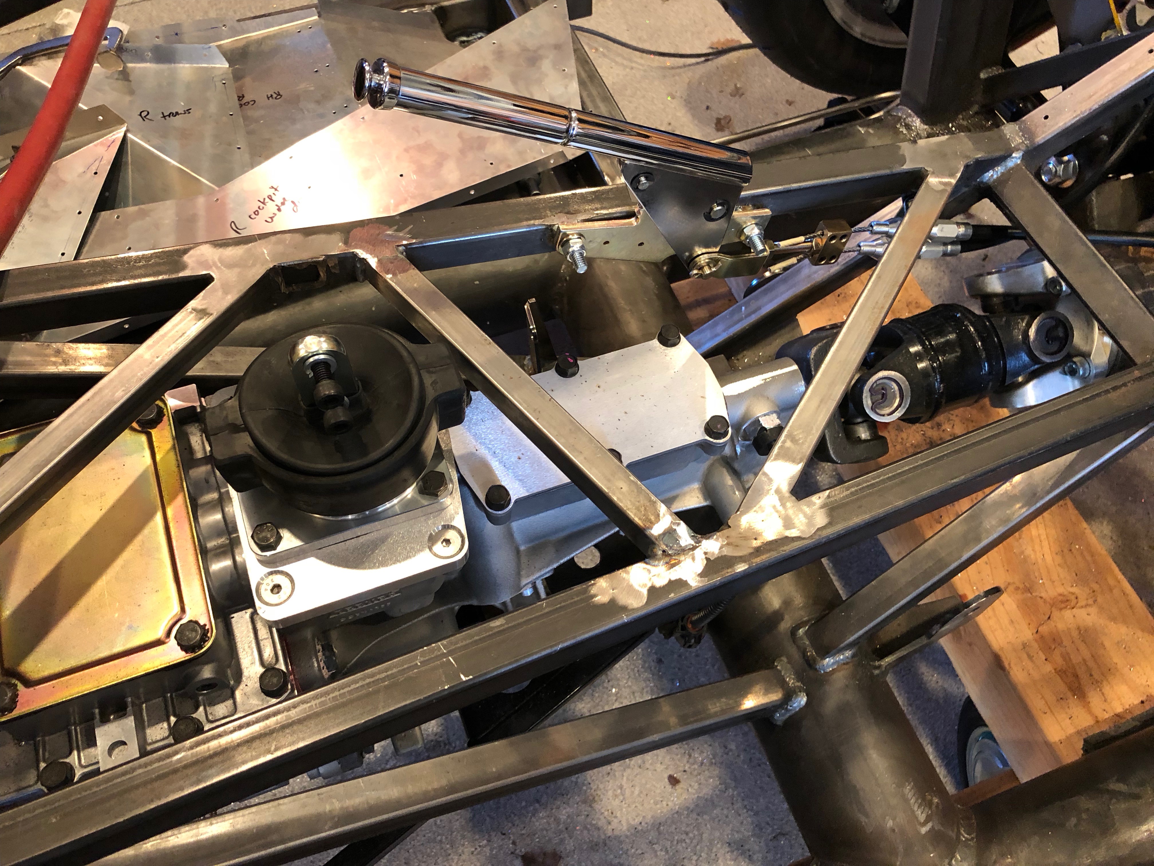
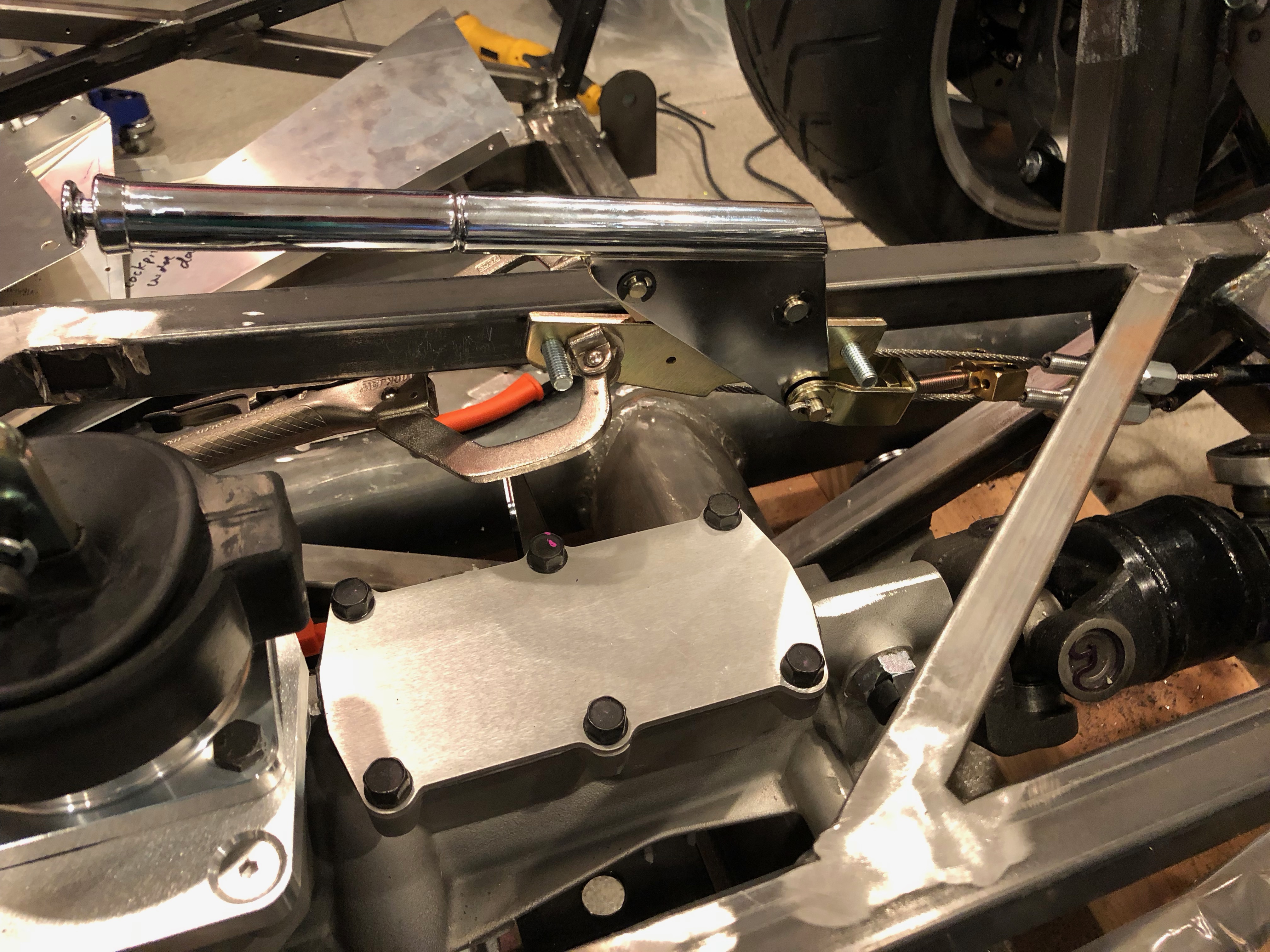
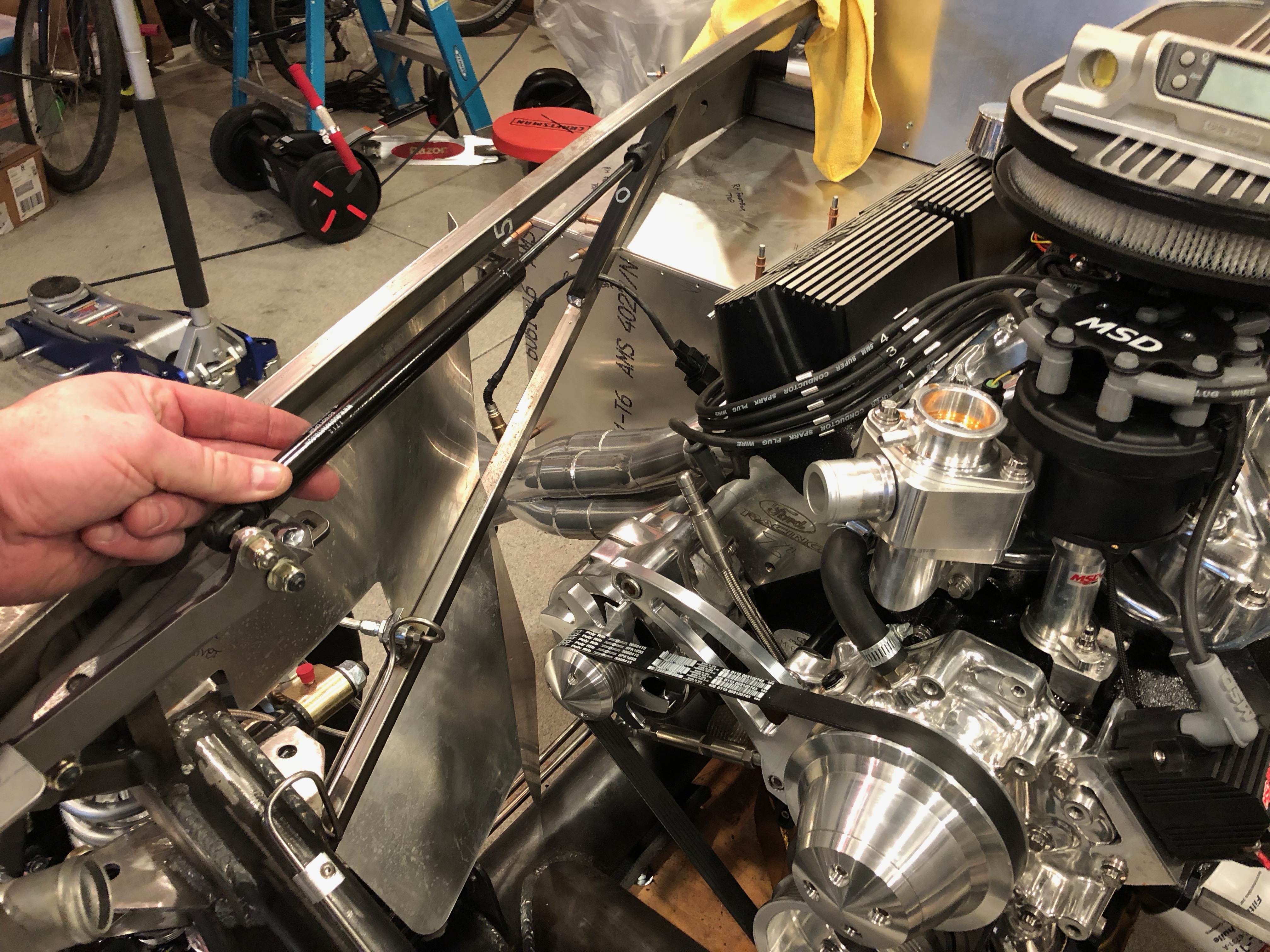
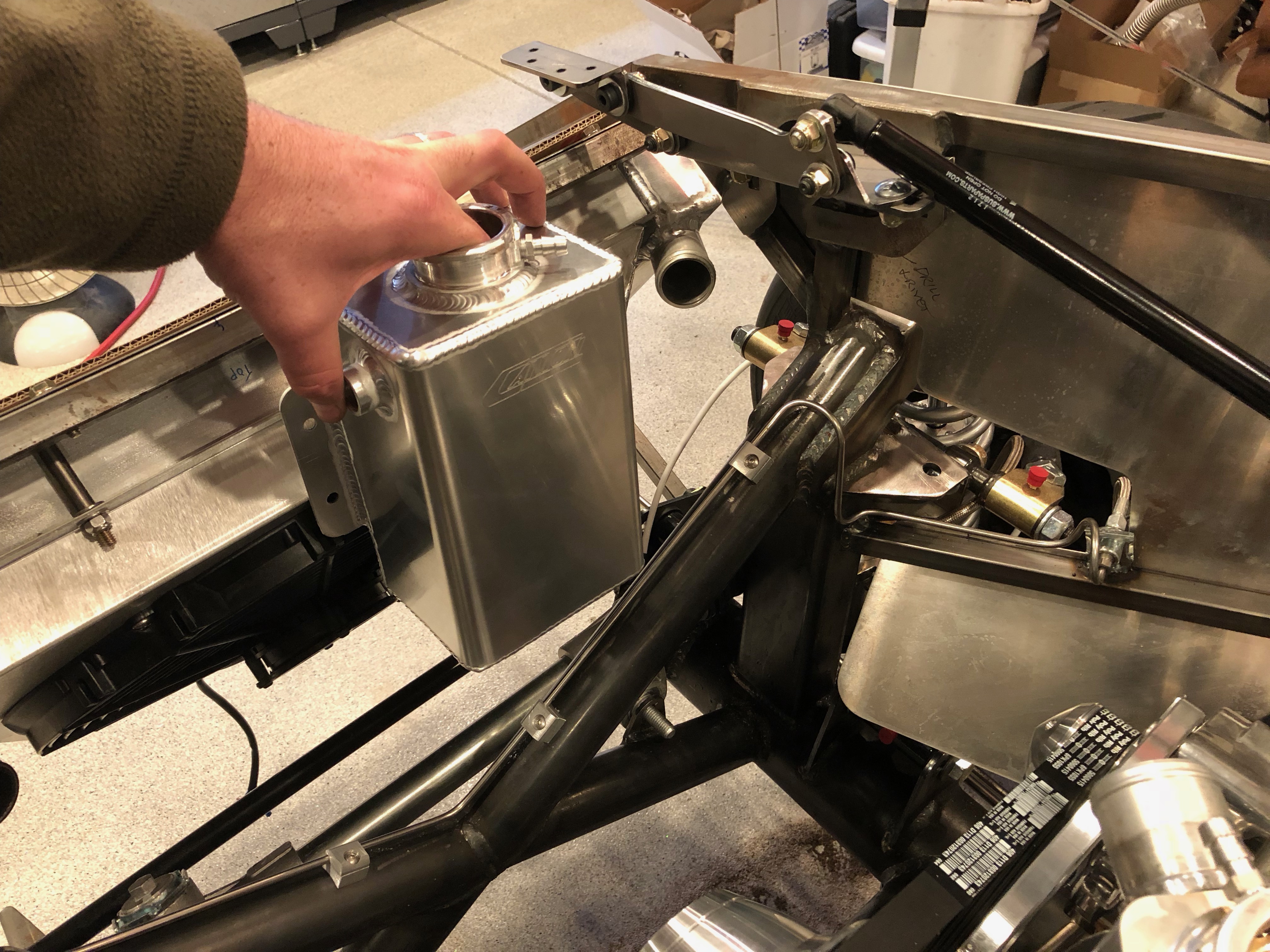
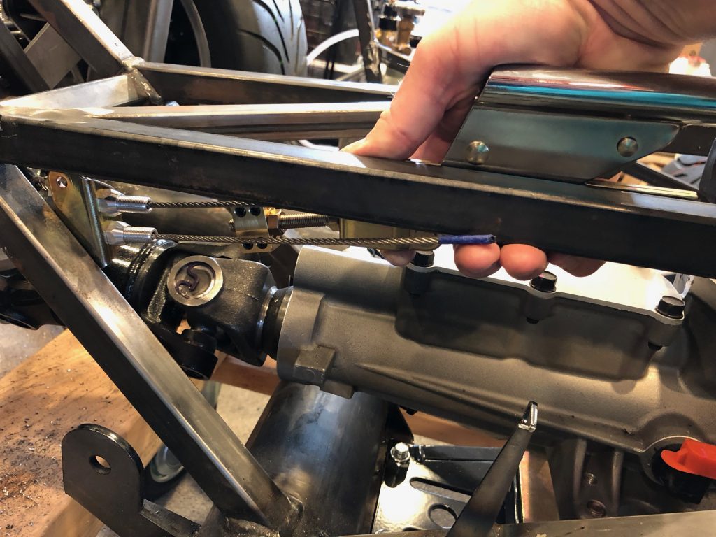
I temporarily positioned the parking brake handle and the adjustment mechanism that secures the end of the cable sheath.

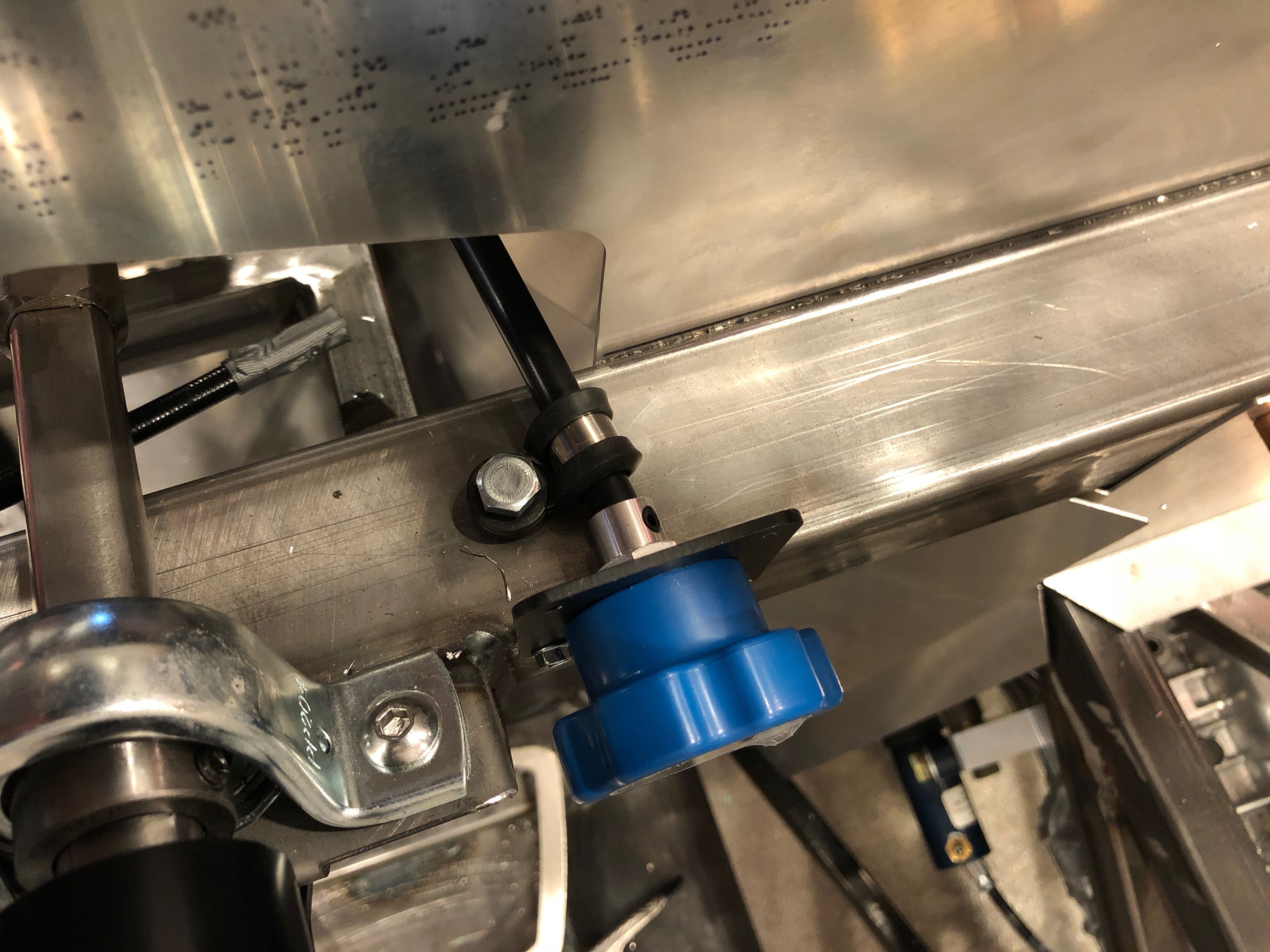
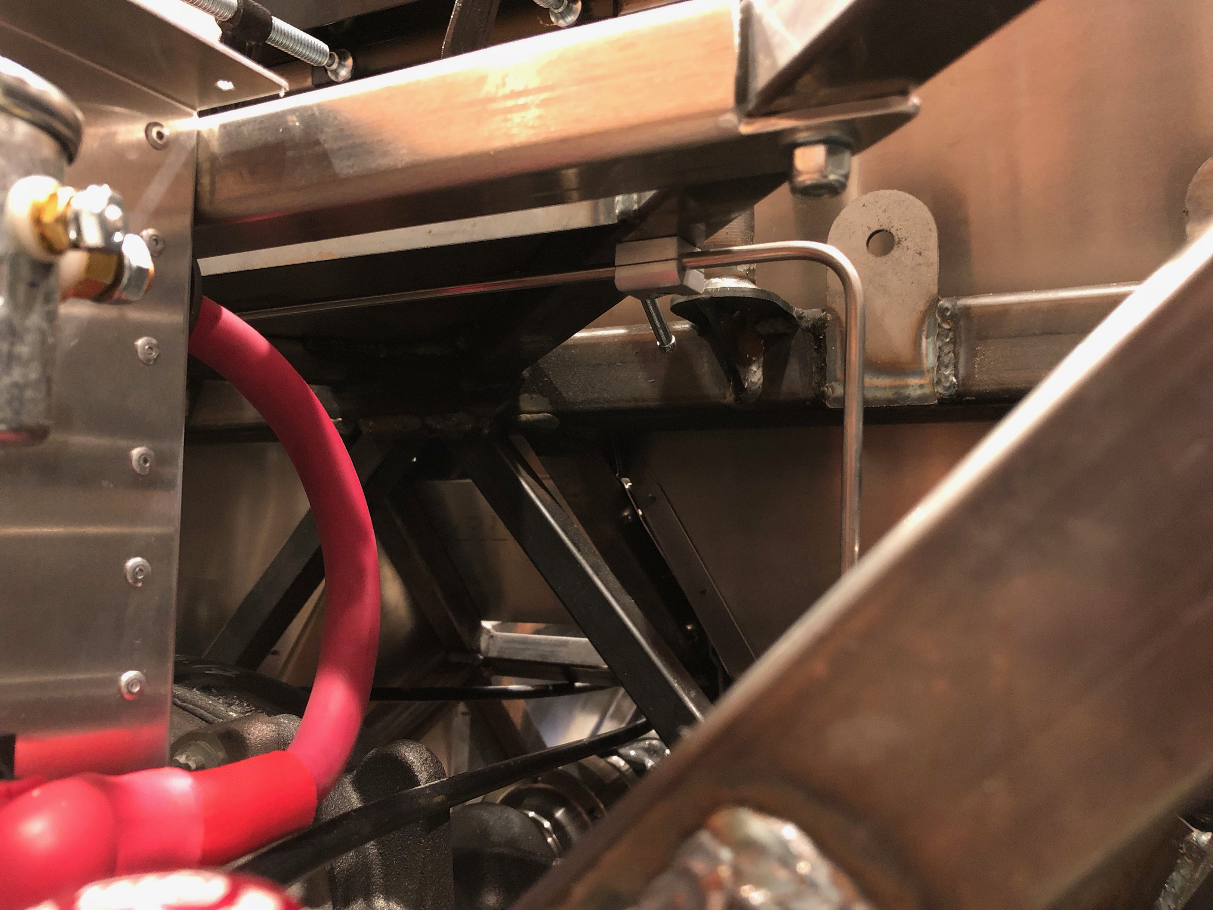
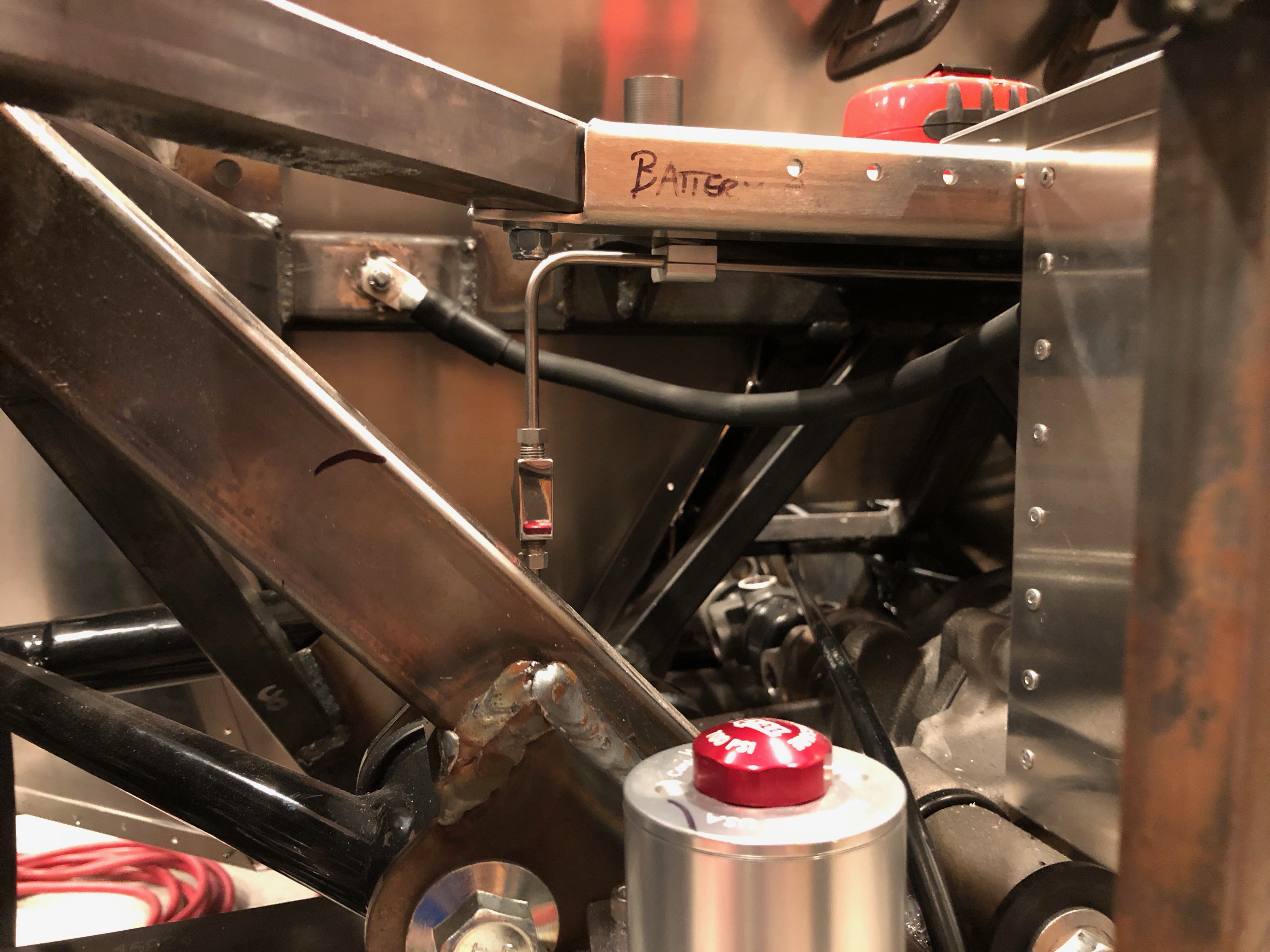
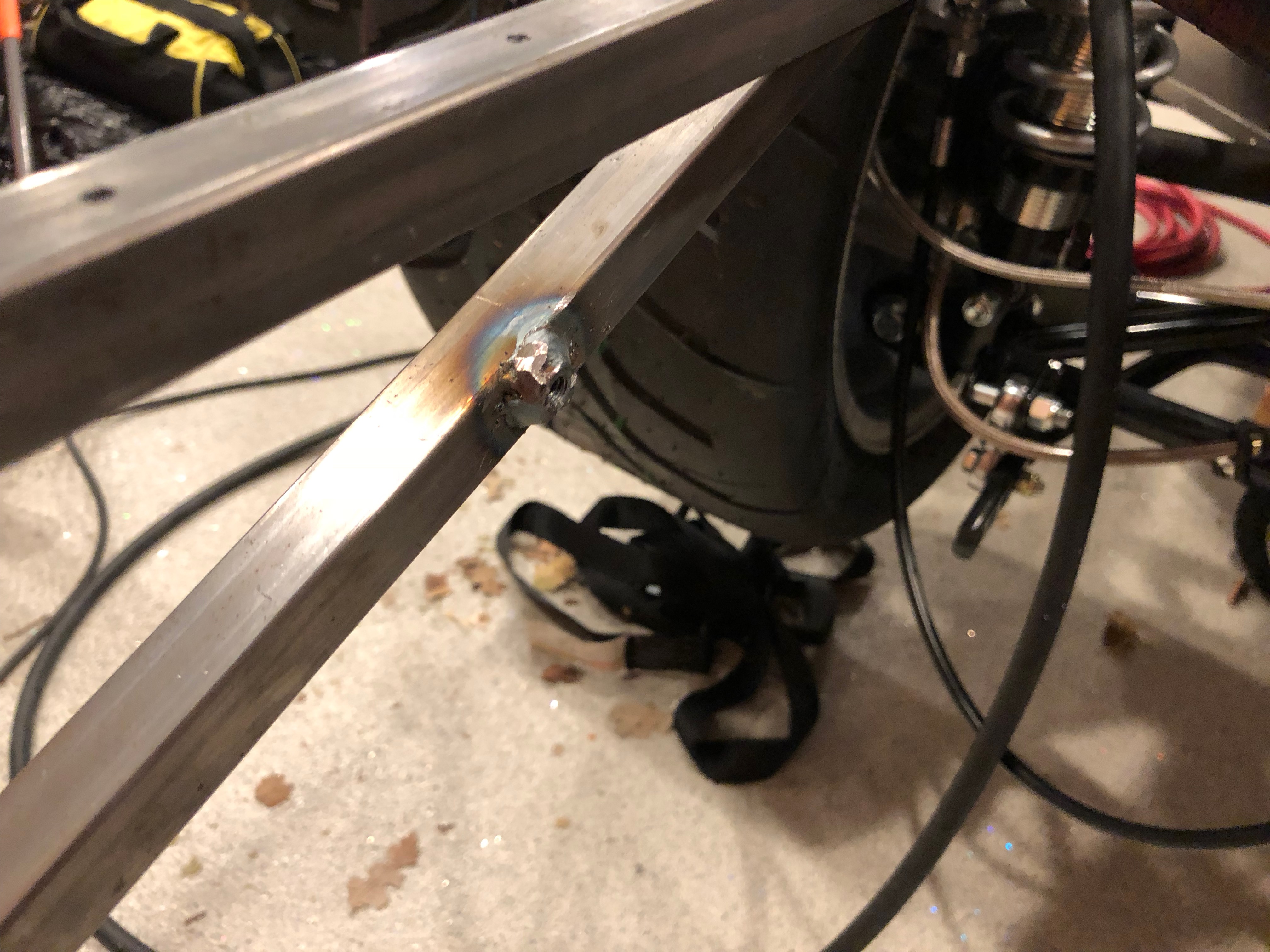
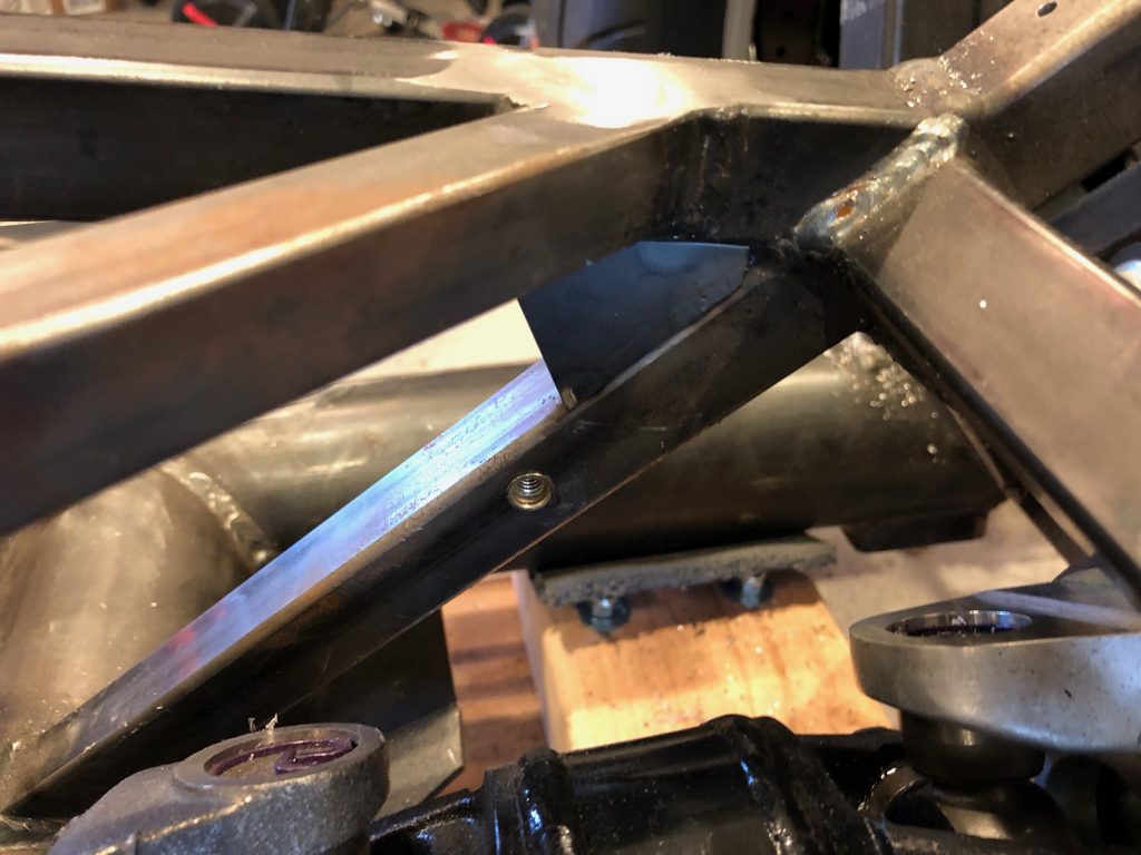
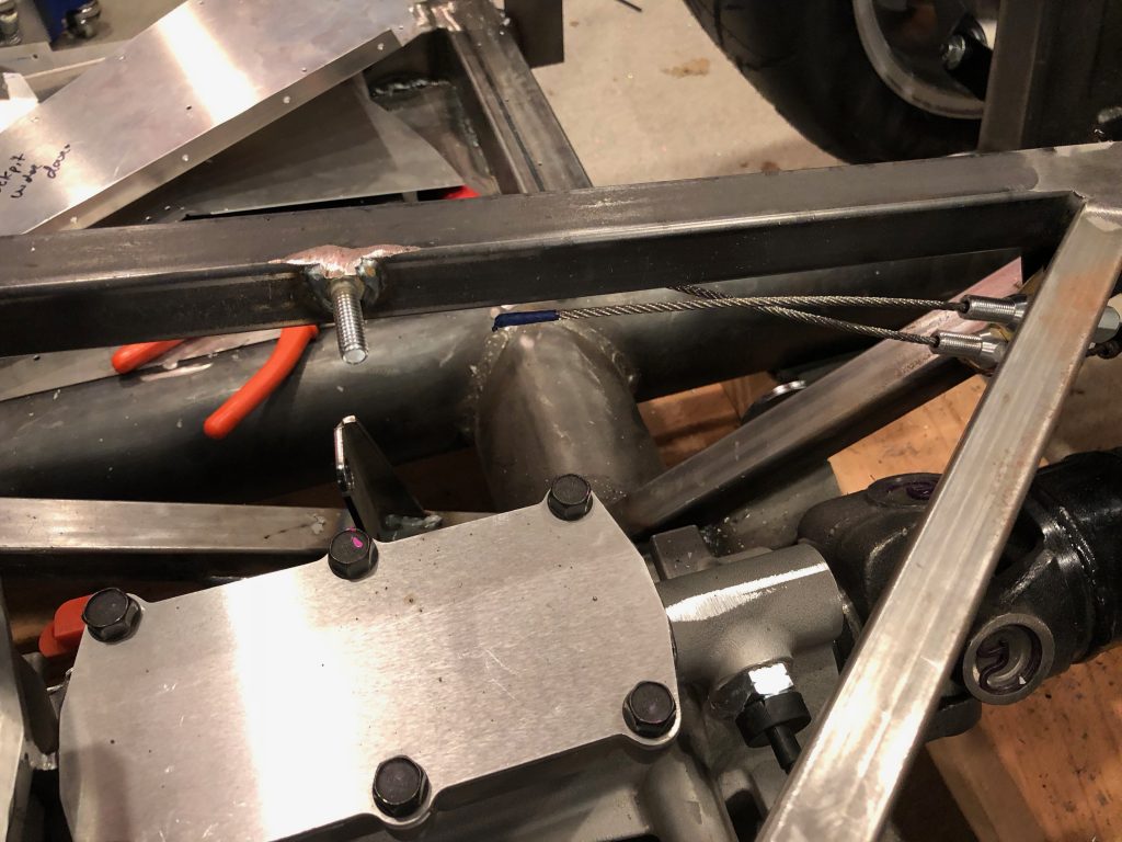
The adjustment mechanism will be bolted to the side of the tubing at the aft end of the transmission tunnel. Because of the angle of the tubing, only one of the two bolts will land on a piece of tubing, so I welded in a piece of thin plate steel.

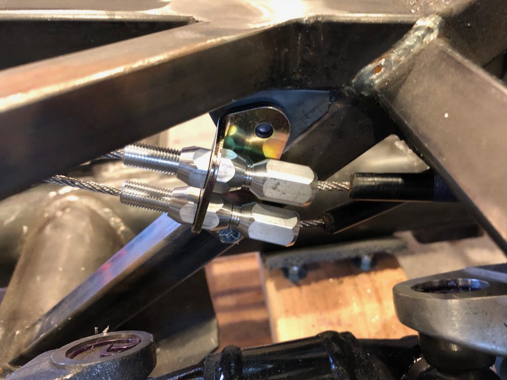
This is approximately the angle that the adjustment mechanism will sit at. I’ll drill and install a rivnut for the upper bolt once I determine the final angle of the adjustment mechanism.

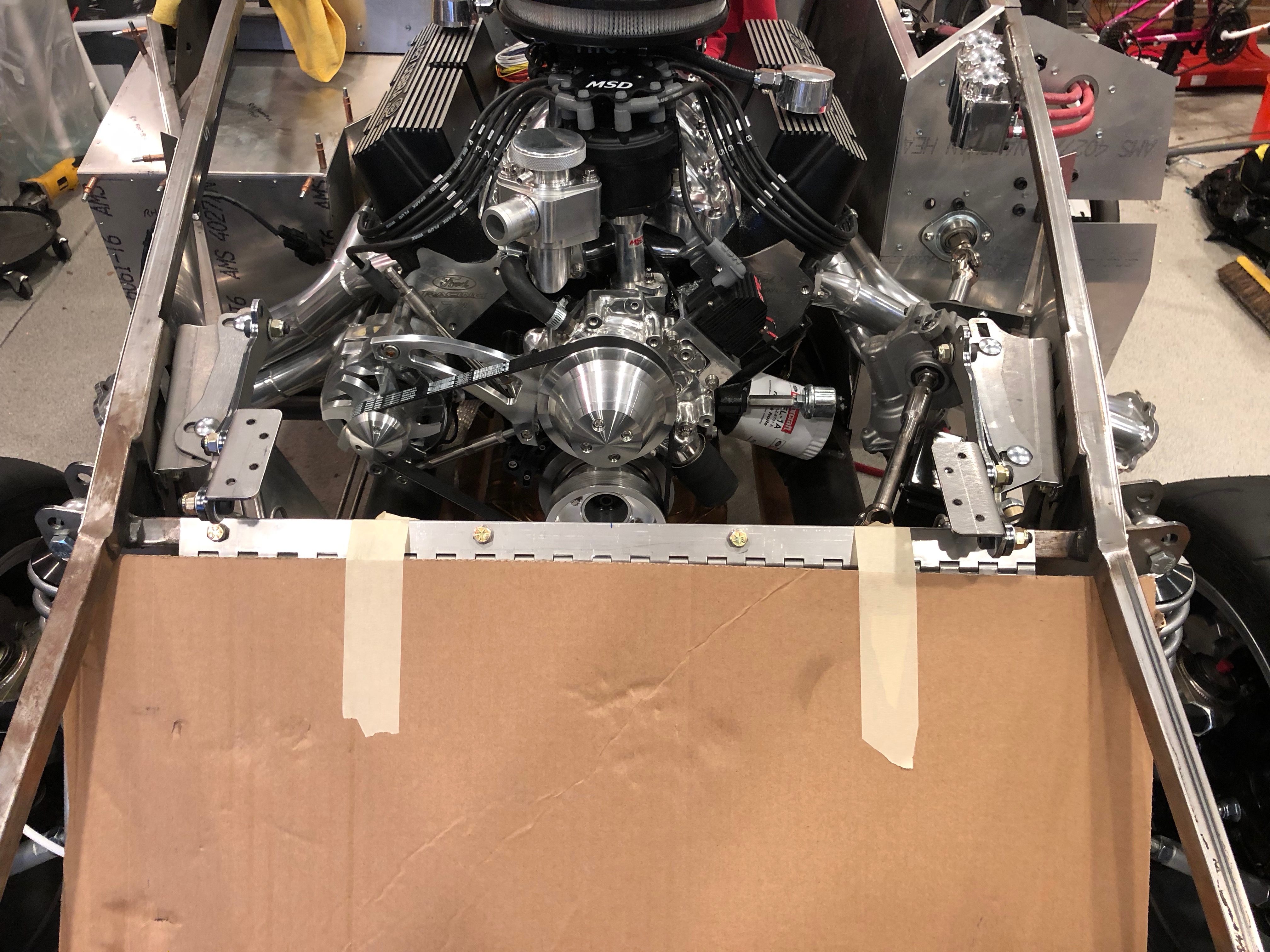
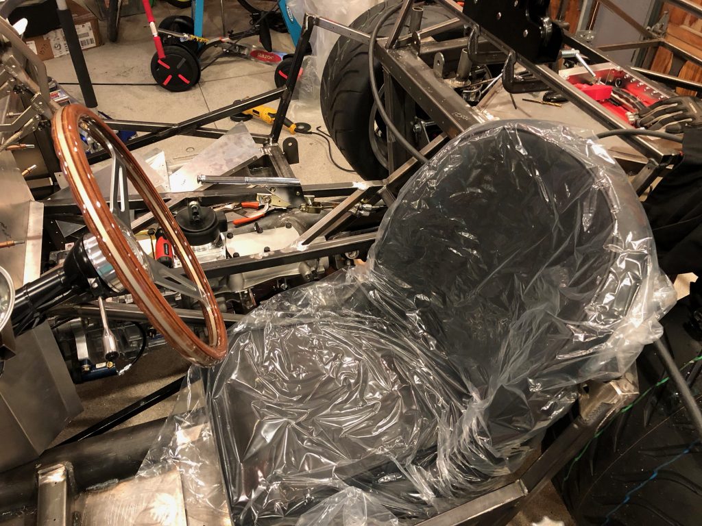
I temporarily clamped the parking brake in to see what kind of clearance I’d end up with between the gear shift and parking brake handle. This looks like it is going to work out well. The final check is to see how comfortable this is to pull when sitting in the car.

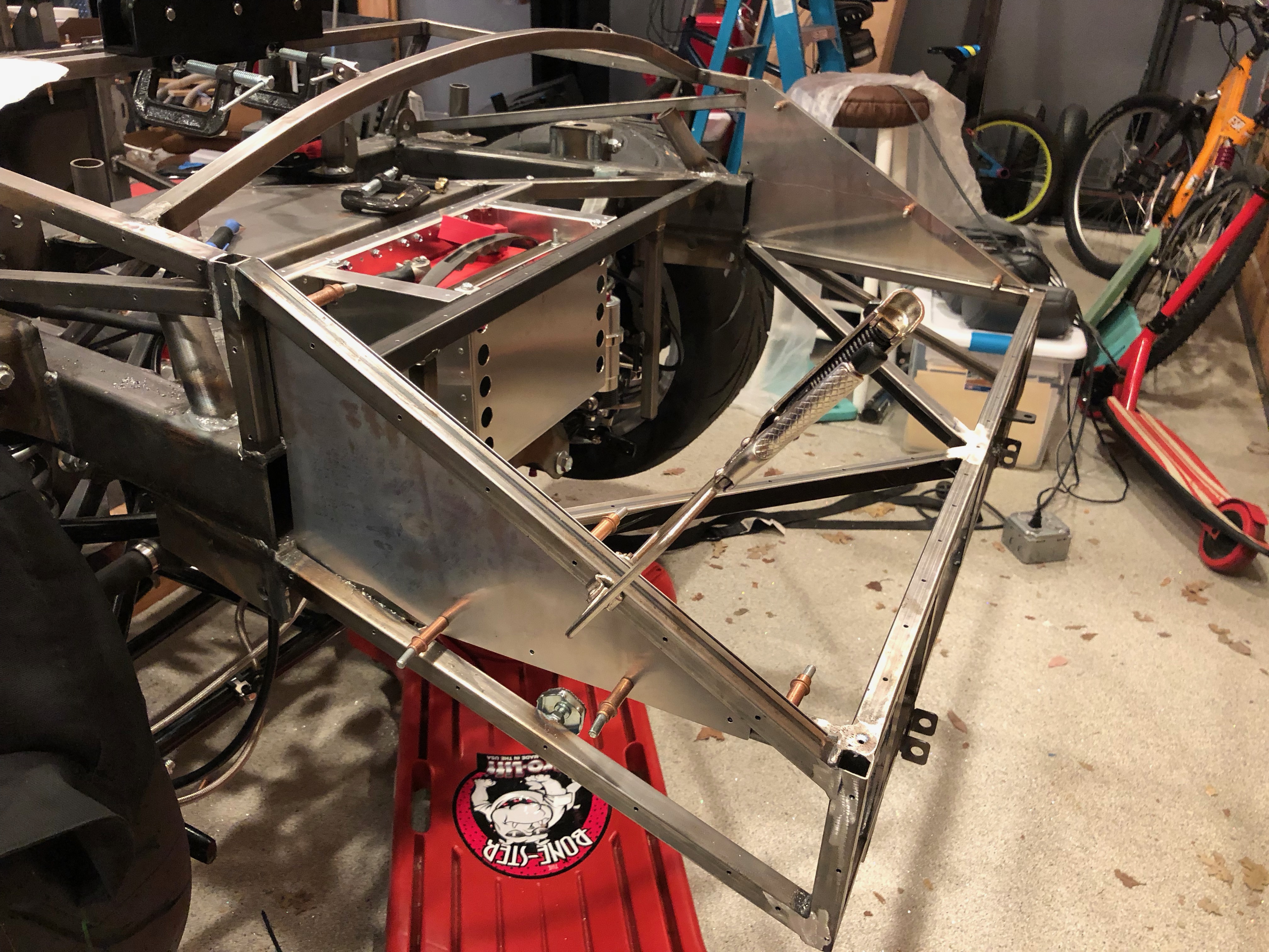
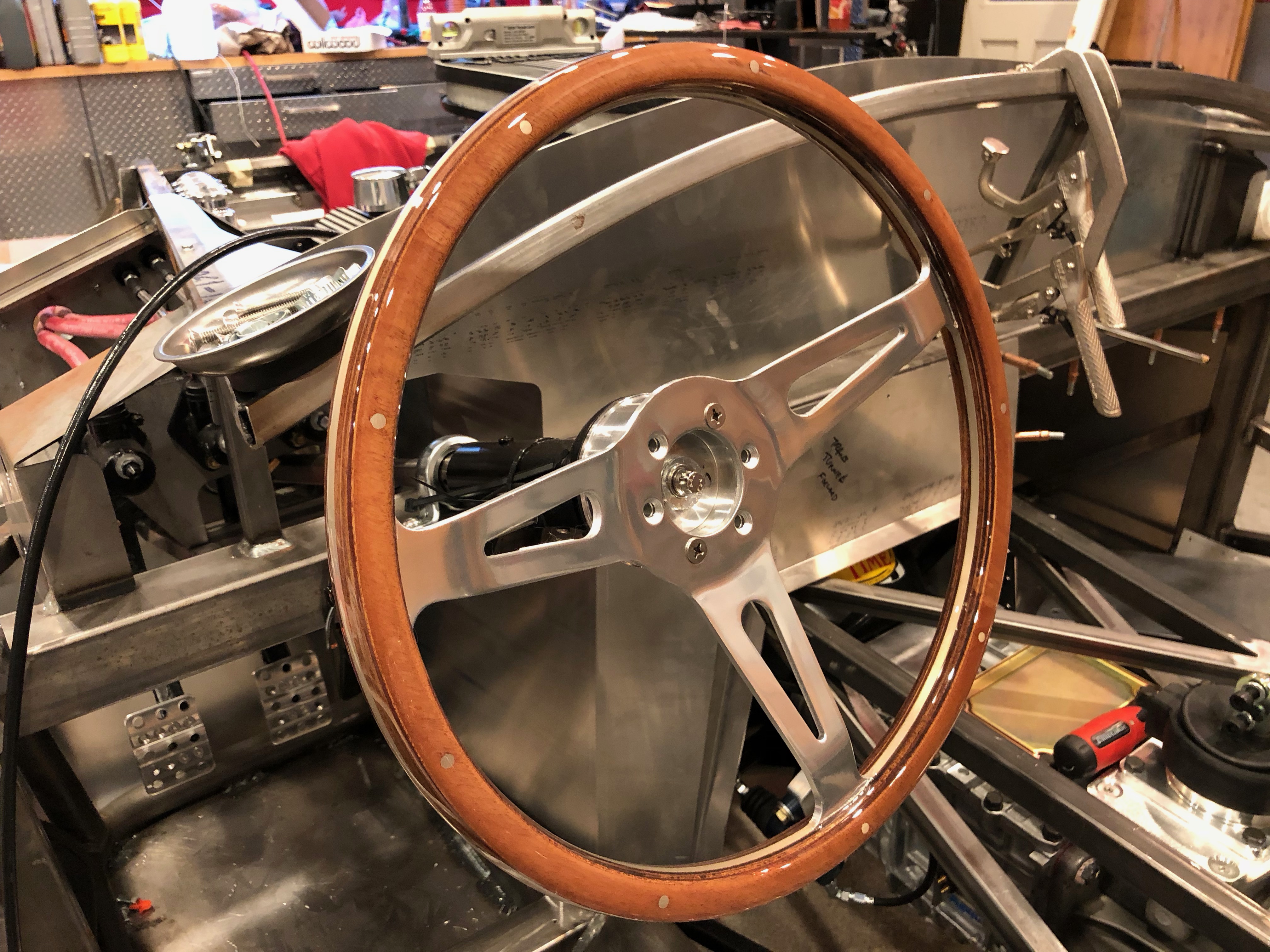
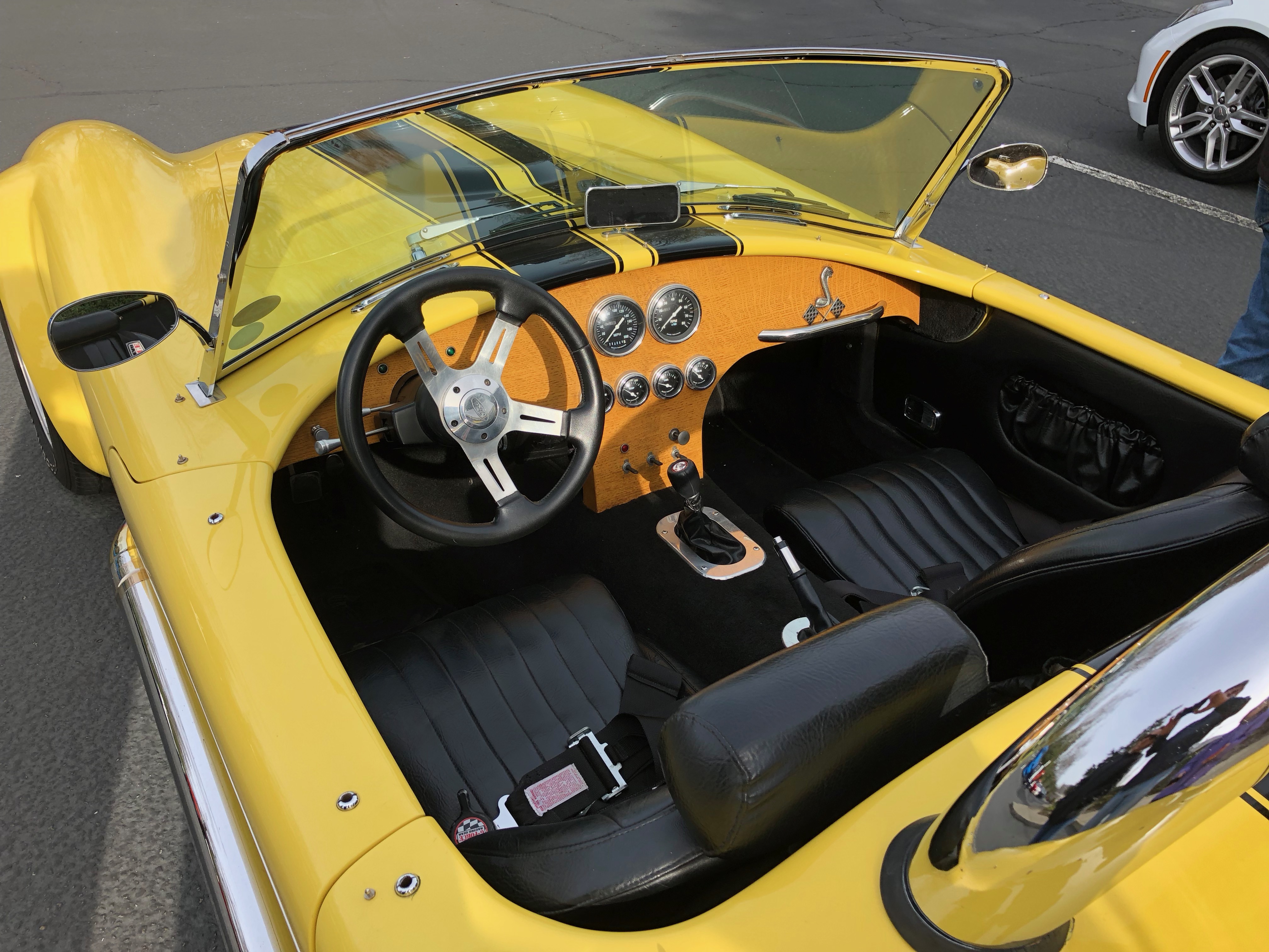
I temporarily installed the steering wheel while I was at it so that we could determine a comfortable seating position.

I sat one of the seats in the driver’s side of the cockpit and Jenn and I both got in to evaluate the position of the parking brake, gear shift lever, steering wheel and pedals. It looks like the parking brake location is going to work out great. Even with the mid-shift, we also determined that we want a gear shift lever that tilts forward slightly to put the shifter in a more natural position.One unfortunate discovery is that our plan for a dash that curves down to intersect the transmission tunnel won’t work because it will push my knee into the side of the steering wheel. It looks like we’re going to go back to the stock dash panel (though we’ll order a blank so that we can lay out the gauges where we want them.

One unfortunate discovery is that our plan for a dash that curves down to intersect the transmission tunnel won’t work because it will push my knee into the side of the steering wheel. It looks like we’re going to go back to the stock dash panel (though we’ll order a blank so that we can lay out the gauges where we want them.

Finally, we determined that the pedals need to move forward a bit. This is a fairly common tall-guy mod, so it shouldn’t introduce any problems.

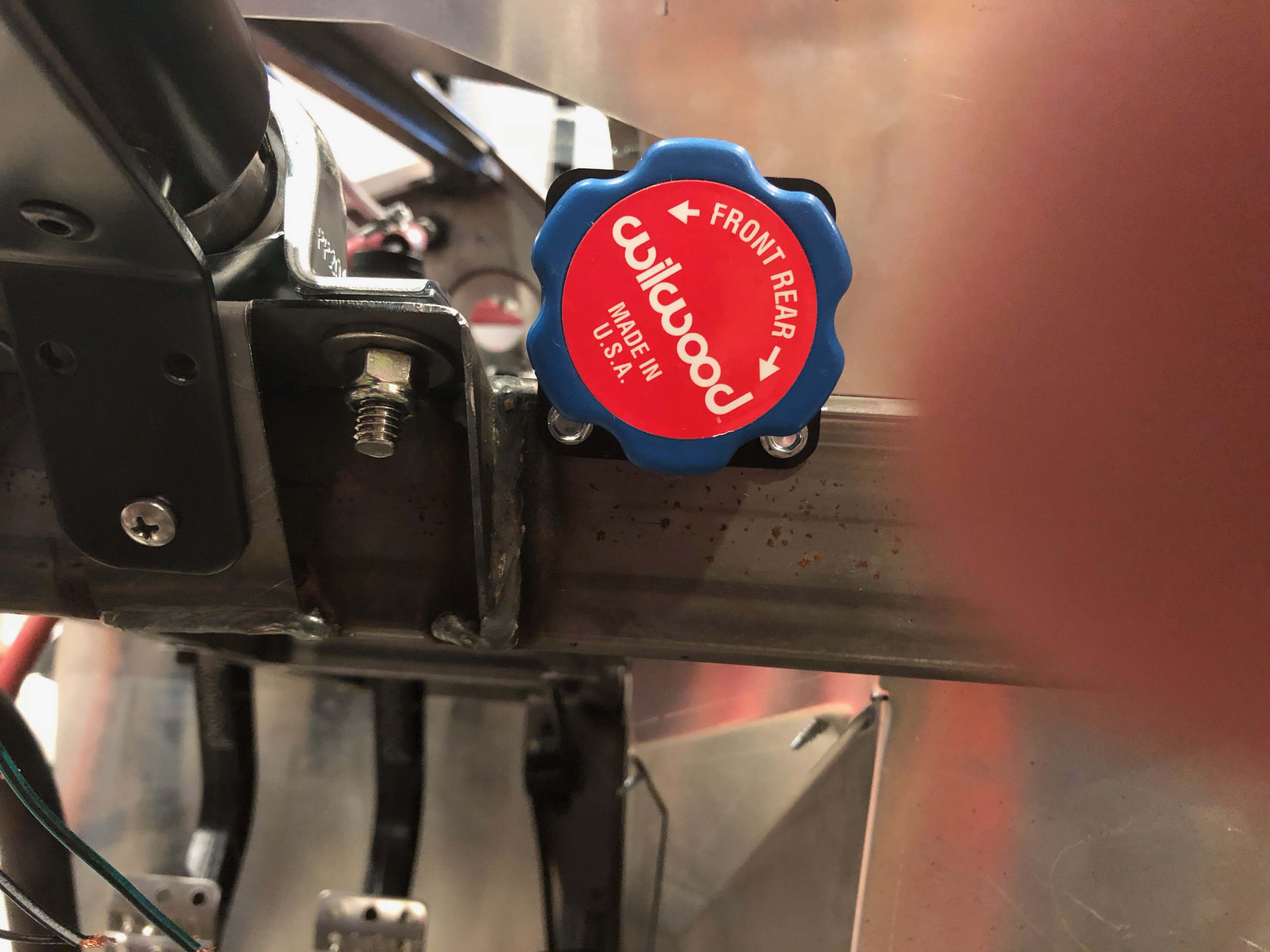
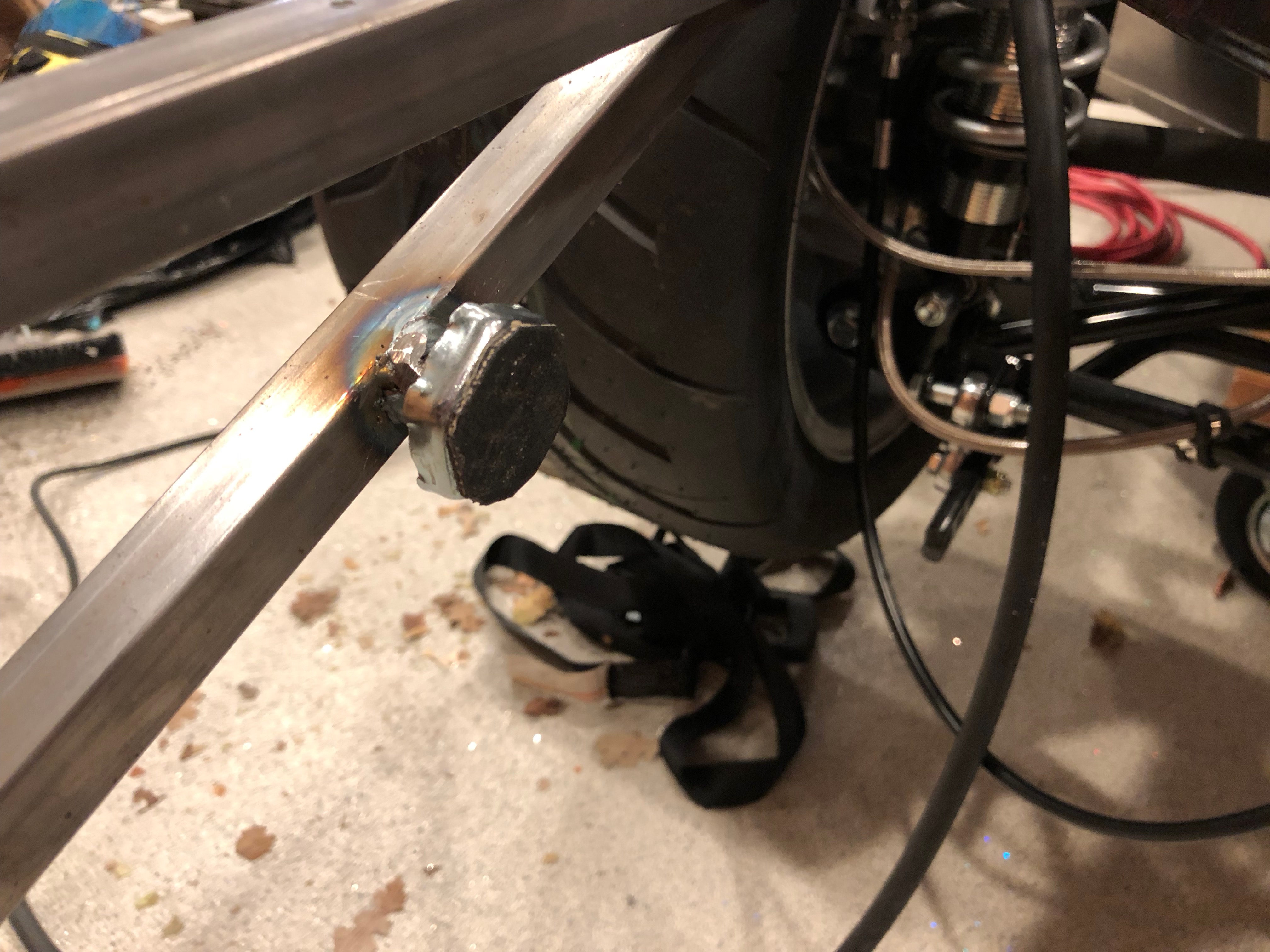
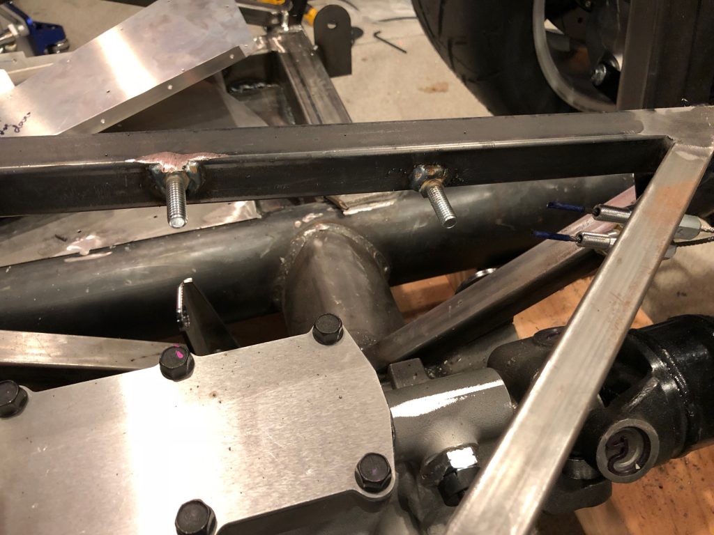
With the final location of the parking brake determined, I welded on the forward bolt.

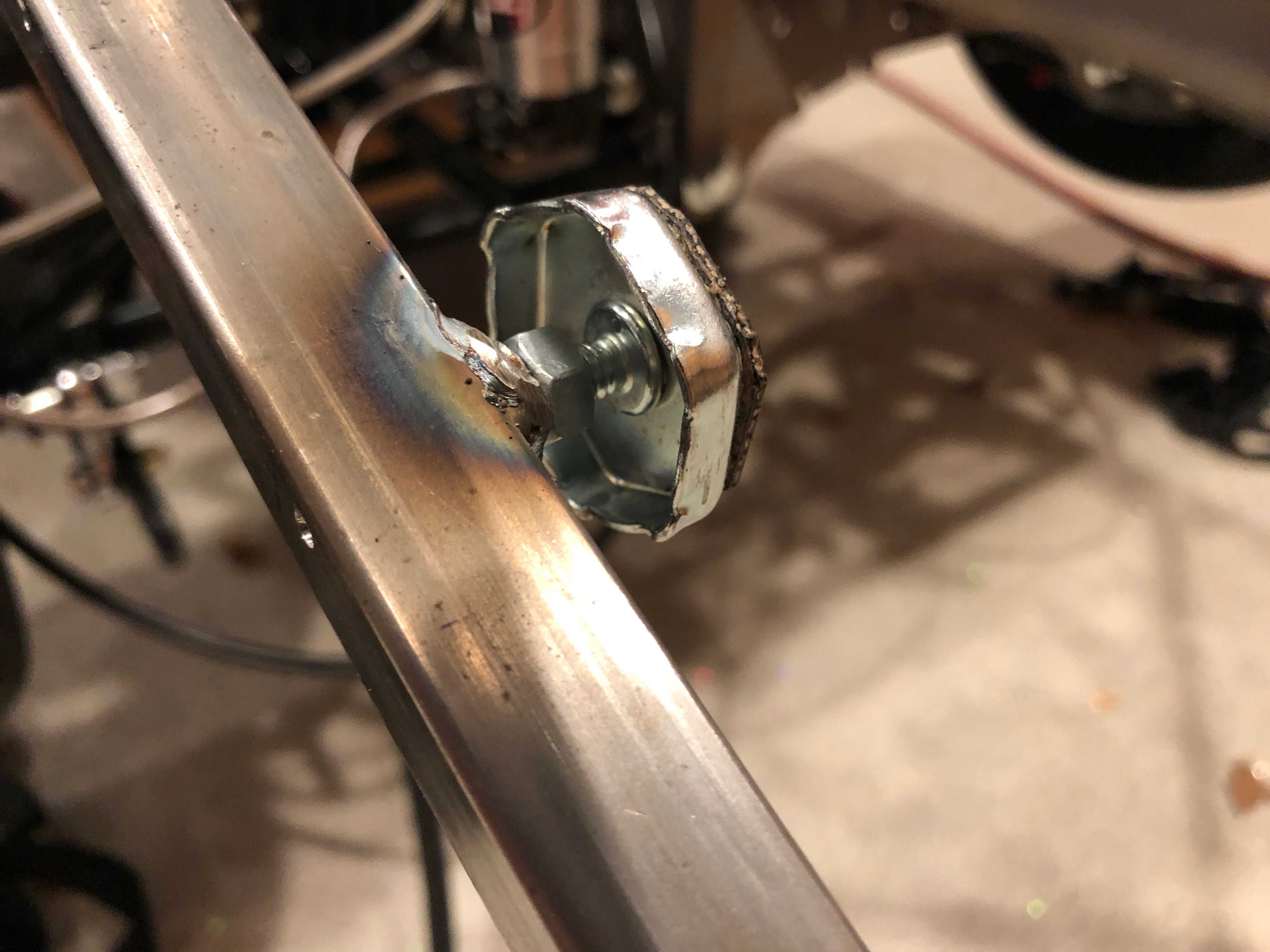
I then installed the parking brake and clamped the rear bolt in position before welding it as well.

I then bolted the parking brake in place so that I could make the final determination of how long to cut the parking brake cables and the angle of the adjustment bracket.

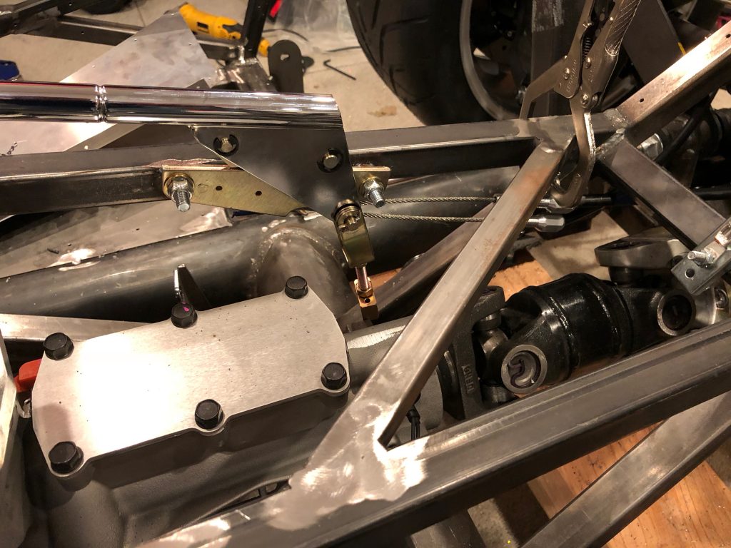
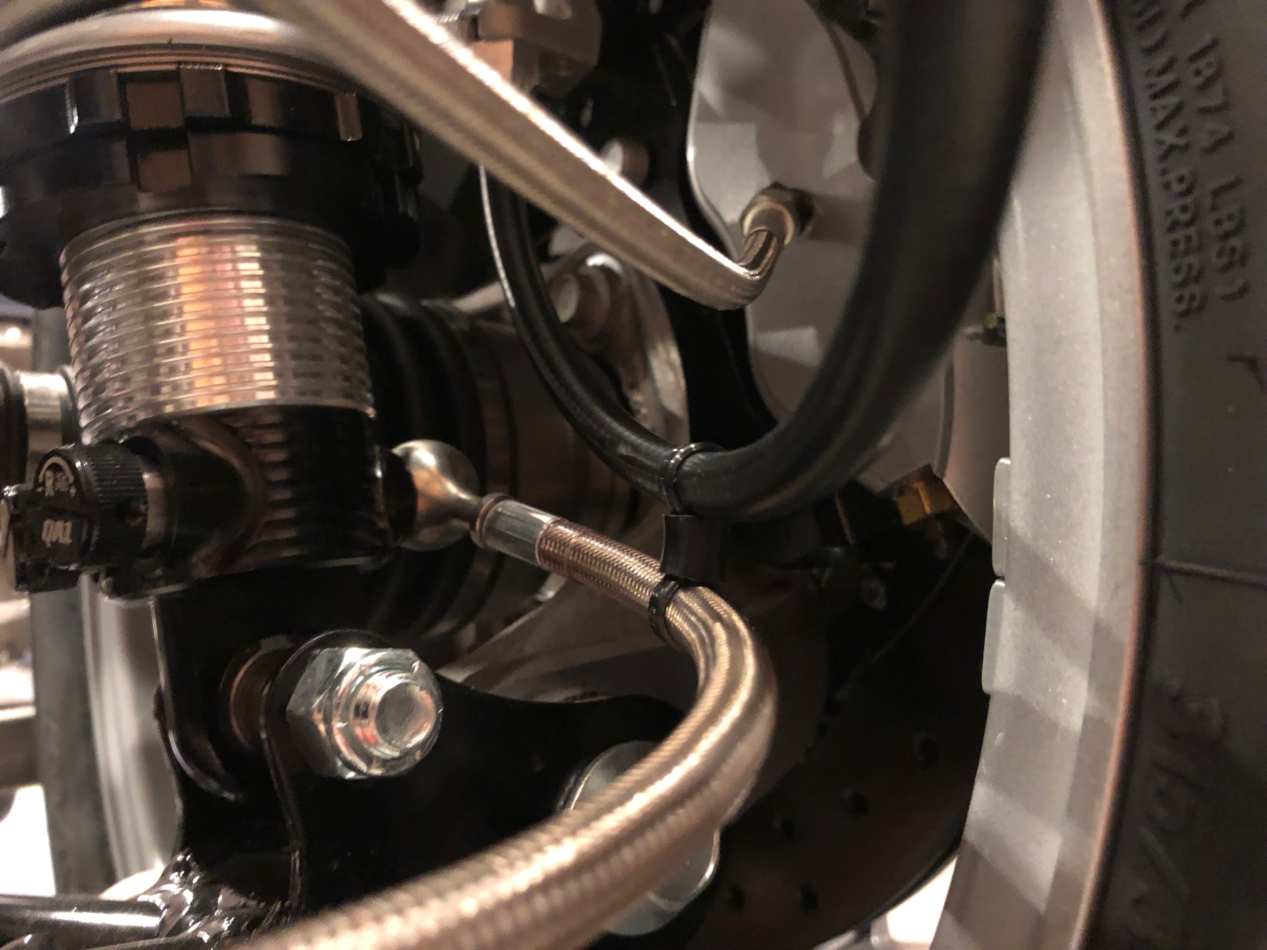
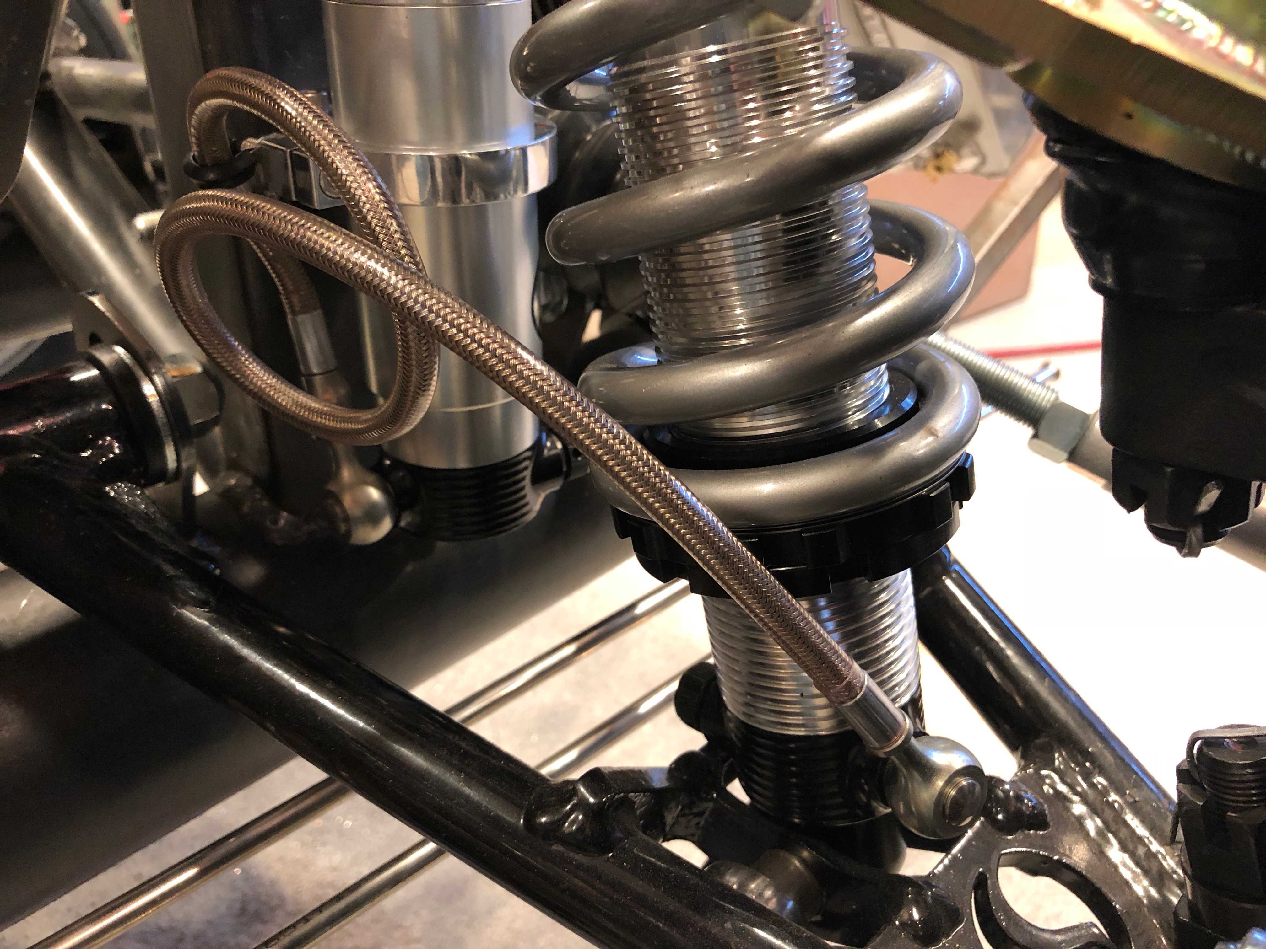
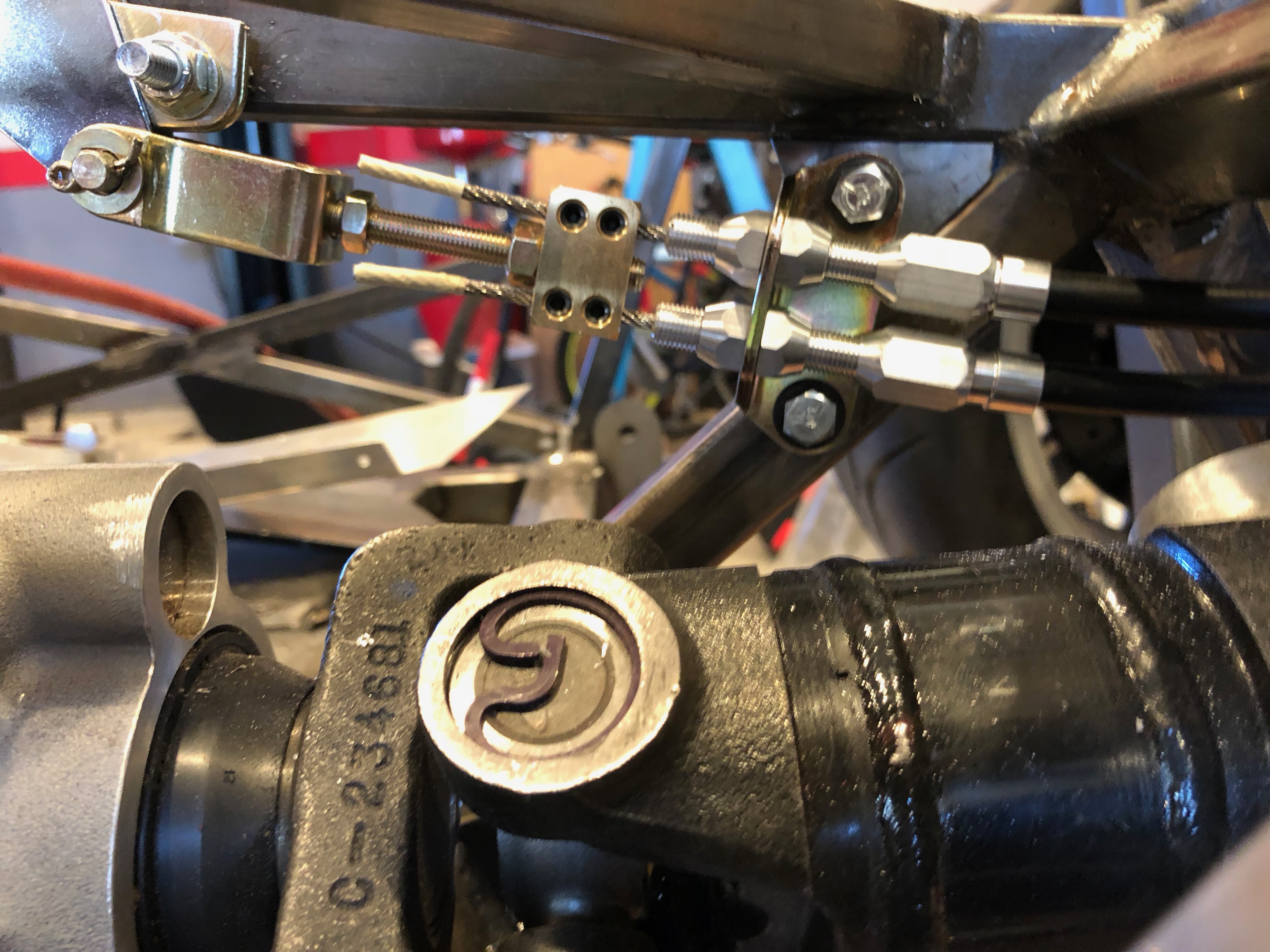
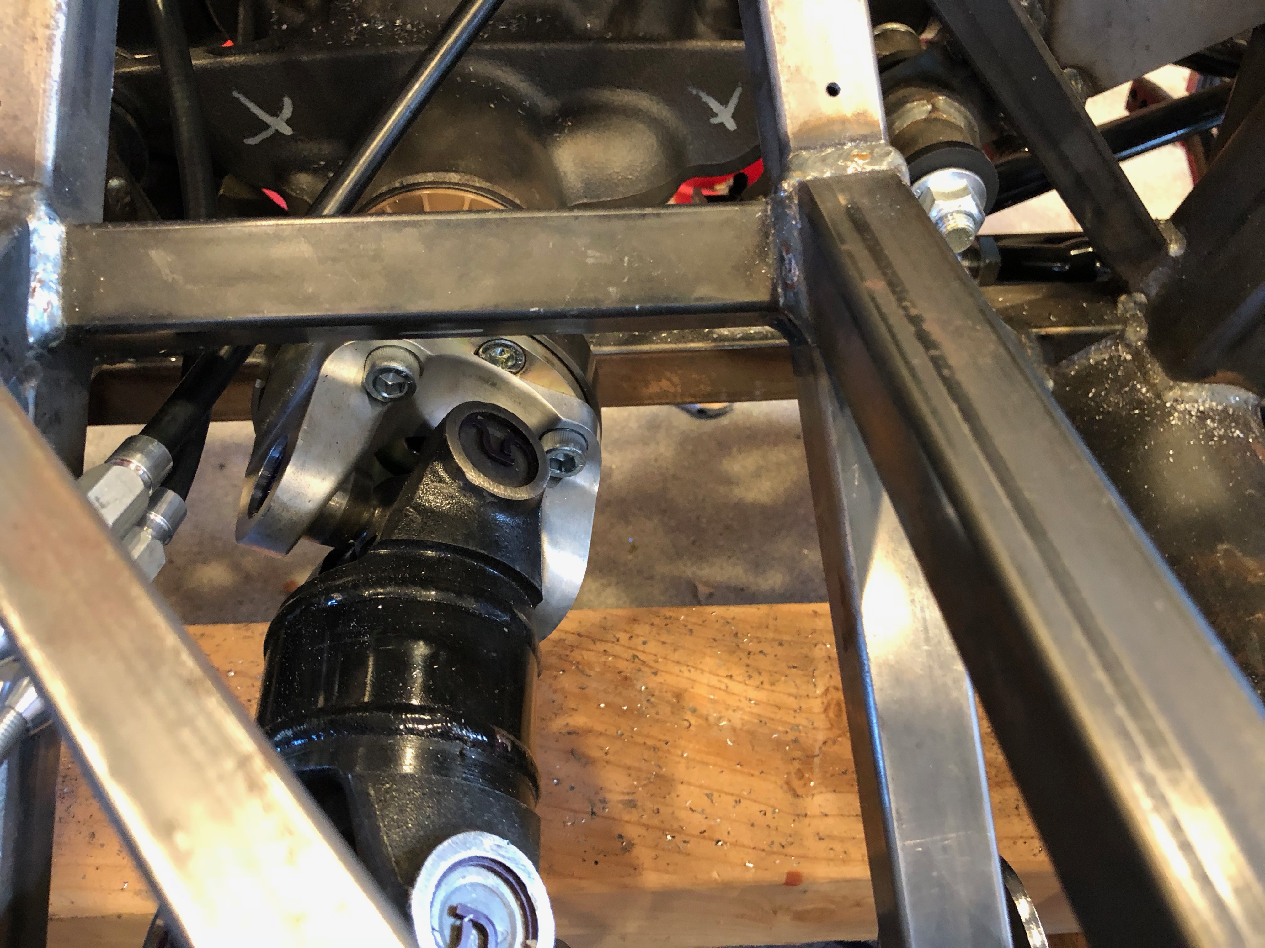
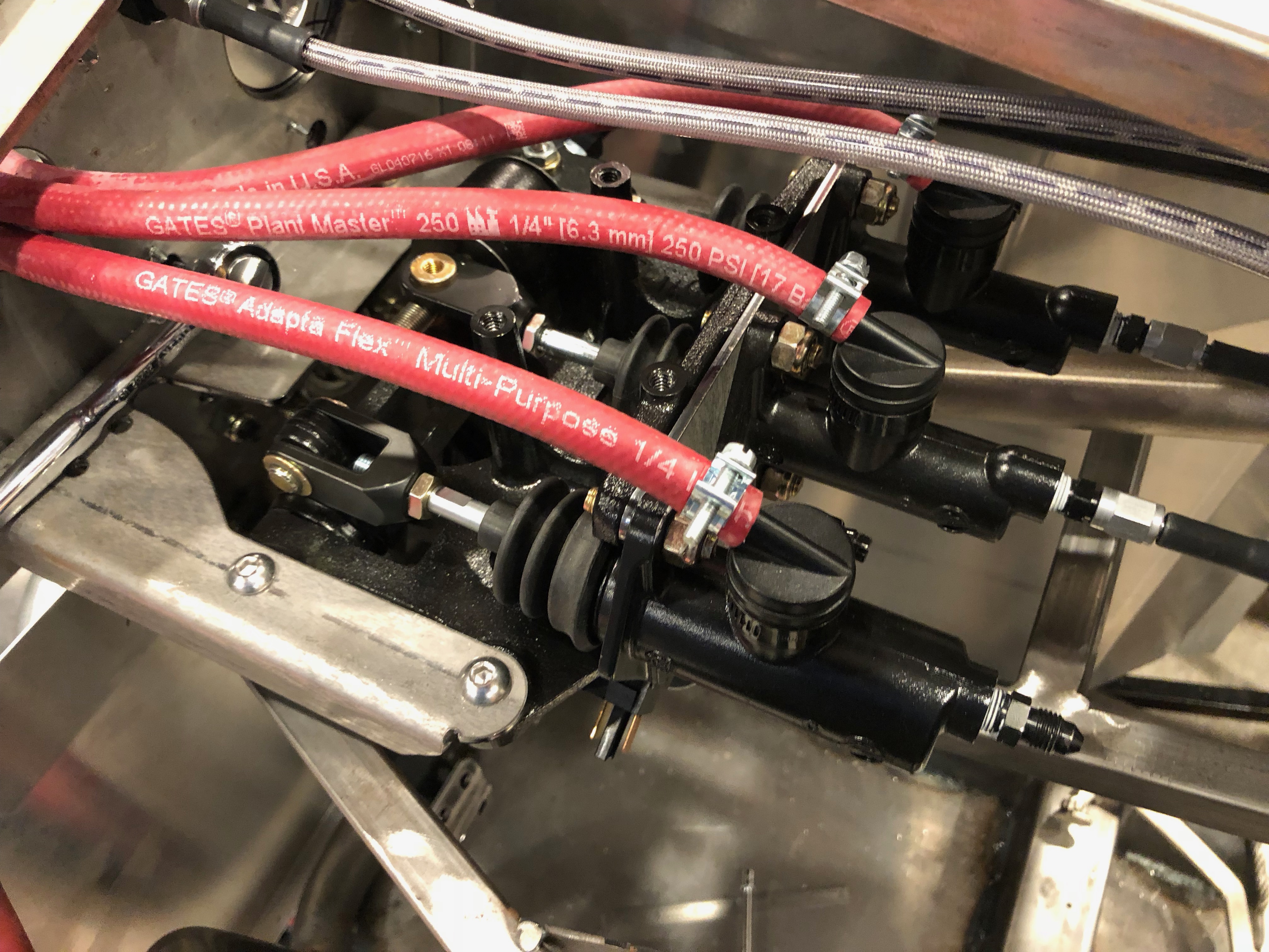
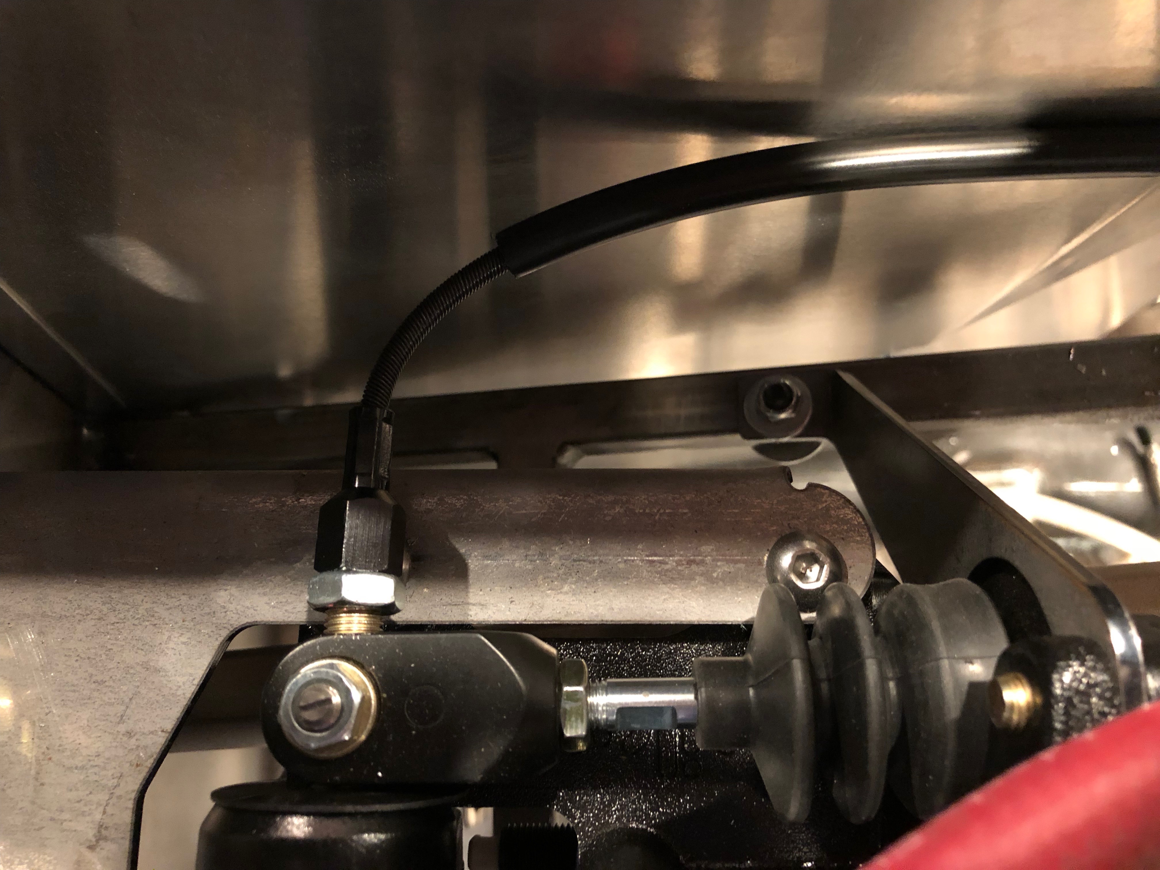
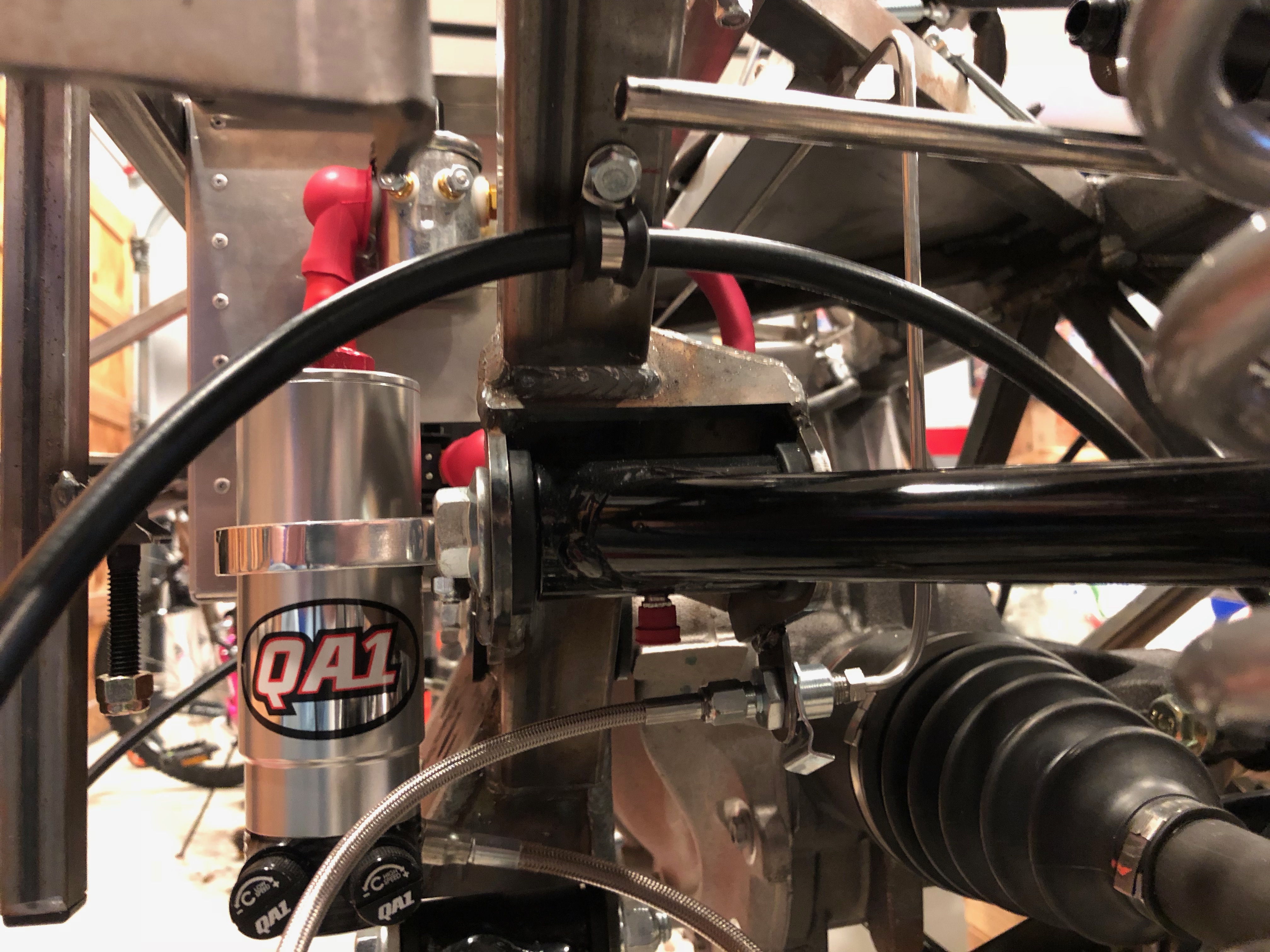
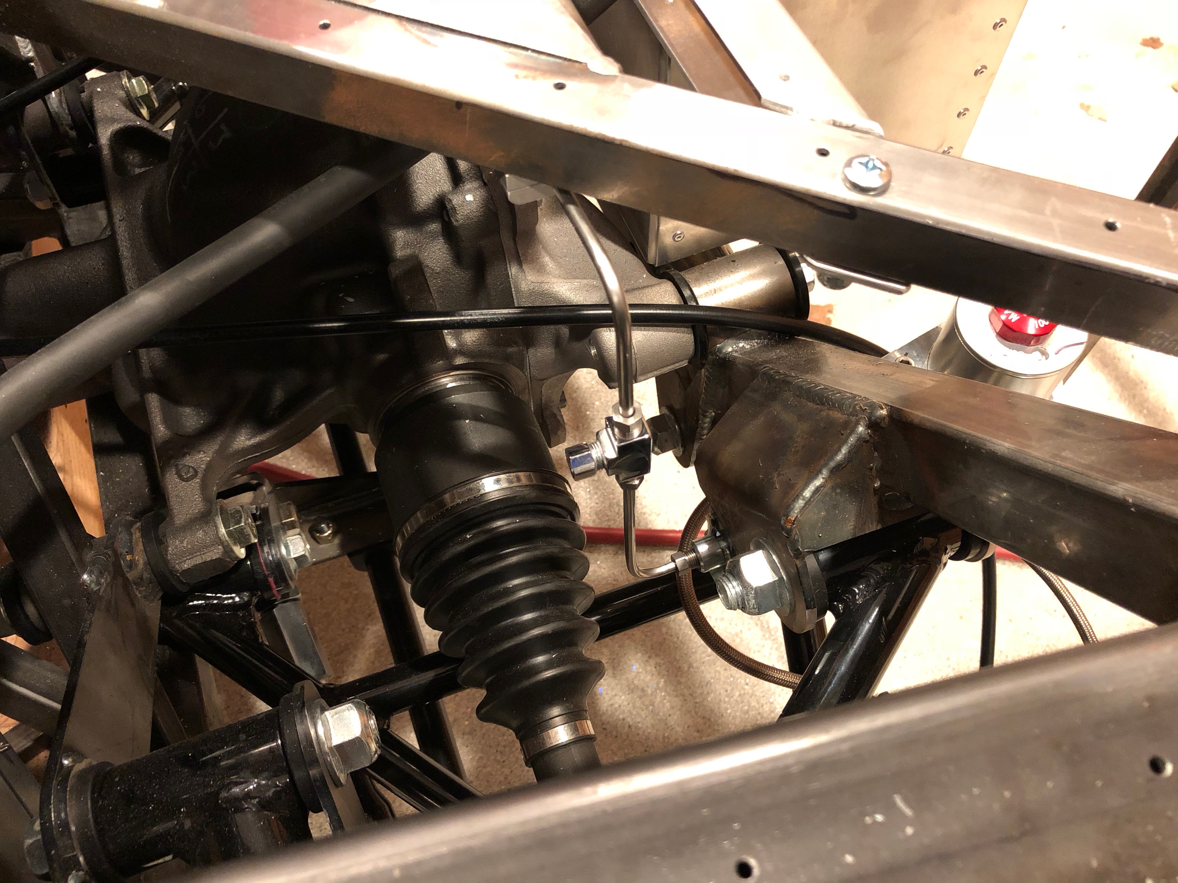
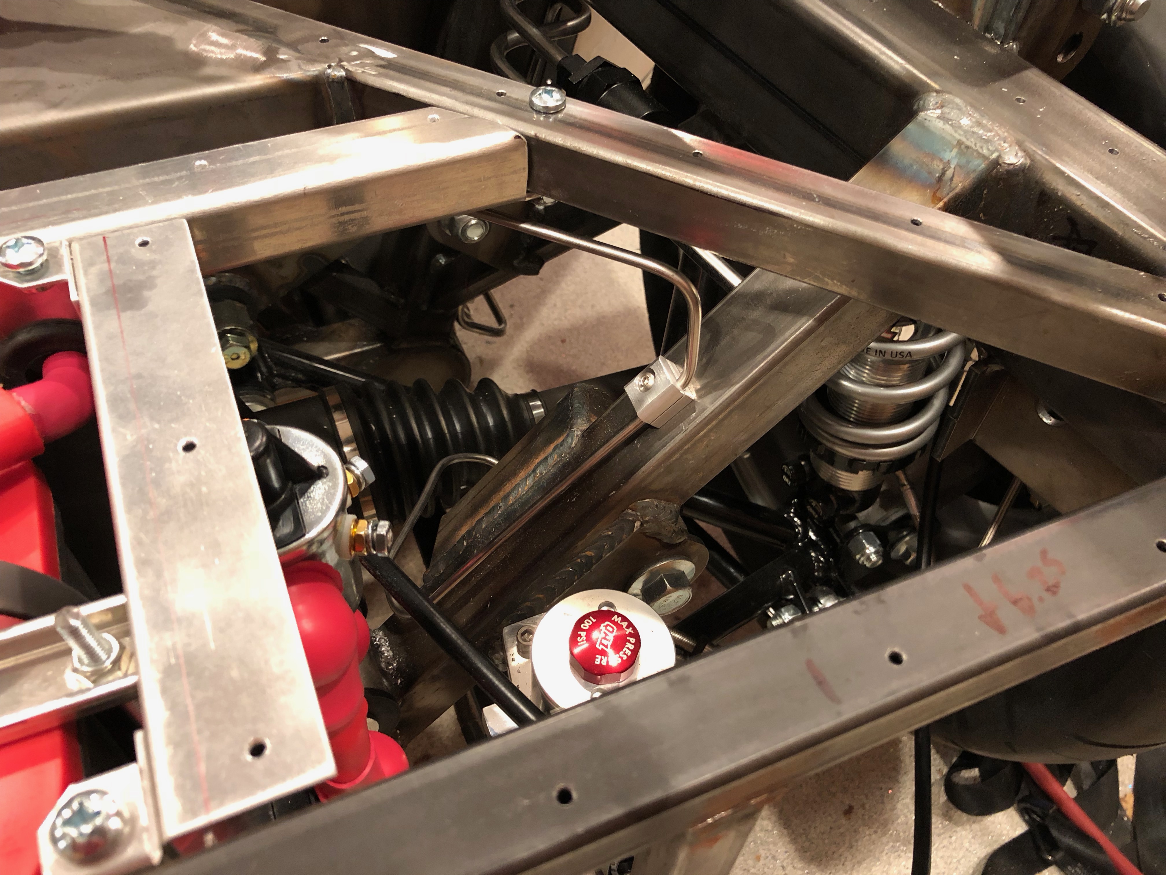
I re-routed the parking brake cable from the caliper.

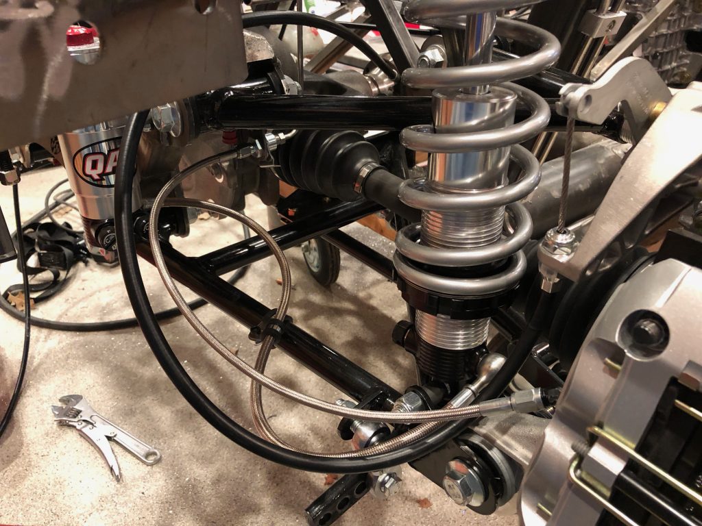
It now routes under the aft diagonal chassis member where I installed a 1/4-20 rivnut and an adel clamp.

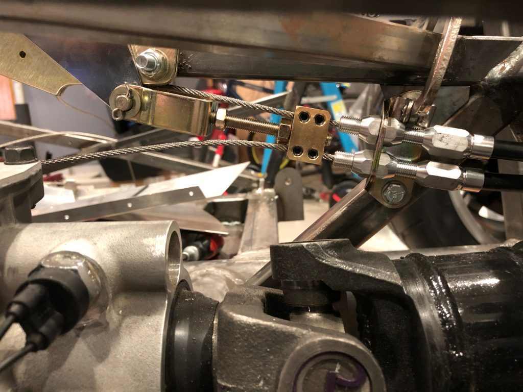
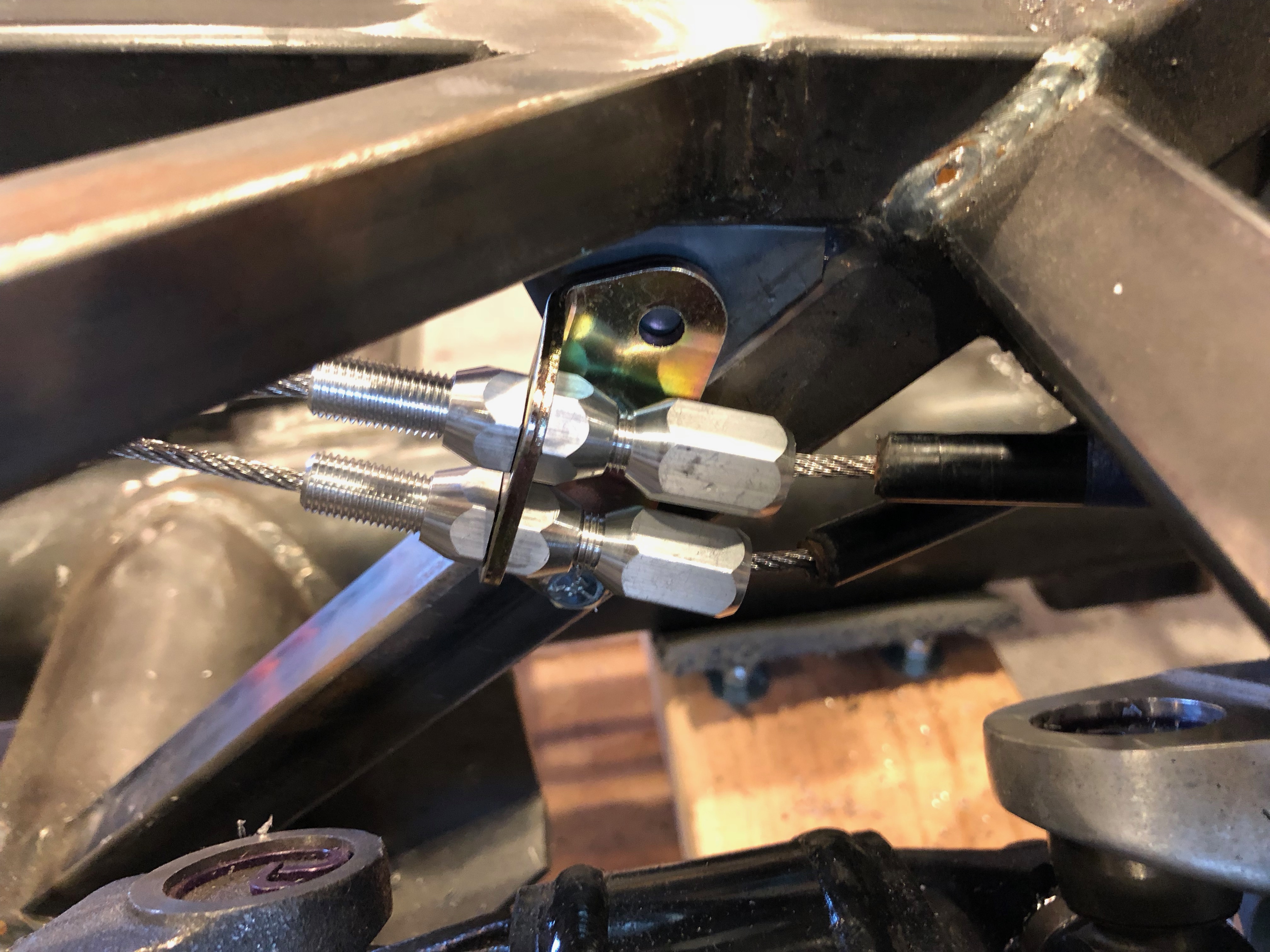
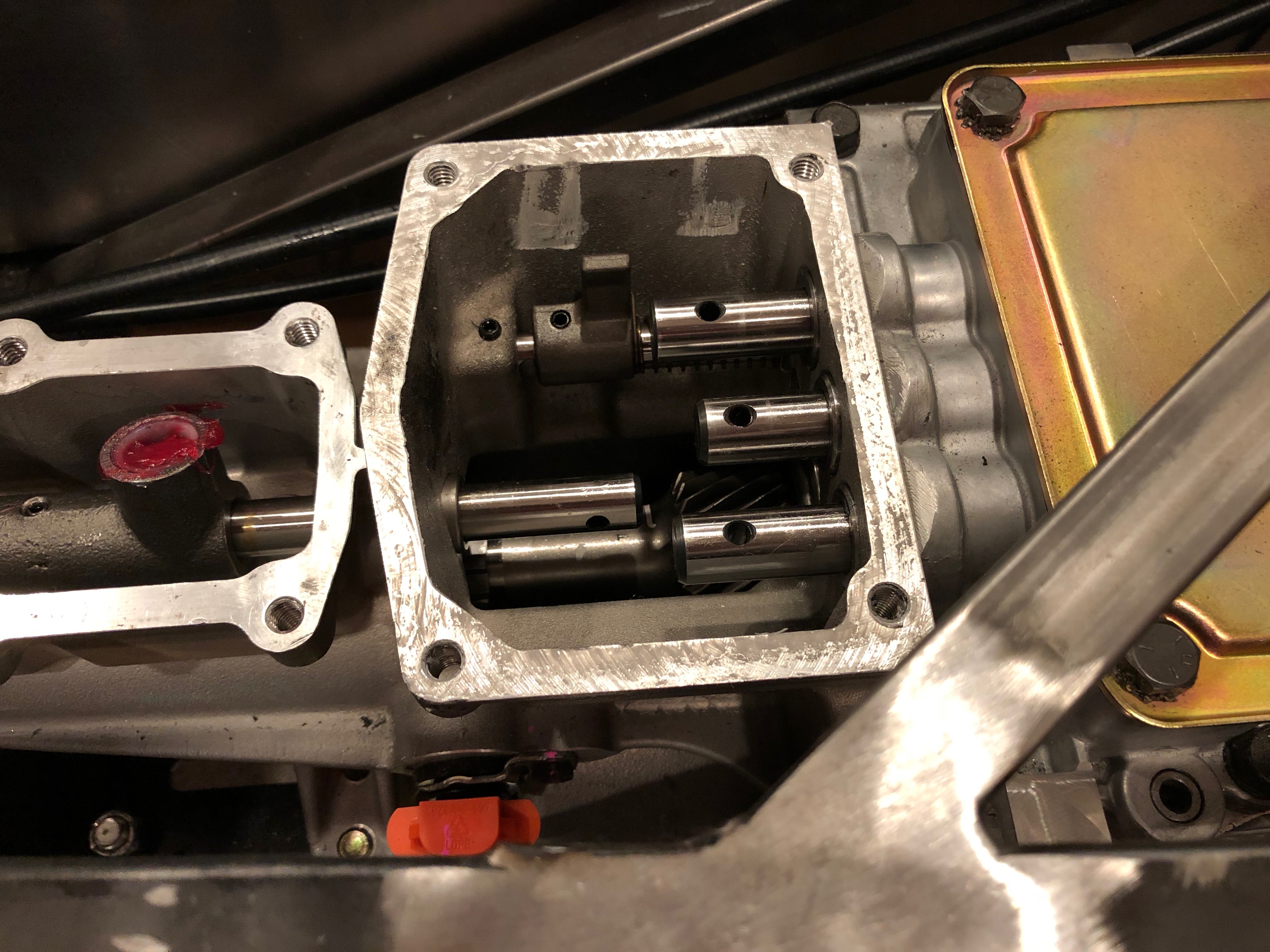
After trimming the cable sheaths to length, I ran the cables through the block and tightened down the set screws. I test the parking brake and it locks the wheel securly at about the halfway point in the pull. I have plenty of adjustment if the cable stretches over time.

Finished Installing Pro 5.0 Mid-Shift Kit

I stopped by Harbor Freight and picked up a set of punches. I bent the 3/16″ punch a bit until I could use it to drive out the roll pin in the forward lug of the aft shaft.

You can see that I started driving the pin out from the left side. This was a mistake as the pin hit the case before it could be driven out completely. This wedged the shaft so that it couldn’t be rotated or slid forward/backward. After scratching my head for a few minutes, I decided to try and bend the pin to make more room to drive it out. I hit the side of the pin with a punch and bent it enough to move the pin a little more.

After a few rounds of bending the pin and driving it further out, I managed to free the lug from the aft shaft.

Here’s how the pin was mangled in the process.

I put a rag back under the forward shafts in case I dropped a roll pin, and then began reinstalling the shift lugs. First up is the new center lug on the 3/4 shaft, this time installed upside down so that it can be driven from above.

I then reinstalled the outer lugs on the 1/2 shaft (bottom) and 5/R shaft (top).

I packed the intersection with moly grease.

I applied some black RTV to the flange and installed the cover over the aft cavity.

I then applied some black RTV on the flange of the forward cavity and installed the cover plate. Finally, I applied another thin layer of RTV and installed the shifter. All of the bolts were torqued to 20 lbf-ft.

The shifter came with a rubber cover to keep dust out of the mechanism. I’ll have to remove this (or at least pull if back) to adjust the mechanical stops, but I need to wait until I have a shift lever installed.

Started Installing Pro 5.0 Mid-Shift Kit

Jenn really wants to move the shifter forward and have a more vertical shift lever for a more traditional feel. We picked up the mid-shift kit from Mike Forte that includes a Pro 5.0 shifter and appropriate mounting plates and hardware. First up is to remove the bolts and forward cover plate. The RTV they used around the edge of the cover plate held it on tenaciously and was a pain to clean off of the flange after removing the cover plate.

The instructions from Tremec have you knock out the roll pins holding the three shift lugs and just let them fall to the bottom of the aft case. It’s pretty trivial to fish a rag under the lugs to catch the roll pins though.

After removing all three roll pins, the lugs can be slid off the shafts pretty easily.

Here are the three lugs. The kit from Mike includes a replacement center lug, but it looks identical to the one I removed.

The new center lug is installed upside down so that the opening is facing up, but it can’t be installed until the forward lug on the aft shaft is remove (the one on the right in the picture). Without removing the shaft, it’s a bit of a pain to remove the lug because you can’t get a punch directly aligned with the roll pin. I managed to drive it part way out, but I’ll need to fabricate a slightly angled punch to drive it the rest of the way out.

The reason that Tremec doesn’t care if the roll pins fall to the bottom of the case is that they want you to separate the front and back cases to entirely remove this aft shaft, and it’s pretty easy to retrieve the roll pins if the aft case is removed. That’s not strictly necessary though; once the forward lug is removed, the aft shaft can just float and won’t interfere with the shift lugs. The weight penalty is negligible, and it’s way less work to leave the case halves mated.

Cobra Experience Museum

I took Jenn and the kids to the Cobra Experience museum in Martinez, CA this morning. They had a “Cars & Coffee” event in the morning with a bunch of custom cars including 4-5 Cobras. We’re considering something similar to this for our dash, so I grabbed a picture.

All of the cars in the Cobra Experience museum are genuine Shelby Cobras. This is an early 289 slab side Cobra; Jenn really likes the grill on this car.

Another 289 I believe.

These are both 427 Cobras.

Virtually every kit Cobra I’ve seen has polished side grills, but every single Shelby Cobra in the museum had painted grills. Jenn likes the looks of these better, so we’re going to paint ours.

I thought this was amusing. 🙂

Coolant System Work

I received an order from Summit Racing with my new coolant overflow tank. Given the volume of coolant in the engine, the consensus on the forums is that the coolant reservoir tank that comes with the kit is too small. This tank from Canton Racing is over twice the volume at 2 qts. It’s also a beautiful piece of work.

I have been thinking about mounting the reservoir inside the right F-panel. This should clear the upper radiator tube, but I’m concerned that it will interfere with the hood hinge and support strut.

To see whether that is true, I assembled the hood hinges.

These attach to the brackets welded to the chassis just behind the upper radiator support.

I installed one of the support struts to get a sense of how far back it extends (though it will obviously be compressed when the hood is down). From what I can tell, the aft end of the strut will be roughly level with the upper square tubing.

I might be able to install the reservoir inside the right F-panel underneath the support strut, but I’m concerned that the strut will push the reservoir too low. Another option is to mount it behind the radiator. I should be able to get it high enough here, but I’ll have to fabricate a rather complex mounting bracket.

Now that I know that the upper radiator tube will clear the reservoir in either mounting position, I decided to go ahead and install it.

The tube was slightly too long to fit and there is a slight bend at each end. I cut a bevel to create a small gap at the aft end.

The forward end also needed a slight bevel to create the necessary gap between the tubing and the radiator.

Finally, I installed the upper tube in place and secured the clamps.

I used some T-bolt clamps to secure the rubber connecting hoses in place. These are so much better than the worm clamps that I was using.

Here’s a shot of the whole vehicle. When you look at it like this, it doesn’t look like there has been much progress in the last few months, but there are a lot of details that are lost at this scale.

Rear Brake Line

After I boogered up the rear brake line last night, I decided to reroute it to simplify the necessary bends. When I first fabricated the rear brake line, I hadn’t installed the battery box, so I wanted to keep it tight to the other tubing. Now that I know where everything sits, I realized that it wasn’t necessary to have such a complex routing. The new routing has the brake line turn straight up from the fitting on the right side. It’s hard to tell from this picture, but the line is completely behind the inner CV boot. Even at full compression travel, I don’t think the inner CV boot could ever flex as high as the brake line, but I wanted some lateral clearance as well.

I installed a couple of rivnuts on the angled square tubing to secure the brake tubing where it crosses the chassis.

The second brake line clamp is on the left diagonal square tubing.

I put the tee in the vertical leg on the left side. I haven’t figured out which direction I’m going to have the third leg go from here, but it won’t interfere with any part of the suspension or drivetrain regardless of the direction.

Trunk Aluminum, Fuel Tank Stabilizers and Rear Brakes

Before I can install the fuel tank for good, I also needed to wrap up the trunk aluminum. I had previously drilled the upper trunk floor, but I never did the same for the lower trunk floor. I started by removing the tank (hopefully for the last time before the final reassembly). I needed to do this so that I could mark the chassis tubes on the underside of this sheet. After laying out all of the holes, I drilled the sheet to the chassis tubes. You can also see that there is a row of rivet holes tying the upper trunk floor to the lower trunk floor.

With the lower trunk floor in place, I cut and bent a piece of scrap aluminum to make the access panel cover for the fuel sender and fuel return and vent fittings.

I drilled this to the floor with a #30 bit for now. I’ll open these up for the right size screw before installing nutplates.

I also cut out and drilled an access panel cover for the fuel pump and supply fittings.

The fuel tank is narrower than the cavity in the chassis that it fits within, but I don’t want the fuel tank to be able to slide from side to side. To prevent this, I drilled a 1/4″ hole in the lower diagonal tube on the inside face and welded on a 1/4-20 nut.

I threaded a leveling foot with threaded stud into the nut. I had previously bonded a piece of the same reinforced rubber sheeting onto the foot where it will contact the tank.

You can see on the other side that there is a run nut threaded onto the shaft as well. Once the tank is installed, I can tighten the foot against the tank and lock it into position with the jam nut.

Before reinstalling the tank, I wanted to wrap up the rear brakes. I started by adding a brake line clamp on the right diagonal tubing. Unfortunately, when I was trying to wrap up the other end of this piece of tubing, I botched the flare. I don’t think the tubing is salvageable, so I’ll probably have to fabricate a new piece.