Added Rivnuts to F-Panels

The f-panels have flanges on the rear edge that will attach to the panels that close off the rear of the front wheel wells. Most people rivet these panels on, but apparently they interfere with getting the body on and off, so some people recommend making them removable. I drilled a series of holes and added rivnuts to them so that I will be able to attach the panels with screws.

I also added a couple of rivnuts to the inside of the left f-panel to attach the control box for the electric power steering. You can also see a rivnut in the chassis that will be the grounding point for the electric power steering system.

Welded New Chassis Tube

I clamped a piece of 3/4″ tubing to the outside of the forward tube and welded it in place. It was then fairly easy to flex the two pieces of tubing into alignment and weld the rear pieces together. I’ll finish going all the way around the weld and clean it up with a grinder when the car comes back apart.

Taillight Wiring and Clutch Pedal Clearance

I installed Weather Pack connectors on several of the tail lights. I ran out of three-conductor connectors though, so I couldn’t finish all of them.

I also installed the female connectors on the chassis on both sides. These are electrically identical and all lights have identical connectors. This is possible because the InfinityBox lets you use the same lights for brakes and turn signals. Although this is possible with a combination of relays in a traditional wiring harness, most builders don’t wire it this way. They end up using the dim filaments in all four tail lights for their parking lights, but the bright filaments in one pair of lights for the brakes and in the other pair of lights for the turn signals. In our car, all four bright filaments will be used for brakes and turn signals.

When I moved the pedal box up, it caused interference with the 3/4″ tubing that cuts through the middle part of the driver footbox. There must have been some stress in this tubing because the two pieces shifted out of alignment with each other when cut apart. I’ll weld in a new piece of 3/4″ tubing on the outside of this tubing. I’ll try and realign the pieces of tubing when welding.

It took a few extra trims on the forward end of the tubing to allow the pedal to go all the way to the front of the footbox, but I now have full clutch travel.

Horn and Taillight Wiring

I cut back the sleeving on the wiring harness to the front right of the car and put a terminating piece of heat shrink on it to keep it from unraveling. I then cut the horn wire and created a jumper between the horns.

I also installed a grounding point on the forward 3/4″ tubing and grounded the horn there. The lights and fan will also ground here.

The ground wire also jumpers between the two horns.

I also added a grounding point on the left side diagonal chassis member to ground the rear load cell.

I figured out which wires will be routed to the rear lights and put some expandable sleeving over them. I’m routing them over the top of the fuel tank.

I used a solder sleeve to tee the parking light wire and then dropped the wires down behind the tank near the center.

Wiring Harness and Horns

I slipped some expandable sleeving over the bundle of wires going to the front of the car and secured the harness to the firewall to the left of the load cell.

The harness routes under the upper chassis tube and is secured to the outside.

The harness will split at the top of the radiator and route to the various loads at the front of the car: lights, fan, and horn. I went ahead and installed the horns along the upper tubing beside the radiator.

Spliced Into Front Load Wires

I used some solder sleeves to splice the fusible links into the six wires on the front load cell that need to be indicated on the dash.

I put an extra piece of heat shrink over the solder sleeve to protect them.

I also added a rivnut to the side chassis tubing to  ground the front load cell.

Accelerator Pedal

The accelerator pedal was much too close to the brake pedal, so I reversed the arms on the pivot shaft (the pedal arm was to the left of the upper arm). By reversing these, the pedal moves about 1″ to the right. This made the upper arm interfere with the steering shaft, so I put a 15-20º bend in the upper arm to put the upper end in about the same position it was when it was mounted on the other side.

I installed a couple of 1/4-2o rivnuts in the mounting plate so that I didn’t have to try and install a nut on the back side. You can see how much farther the gas pedal is to the right of the brake pedal. It was pretty each to accidentally press the brake pedal and accelerator pedal at the same time before, but now it’s pretty hard. I’m really happy with the pedal spacing now, but it does present another problem. With my foot naturally laying across the accelerator pedal, my shoe goes 2-3″ to the right of the pedal which is well under the left exhaust header.The inner footbox panel on the driver’s side doesn’t have enough room, so I’m going to need to fabricate a new one with a bump out for my shoe.

Pulled Lifters, Raised Pedal Box

Well, after another week of diagnosing the engine noise, we exhausted all avenues that we could pursue with the engine together. The noise still seems like it’s coming from the valve train, and the next thing to check is the lifters. We pulled them so that we could send them to Crane for evaluation. With the engine open, we had a chance to borescope the cam. We found one tiny pit in the #2 exhaust lobe, but the lifter roller had no damage, so there’s no way the noise is coming from that. We didn’t see any obvious damage to any of the lifters either, so we’re starting to worry that the noise is coming from somewhere other than the valve train.

With nothing more that we can do on the engine, I turned back to adjusting the pedal box. The pedal box normally mounts below the support plate, but that puts the pedals very low. I pulled the support plate and reinstalled it below the pedal box. That helped, but I really want to raise them further.

Since I made my own strut mount spacers, I dug through the spacers that came with the kit and found four that were about 5/8″ long. These are perfect; once we have the carpet installed, the brake and clutch pedals will be virtually exactly the same height off the floor as our 911.

Fabricated Fusible Links

For the dash buttons and indicators, I’m tapping off the power wires on the load cells and running some 22AWG wire  back to the dash. The power wires on the load cells are all 14AWG though and will use various size fuses (many of which will be too large to protect a 22AWG wire). I need to provide protection for these small wire in case they short to ground. Without separate protection for these wires, they could get hot enough to burn before blowing the fuse in the power cell. I could of course use a bunch of inline fuses, but a more reliable and compact way is to use fusible links. A fusible link is nothing more than a short section of smaller wire that will melt before the larger wire can get hot. Like a fuse, this section of smaller wire needs to be enclosed to prevent the melting wire from catching something nearby on fire.

The general rule is to use a section of wire 4 wire gauges smaller than the wire you want to protect. Since I’m using all 22AWG wires from the load cells to the dash, I spliced in a short section of 26AWG wire.

I slipped a section of silicone impregnated fiberglass sleeve over the 26AWG wire. This won’t burn and will contain the heat if the fusible link ever melts.

To keep everything together and limit flexing of the 26AWG wire, I slipped a section of heat shrink over the whole thing.

I fabricated six of these for the loads at the front of the car that I will tap into: headlights (low and high beams), parking lights, turn signals (left and right), and fan.

Diagnosing Lifter Noise

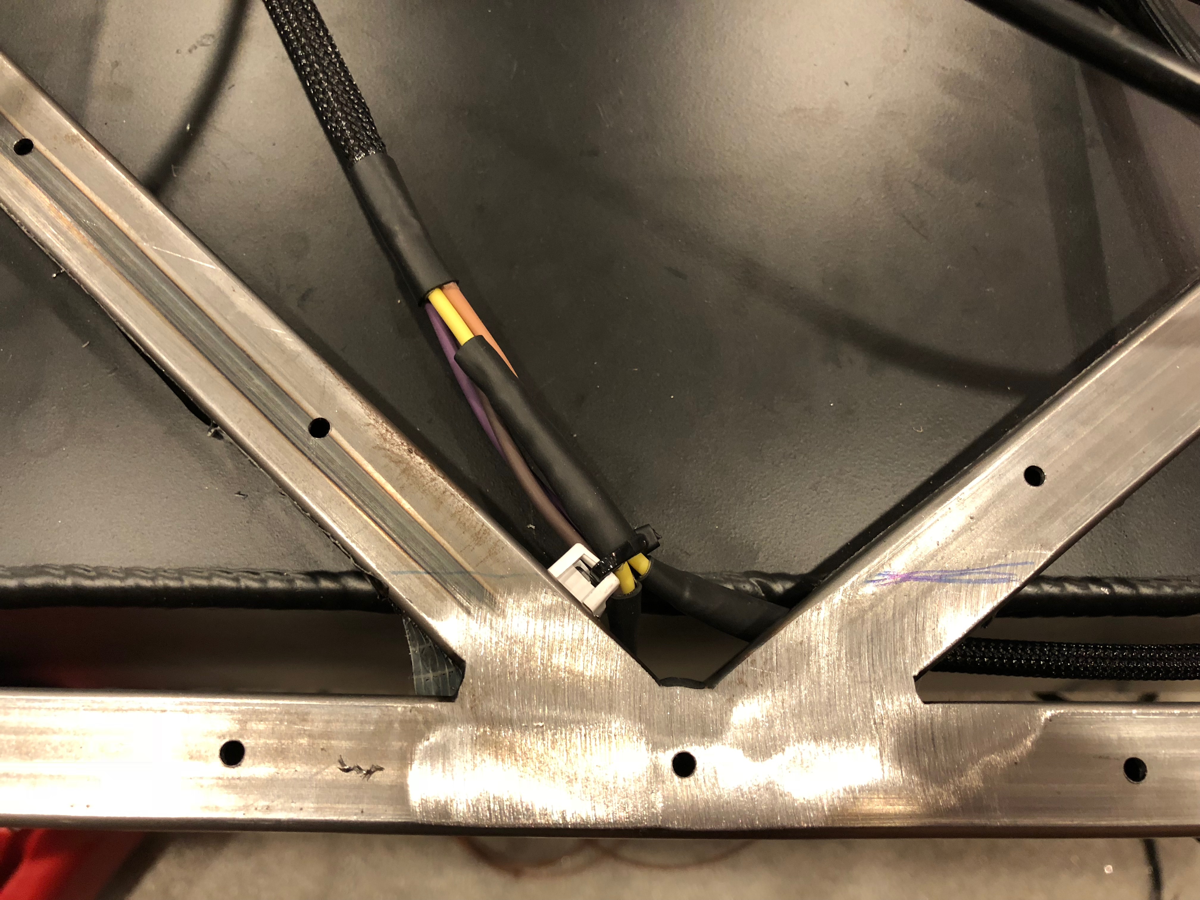
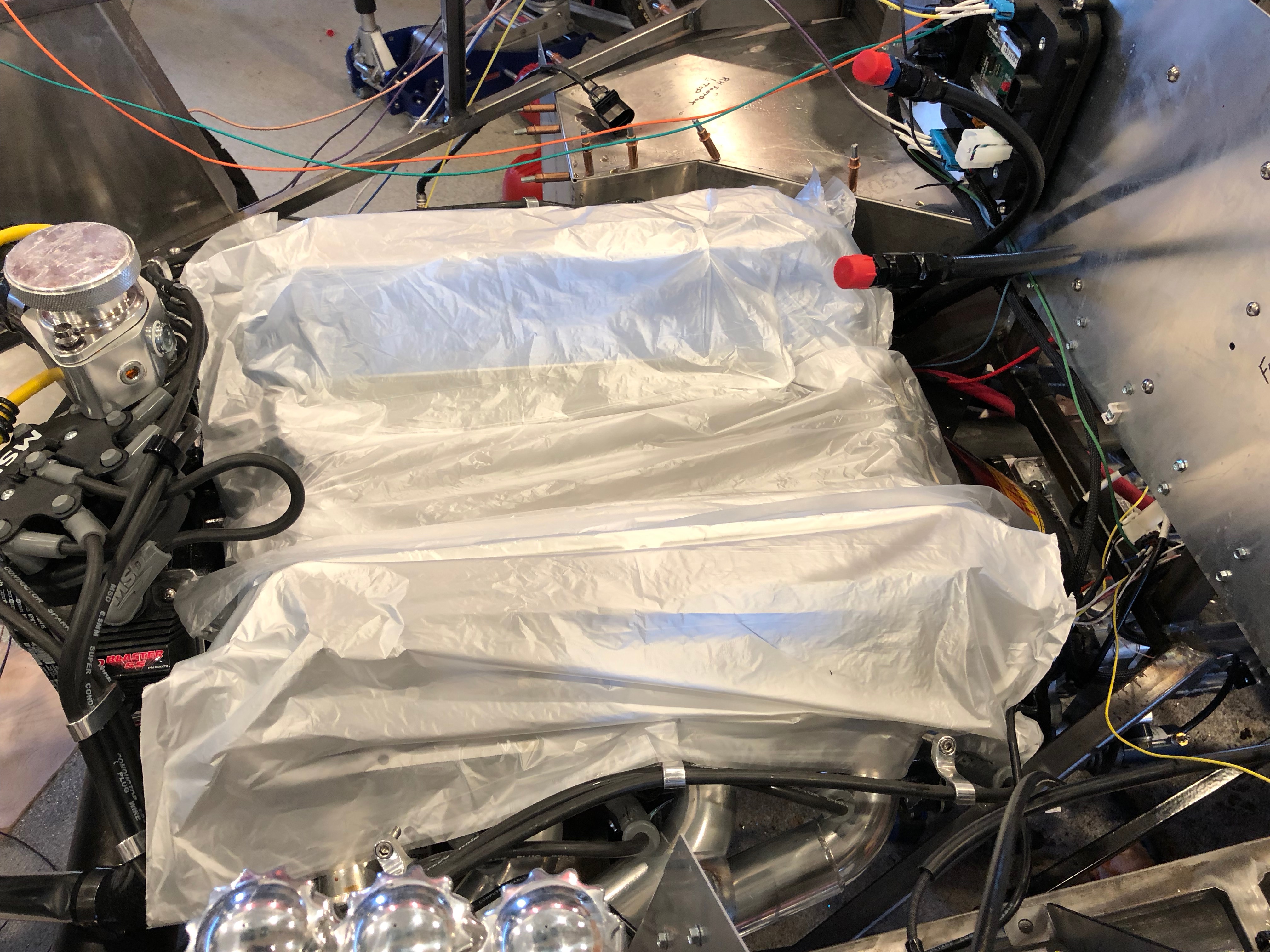
I haven’t posted an update in awhile because my dad and I have been diagnosing some noise in the valvetrain. It’s possible that it’s been there all along and that we only noticed it after installing the mufflers, but we don’t really know. The noise sounded like only 1-2 lifters were making noise, but I couldn’t determine which one with as engine stethoscope. The guidance we originally got from Crane was to set a pre-load of 0.060″-0.090″, so we set it right in the middle at 0.075″. This seemed high based on what we were seeing online, so we reset it to about 0.040″ and tried running the engine again. Unfortunately, the noise got louder. We then tried going to the high end of the range at 0.090″, but the engine wouldn’t run smoothly with that much preload.

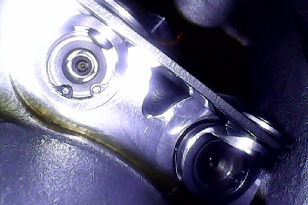
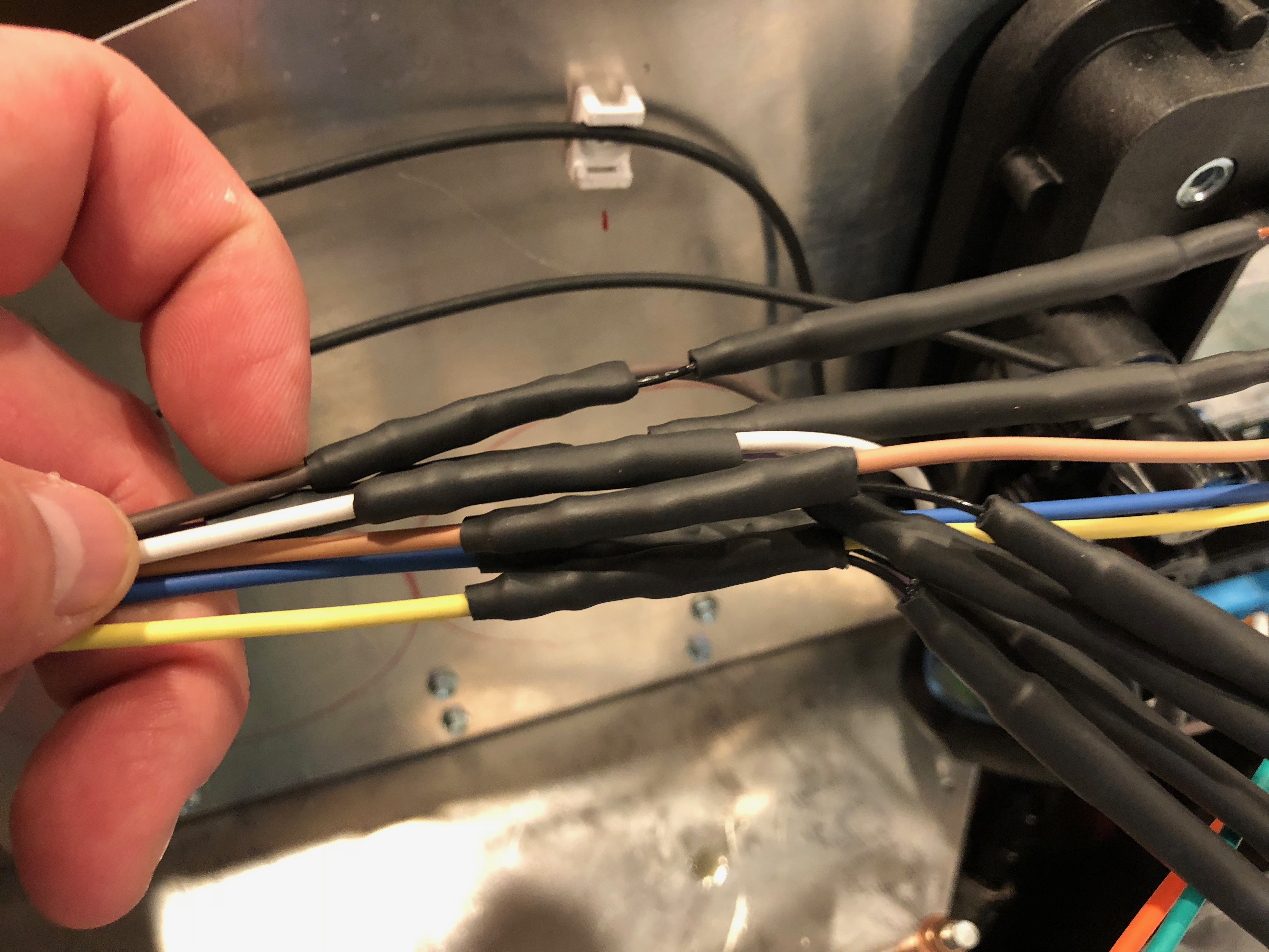
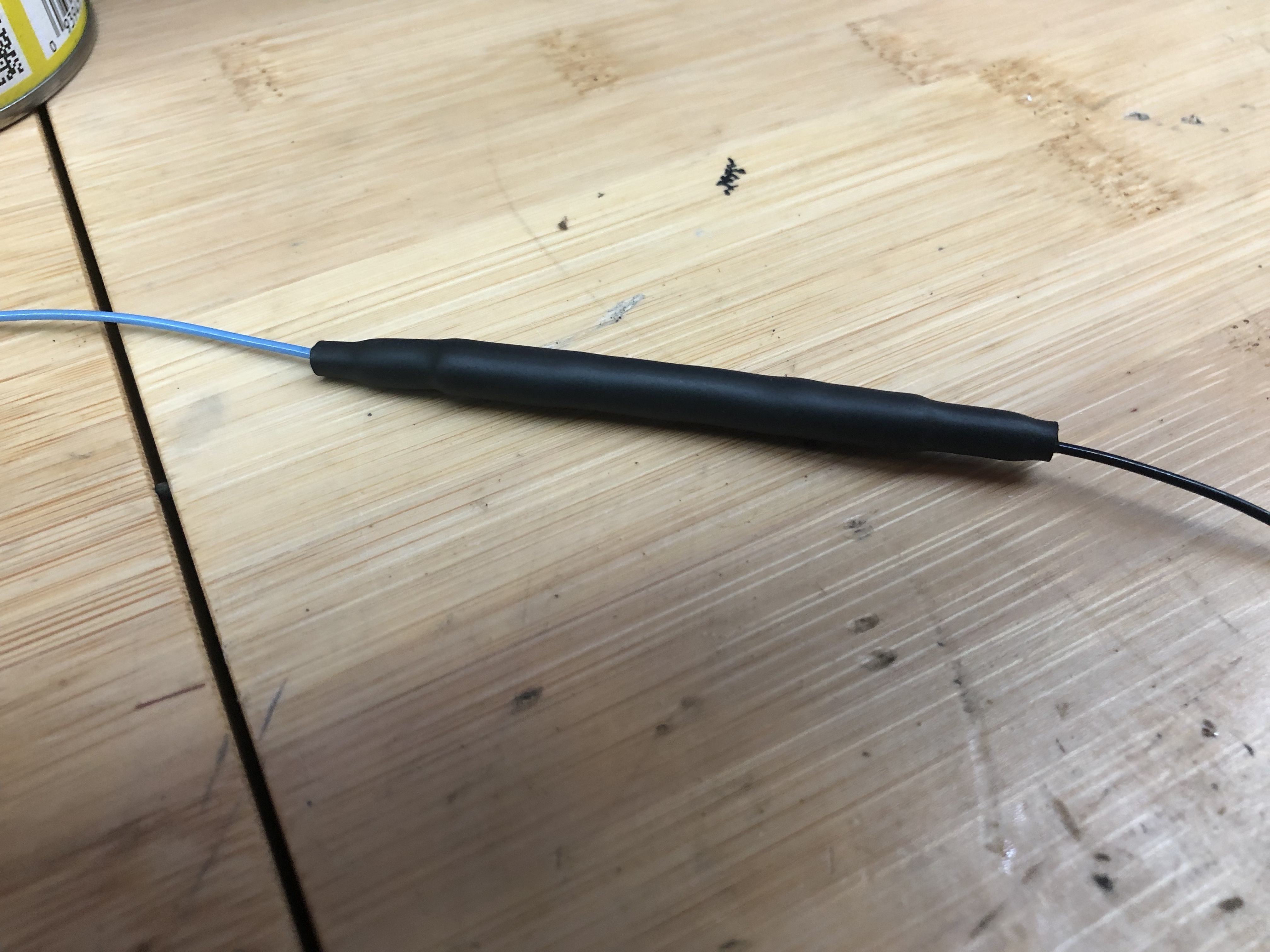
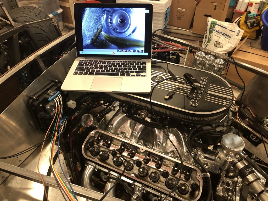
We began to be concerned that the process we were following wasn’t resulting in consistent preload on the lifters. If any of the pistons were partially depressed, we could have significant variation in preload across the lifters. I pulled the valve train back apart again and used an 8.0mm USB inspection camera to inspect all of the lifters. This was only about $20 on Amazon and has a surprisingly good picture for the money.

The tip has 8 LED lights that can be dimmed. The 3M long cable is flexible but will hold its shape when bent.

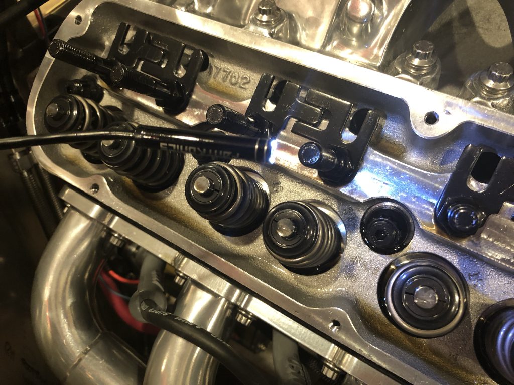
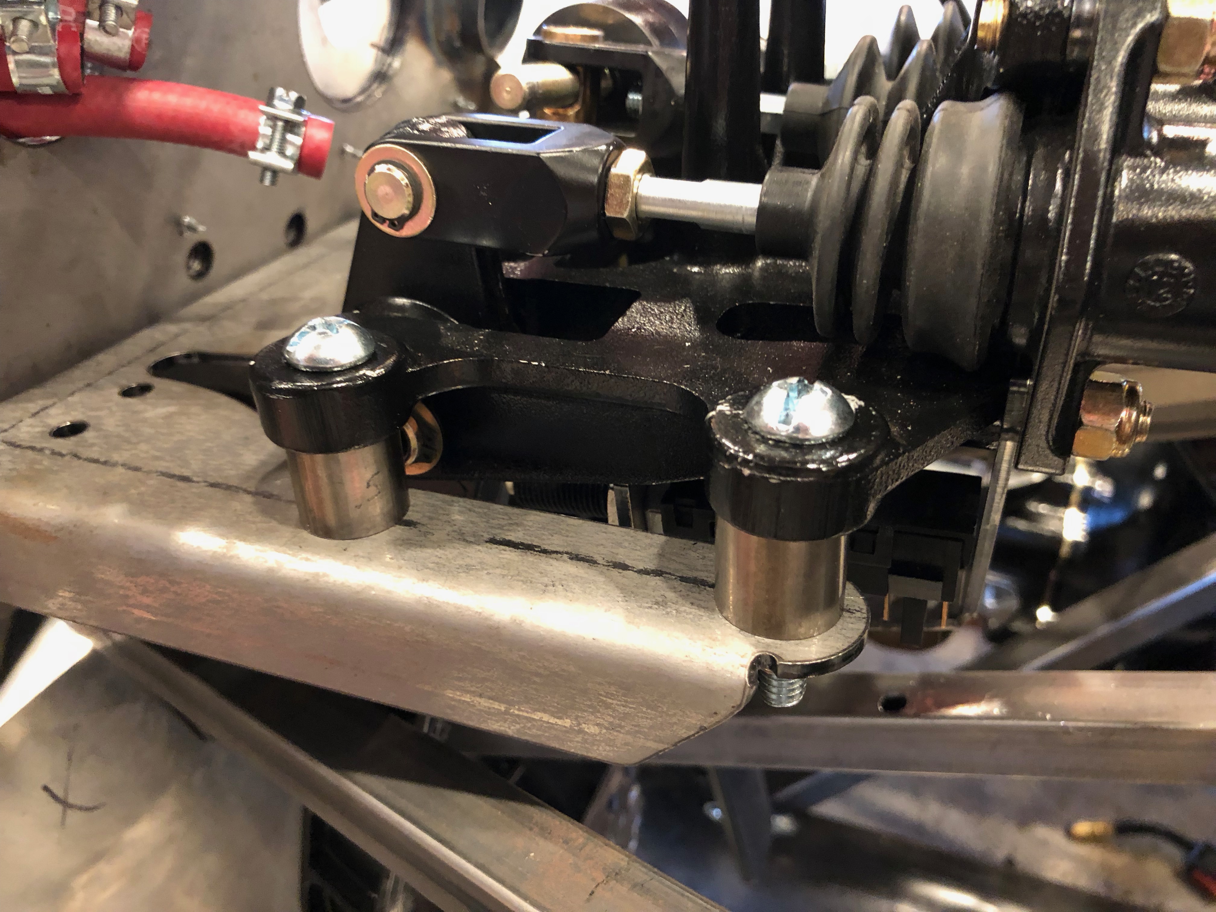
That feature turned out to be handy because I was able to put a curve in the cable and go down through the intake pushrod hole to inspect the exhaust lifter (and vice-versa). This let me look at the lifters at an angle instead of straight on which helped make it more visible that the lifter pistons were at the top of their bores.

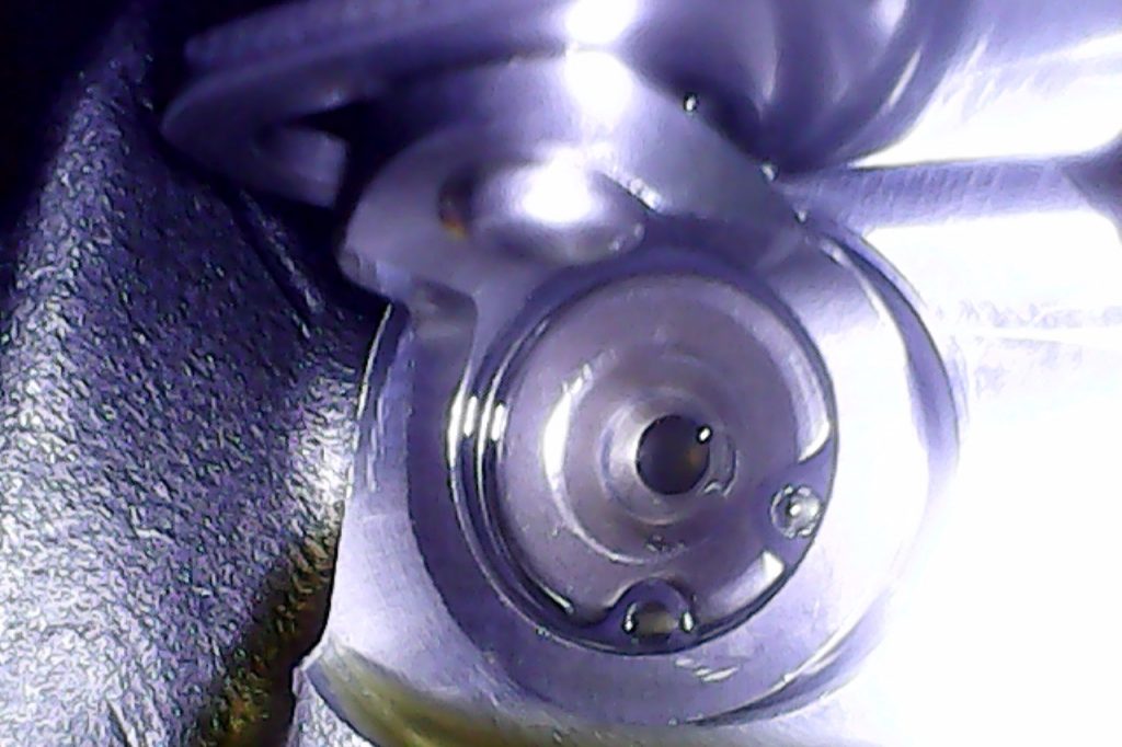
I was also able to pull back a bit and inspect the link bars. Everything looks good, but there may still be a problem that is internal to the lifters (e.g. bad or clogged check valve) that could be causing the problem.