Electric and Final Fuel Lines

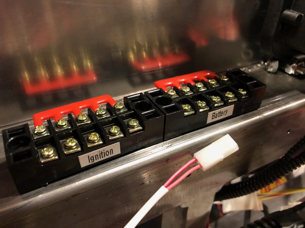
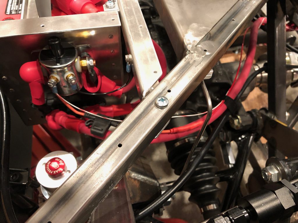
Jenn and I hooked up a number of the circuits connected to the battery and ignition terminal blocks. The rightmost wire in each terminal block is the feed line. The battery terminal block is wired to the starter terminal with a fairly heavy 10AWG wire with inline 30A fuse. The remaining terminals all have smaller inline fuses protecting the wires connecting them to each battery load.

The ignition terminal block is wired to the ignition output on the front load cell. There are still a couple of additional wires to connect to these terminal blocks, but this is enough to get the gauges working and engine running.

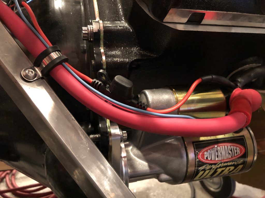
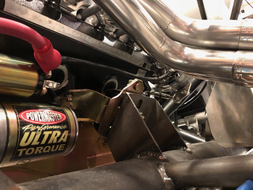
Jenn and I wrapped up the starter wiring with the 30A inline fuse. Normally, the battery feed would be connected directly to the battery to minimize voltage drop during engine cranking, but that is minimal with a 2/0 wire to the starter. I also installed a rivnut to secure the wires to the chassis near the bellhousing.

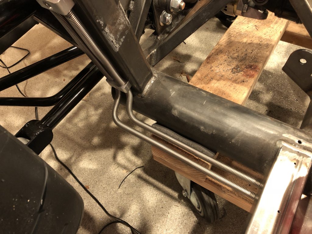
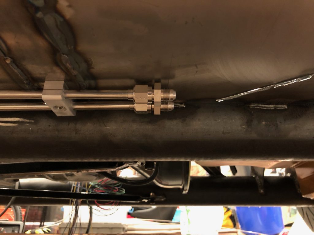
I installed fuel line armor on both the supply and return fuel lines. This is basically just a stainless steel spring that surrounds the tubing to protect against road debris.

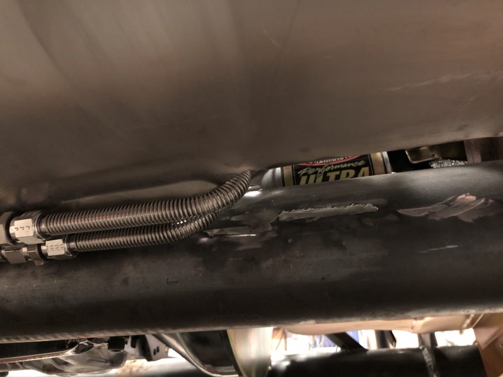
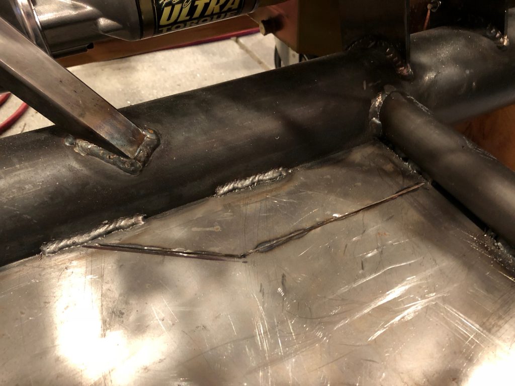
I also fabricated the forward fuel lines that come up through the hole in the floor. It looks like the line is touching the edge of the hole, but that’s just the armor. I may still relieve this a little more when the car comes apart for final assembly.

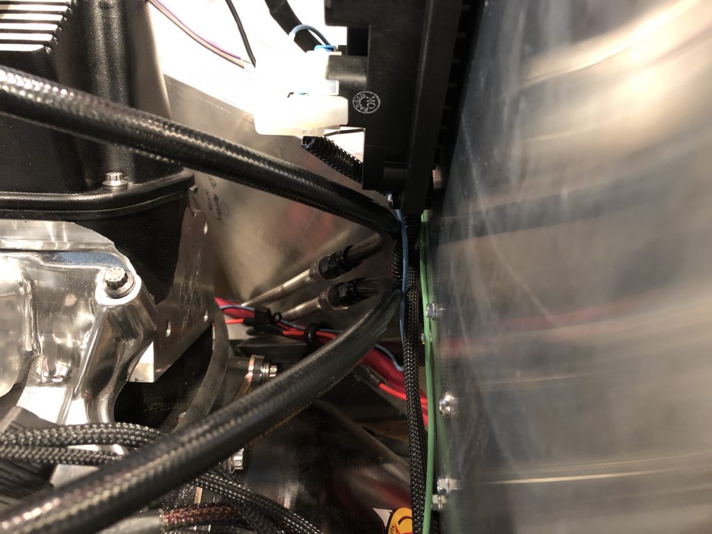
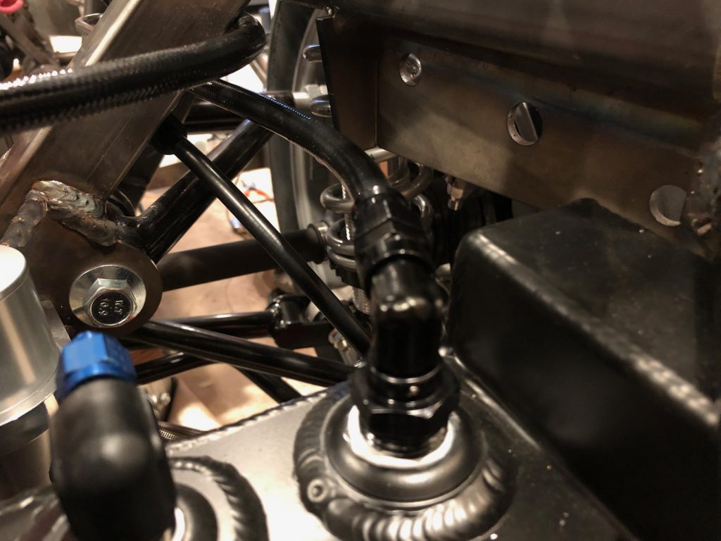
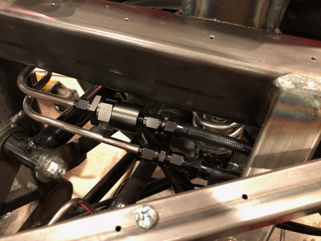
The lines come up just inside the passenger foot box. I then fabricated the final hoses that connect the fuel lines to the throttle body.

Before firing the engine again, I undid the two fuel fittings at the throttle body and connected them together. I run the fuel pump for a minute or so to flush any debris out of the lines. There shouldn’t have been much since I blew out all of the lines and hoses with compressed air, but I’d rather have any small particles end up back in the fuel tank (upstream of two fuel filters) rather than stuck in the throttle body.

After a final check, we restarted the engine for the first time in about four months. It looks like all of the systems are working well together.

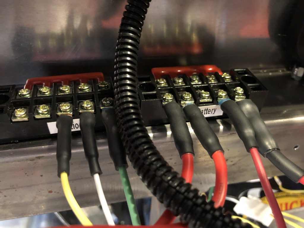
Installed Ignition and Battery Terminal Blocks

There are a number of circuits that need direct battery connections (inRESERVE button, FiTech EFI, clock, GPS keep-alive in the speedometer, and inDASH MAX). There are also a handful of circuits that need power only when the ignition is turned on (electric power steering, FiTech EFI, and voltage gauge). I installed these terminal blocks on top of the 2″x2″ chassis member behind the dash.

More Dash Wiring

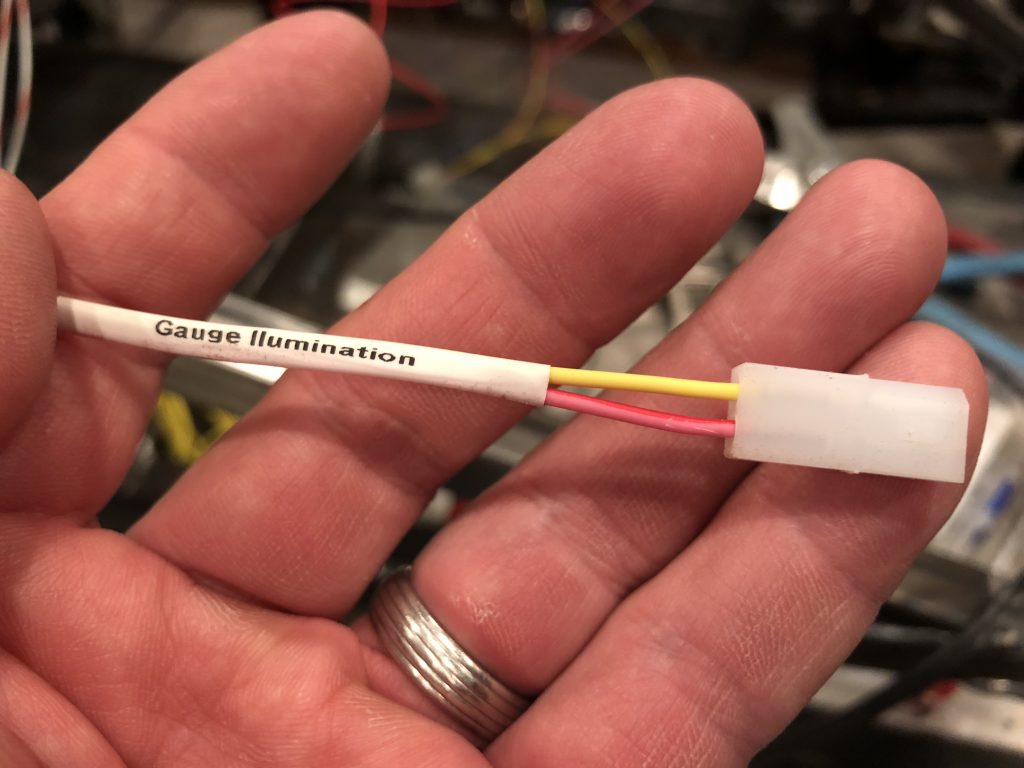
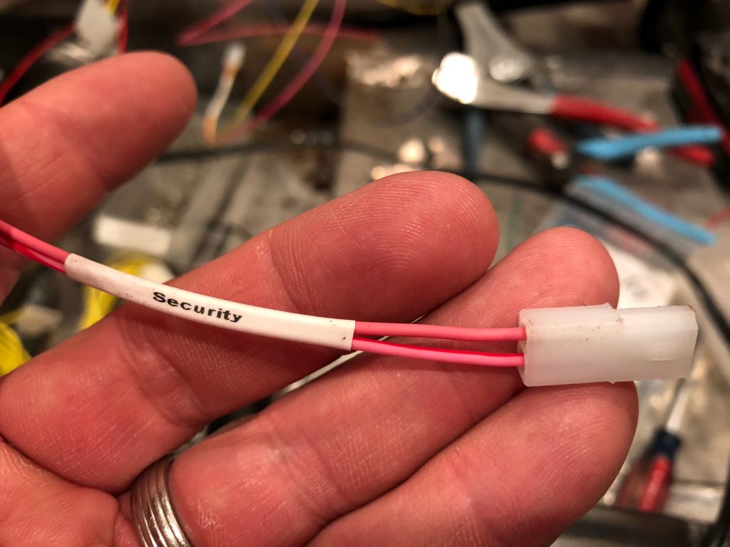
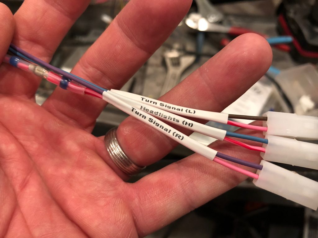
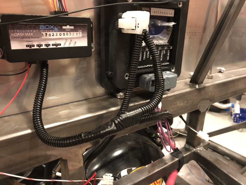
I continued installing connectors in the dash wiring. There are a number of two-conductor connectors in the dash, so I used some heat-shrink labels to indicate where the connector should attach. All of these are from the inDASH MAX box.

This will flash the security light when the system is armed.

The three indicators above the steering wheel share a power wire that is split inside the solder-sleeve on the left side.

I also shortened the CAN bus cable and tied in the inDASH MAX network wires.

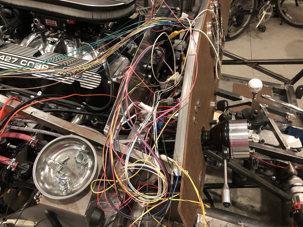
The wiring looks like a bit of a rat’s nest, but that’s because I’m leaving all of the wires to the dash long for now. Once I have all the wires connected, I’ll cut them and install a single, large connector that should make it easy to remove the dash.

Dash Wiring

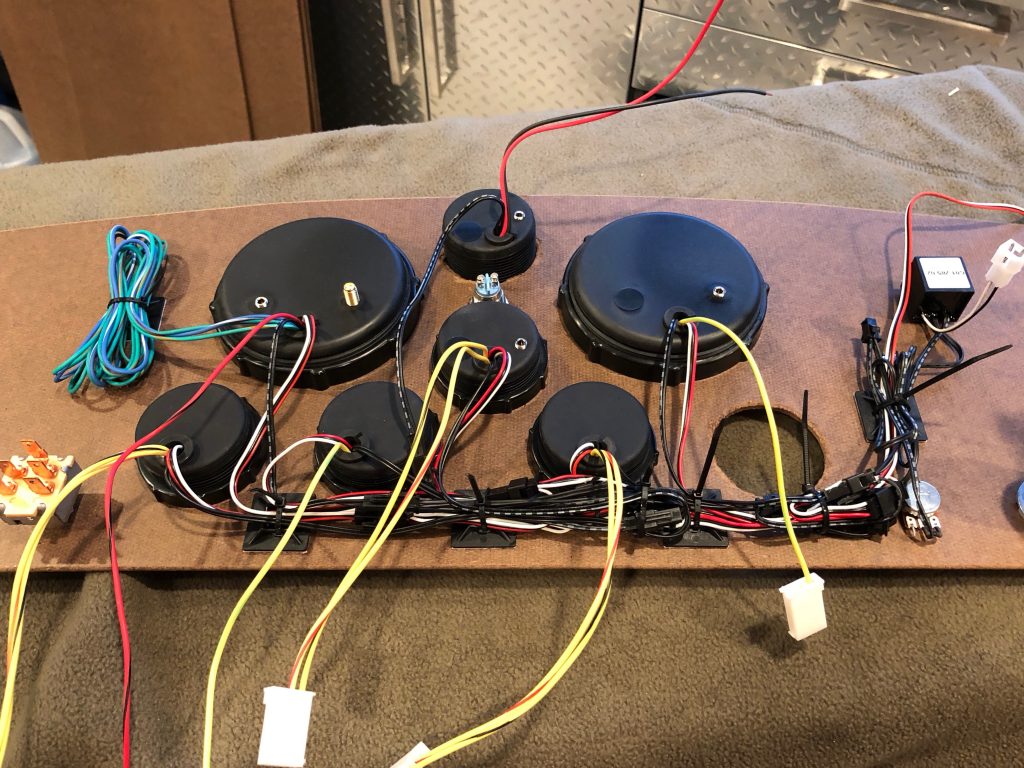
I’m putting connectors inline with all dash components to make it easy to remove them. I cut pieces of the same wire to make it clear that the connector is installed to the right component.

I removed the dash and hooked up the power and lighting connectors. I zip-tied the wires to some self-adhesive mounts along the bottom of the dash. The bundle of wires in the upper left are lighting wires for the turn signal and high-beam indicators in the speedometer. We’re not using those since we have dedicated indicators.

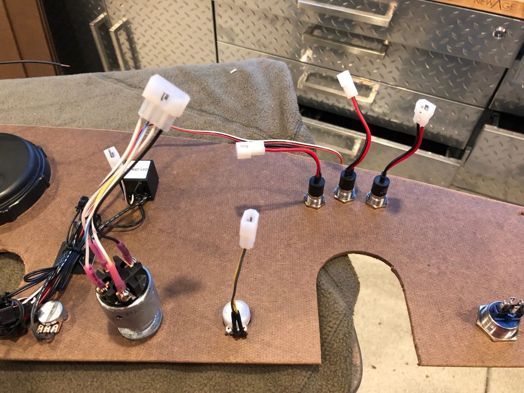
I added connectors to the lighting inverted, power steering potentiometer and indicator lights over the steering wheel.

Prototype Dashboard

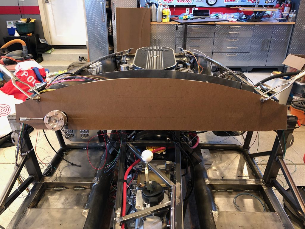
We’re still working on our final dash shape and layout, but we need to move forward with wiring. I used a piece of hardboard to make a prototype dash that we can use to do the preliminary wiring and evaluate our initial layout. A single piece of 4×8 hardboard costs about $12 and includes enough material to make about 8 prototype dashes.

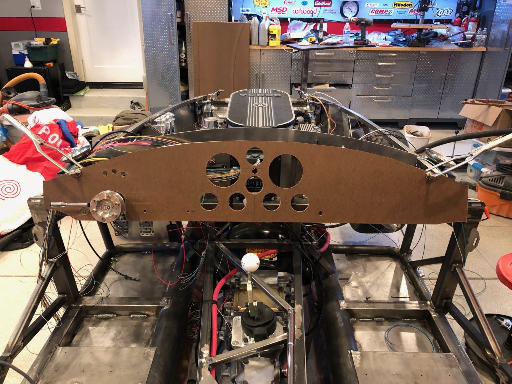
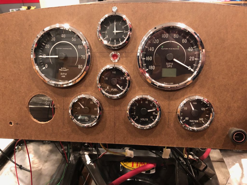
I laid out and cut the holes in the dash. We haven’t decided where to put the ignition switch yet and I’m sure some of the other items will move, but this is a good starting point. One issue I noticed right off the bat is that the top center hole is too high. There is a 3/4″ square tubing along the top of the dash and the top of the hole just lines up with the bottom of the tubing. The gauge fits in fine, but there’s not enough room to thread on the ring that secures the gauge in place.

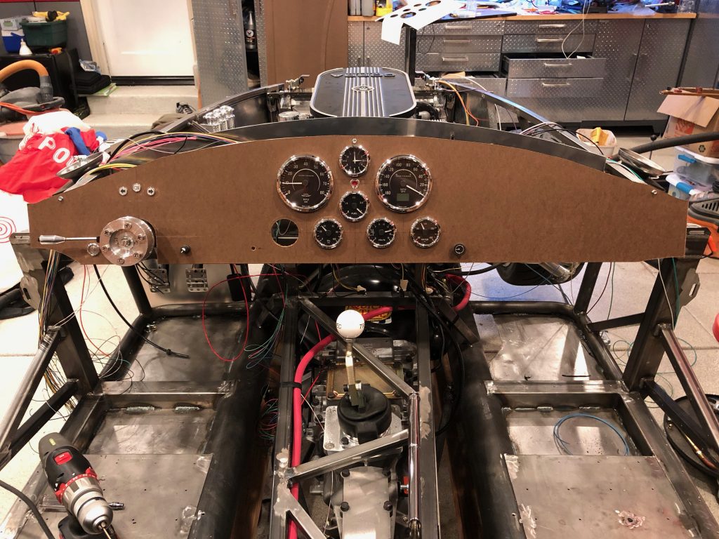
I pulled the dash and then installed most of the components.

Here’s a closeup of the gauge cluster. The empty hole at the lower left of the cluster will be for an oil temperature gauge. This doesn’t come with the gauge set from FFR, but we’ll either buy one to match or will be buying a whole new gauge set to match our interior.

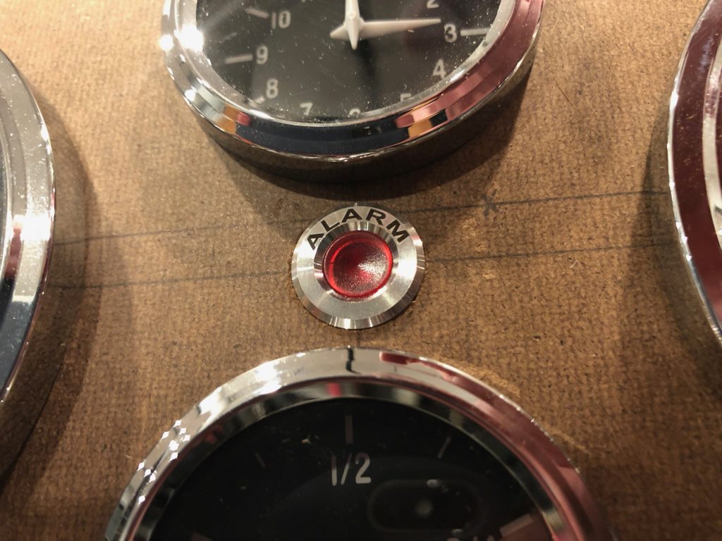
We installed the alarm light in the middle of the gauge cluster. I’m not sure I like it here, but we’ll sit with it for now and see how we feel about it.

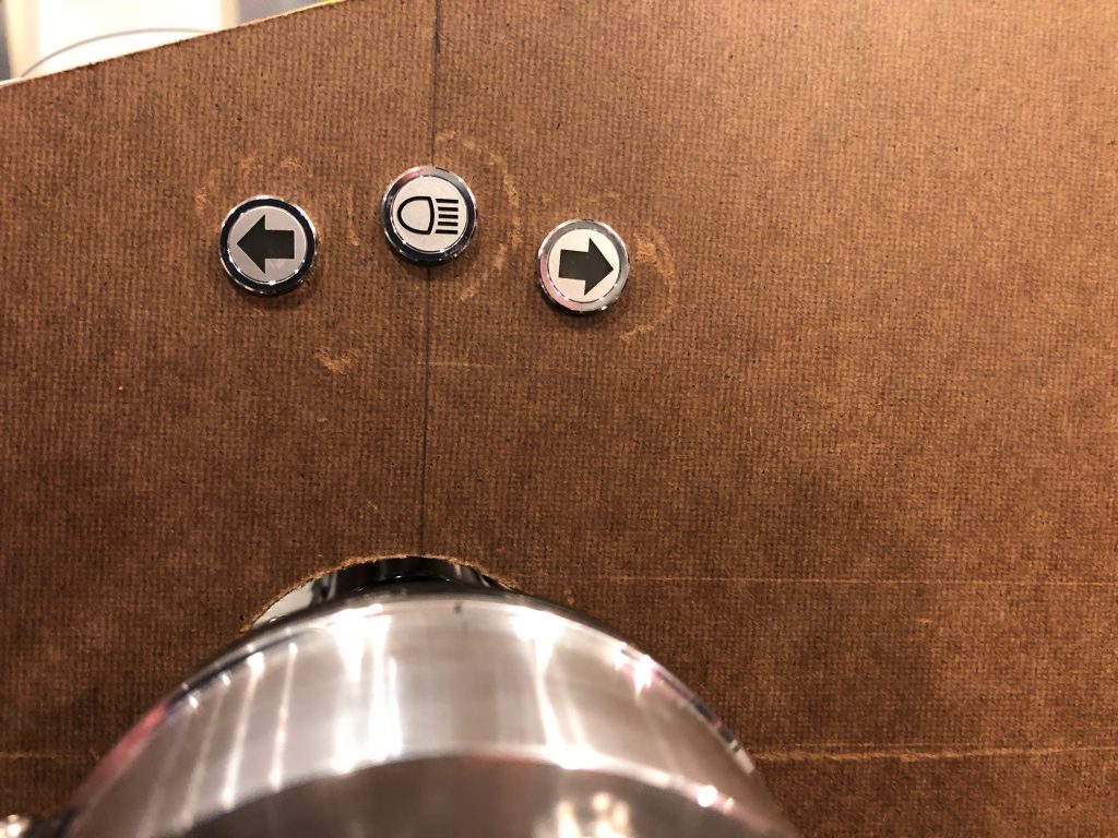
Just over the steering wheel are the indicators for the high beams and turn signals.

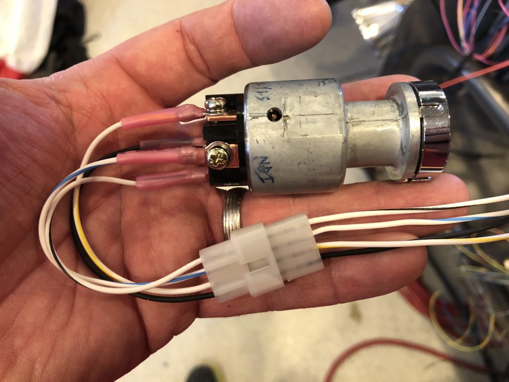
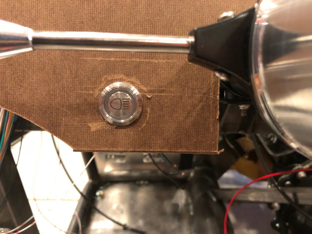
Just to the left of the steering wheel is the high beam toggle. When the headlights are off, this will function as a flash-to-pass button where the headlights will be on while the button is held down. When the headlights are on, this will toggle between the low and high beams.

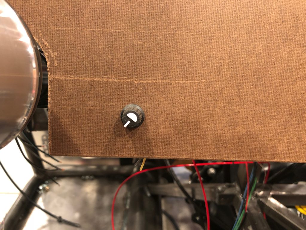
To the right of the steering where is the power steering adjustment knob. This will let us adjust the power steering from completely off to maximum assistance.

Primary Power Wires

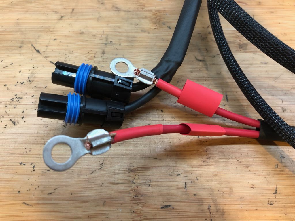
Jenn finally had some time to work on the project, so we got started by installing the primary power wires to the two load cells. I cut them to length and then crimped on the terminals. I slipped the heat shrink over the crimps after taking this picture, but I wanted to show how nice the crimps come out from the hydraulic crimper from Harbor Freight.

Installed Shift Ball

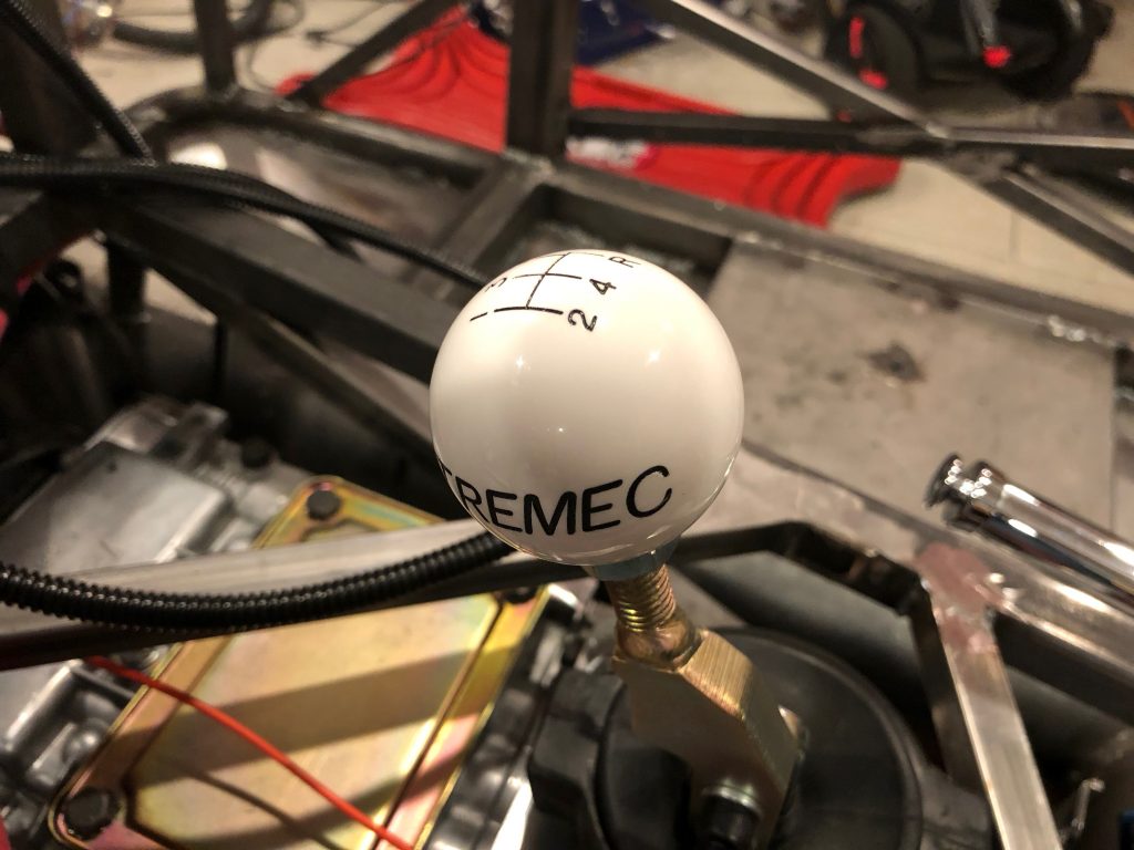
We haven’t been able to install the shift ball because the threads in the ball (M16x1.5) don’t match up with the shift lever (M12-1.75) and the ball didn’t come with the right adapter. I contacted Epco Manufacturing (the maker of the shift ball) over a week ago but still haven’t received a response, so I ordered one from Summit.

Resumed Work on Fuel Lines

I resumed work on the fuel lines tonight and got started by fabricating the fuel return line. I used a special 90º swivel fitting with 1/2 NPT threads instead of installing a 1/2 NPT to -6 AN adaptor and then a 90º AN fitting on the hose becase this doesn’t stick up as far. Even this sticks above the top of the fuel tank by nearly 1/2″, and the trunk floor is only 3/4″ above the top of the trunk. I made the hose about 1/2″ longer than necessary to put a small bend in it. This will prevent the hose from being pulled tight if the tank moves around a bit.

The return line connects just below the supply line with the filter.

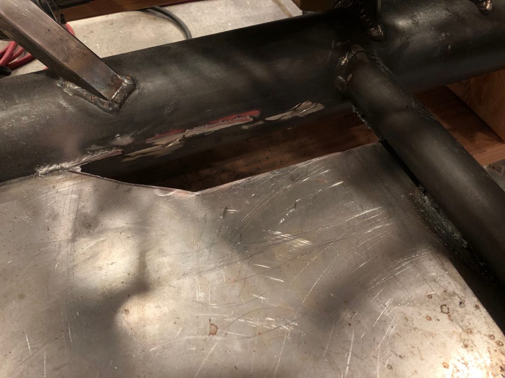
The fuel lines run just outside the right main 4″ chassis tube. I briefly considered bringing them up in front of the passenger foot box, but that would put them very close to the right exhaust header. Instead, I marked and began cutting a hole in the passenger foot box floor to bring the fuel lines up farther back and farther away from the exhaust headers. The cut lines follow the inner wall of the passenger foot box. I’ll fabricate some flanges to rivet the wall to the floor along these edges.

I cut the fuel lines just aft of this hole and flared them for some fittings. I’ll fabricate some shorter tubing sections later to run from here up behind the engine in the engine bay. There will be hose segments connecting the rigid tubing to the engine to allow for engine movement.

Starter and Alternator Wiring

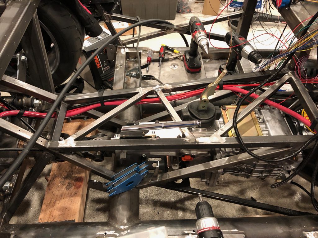
I installed the 2/0 AWG starter cable tonight. It starts at the output side of the mega fuse and follows the right parking brake cable forward to the aft end of the transmission tunnel.

It crosses over to the left side of the tunnel and then up the left side past the shifter and then cuts back to the right at the forward end of the tunnel.

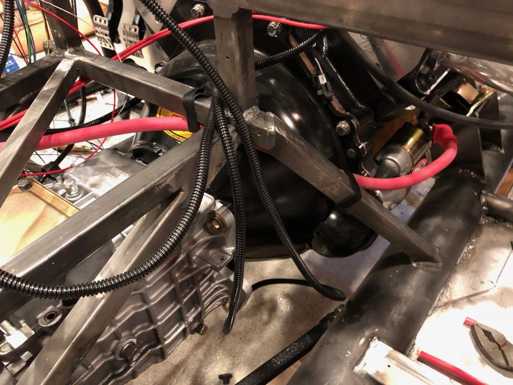
It travels down the diagonal tunnel support member and then attaches to the starter. I’ll secure this with adel clamps when I have run all the wires through the transmission tunnel.

I also installed a 4 AWG cable from the alternator to the starter. This is covered in black expandable sleeving and black heat shrink tubing in keeping with the color theme of the engine bay.