Soldered Hazard Light Circuit

I picked up a handful of these solderable breadboards and soldered up the hazard light circuit with a couple of I/O connectors. Before installing it, I verified the circuit still worked as expected.

I also picked up some of these small plastic enclosures. I cut some access ports on the side using the mill that align with the connectors and then threw a few labels on it.

Wiring Cleanup

I started trying to organize the wiring a bit and shortening some of the long wires that I had coiled up behind the dash.

When I powered everything back up though, the indicator lights in the panel weren’t working. Somehow in the process of shortening the wires, one of the power wires coming from the inDASH Max box must have hit the chassis and blew the internal fuse. I opened it up, and it uses these incredibly tiny micro fuses. I verified one of the two had blown and ordered some replacements. The came a couple of days later and I verified that the replacement fuse fixed the problem.

Hazard Circuit

The buttons in the button panel I showed yesterday have LED rings around them that will light up when the corresponding function is turned on. Most of these are pretty simple since there is a single output wire from the front POWERCELL for each of the functions. I tapped into each of these wires and will power these LEDs from them.

The hazards are a different matter though. There’s not a separate output from the POWERCELL for the hazard lights. Instead, the power cell flashes both left and right turn signals in unison. I obviously don’t want the hazard button to flash whenever a turn signal is on; it should only turn on when both turn signals are on at the same time. Essentially, I need an AND gate for 12V signals that is capable of flowing enough current to drive these LEDs.

Fortunately, that’s a pretty trivial circuit to build with a couple of NPN transistors and a few resistors. The two upper yellow wires represent the left and right turn signal wires. When both are plugged in to the power rail adjacent to the red line, the LEDs turn on, but if either wire is removed from 12V (as would happen if only a single turn signal is turned on), the LED is off.

I have some small breadboards coming in a couple of days and will solder up this circuit to be installed in the car.

Prototype Button Panel and Lighting

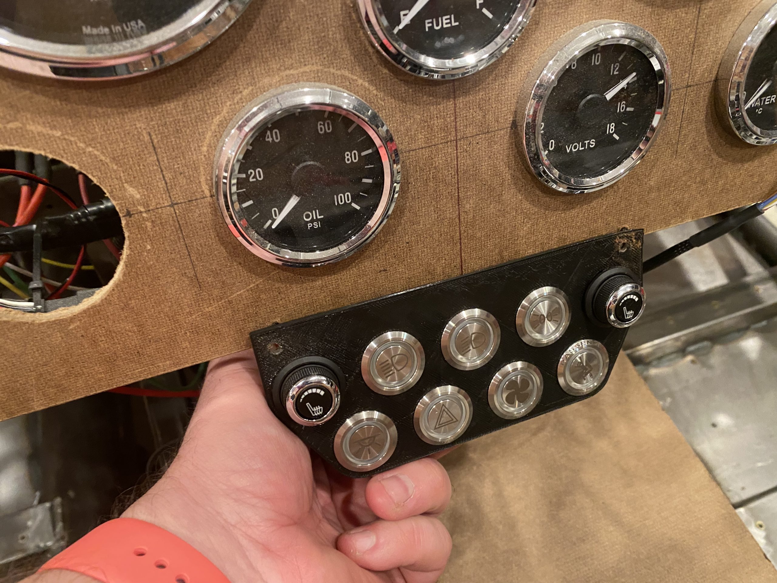
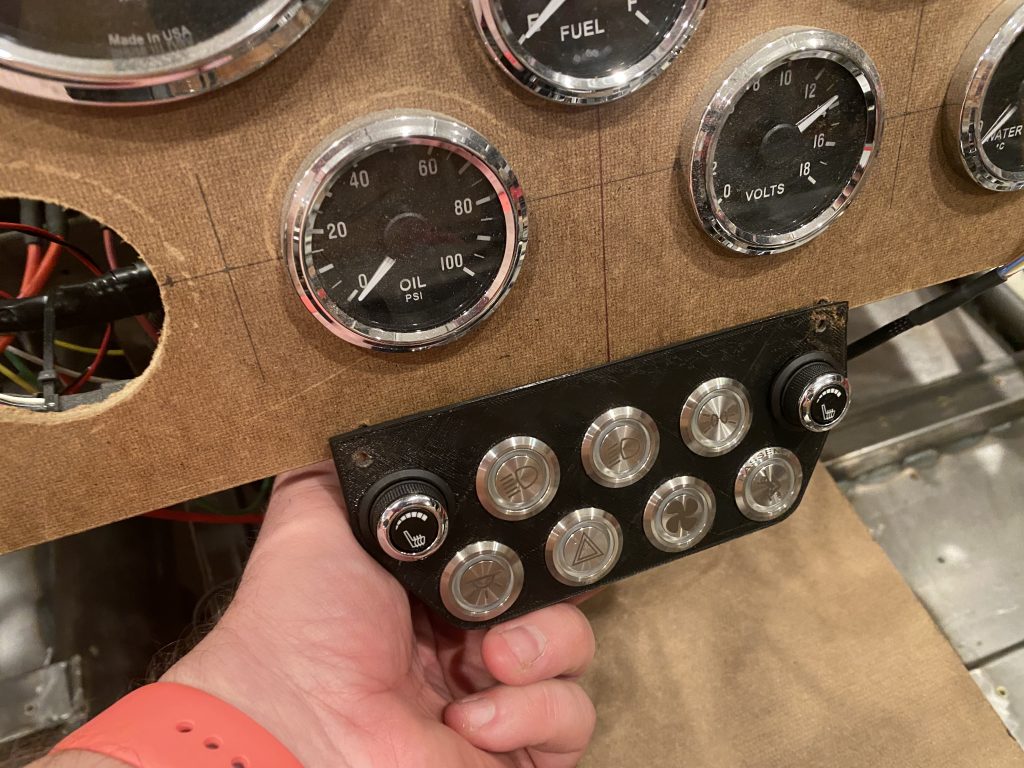
I 3D printed a prototype button panel. Ultimately, I’ll fabricate something that sits below the dash and is recessed somewhat. That will make it easily reachable, but not in the way of shifting.

The final button arrangement hasn’t been determined, but the initial layout places the seat heater controls on the top row at each end and all exterior lighting between them. Starting from the right is a button for the parking lights. The middle light will turn on the headlights (which will also turn on the parking lights if they’re off). Finally, the left button is the high/low beam toggle. I considered putting these near the steering wheel somewhere, but any location along the bottom of the dash is obscured by the steering wheel. Any higher location is easily visible, but more awkward to reach.

The bottom row has an assortment of buttons. Starting from the left, the first button is for the interior lights. These will come on automatically when the alarm is disarmed or when the car is turned off. The second button is the hazards. The third button is the fan override, and the final button is the passenger eject button.

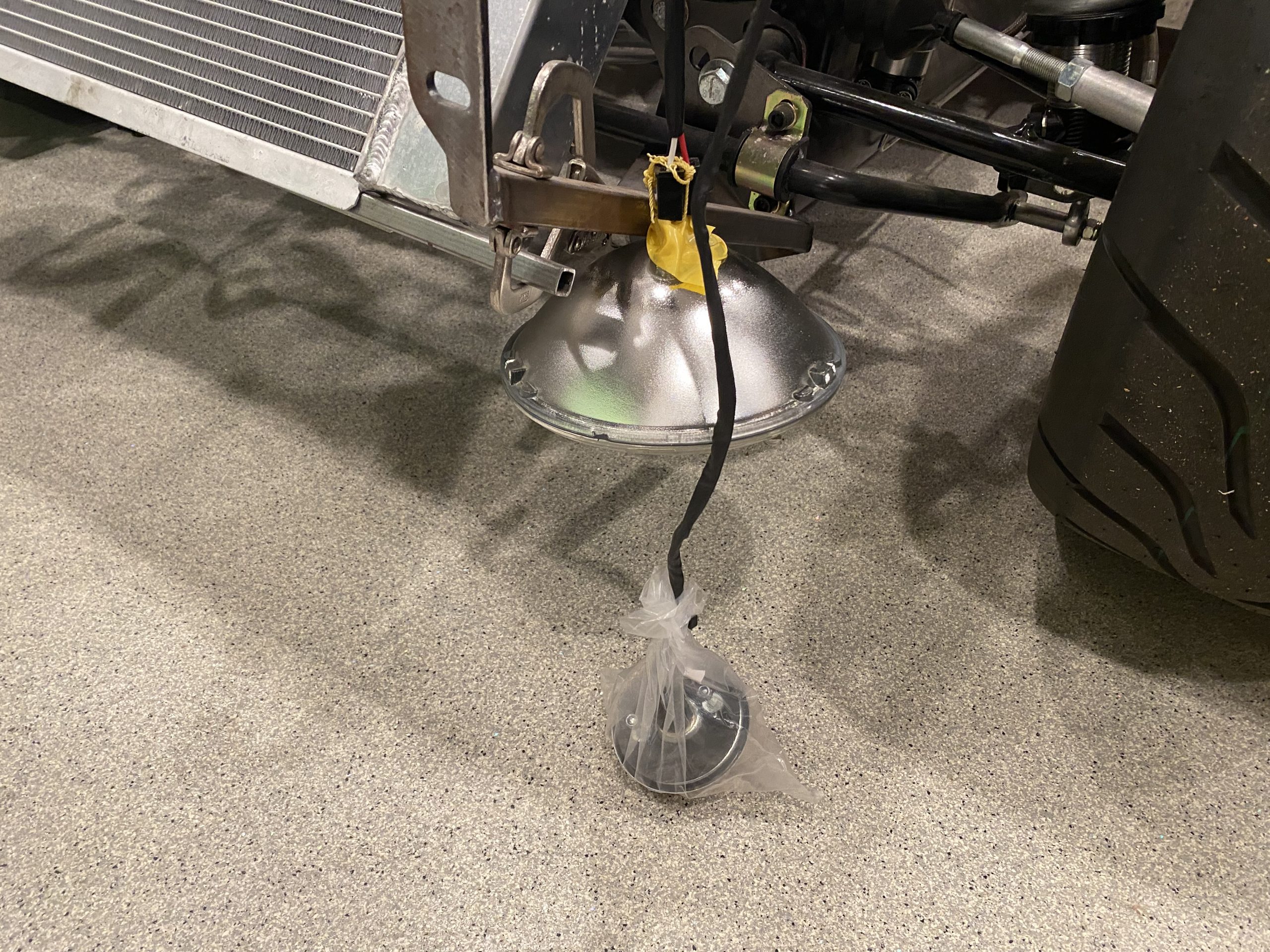
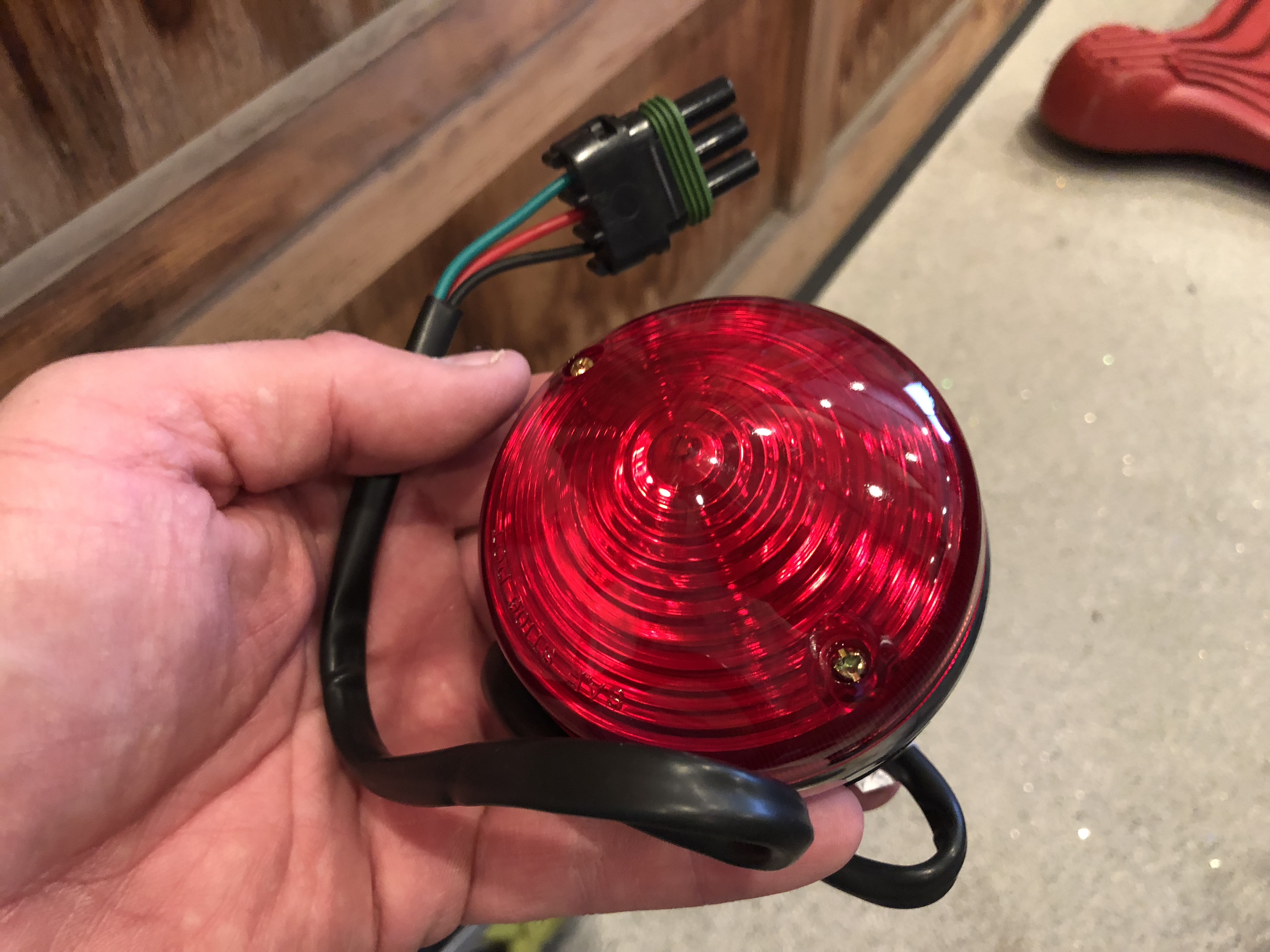
I hooked up all of the exterior lights to verify they worked, and ran into an odd behavior. When the right turn signal was turned on, it worked correctly, but when the left turn signal was turned on, both left and right turn signals flashed dimly.

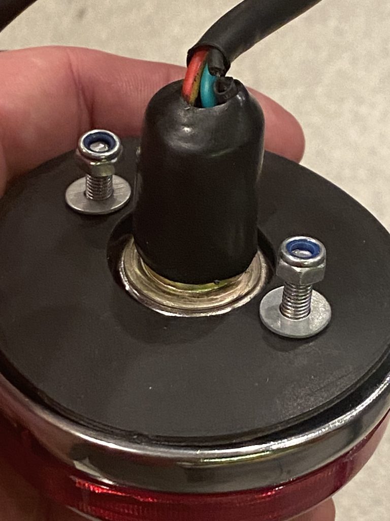
When I diagnosed the issue, I found out that one of the tail lights had a broken ground wire. This was causing power flowing into the turn signal to flow back through the brake light filament (through the shared ground in the bulb) and into the brake light of the opposite tail light. If it’s easy to fix, I’ll do that; otherwise I’ll call Factory Five to get a replacement.

Update: the wire broke right at the solder joint. I removed the heat shrink and re-soldered the ground, and everything now works correctly.

Grounding Block Behind Dash

I added an additional terminal block behind the panel for grounding various items. It’s grounded locally through the jumper wire down to the 2″x2″ chassis member.

I had to remove the brake biasing knob to install the rivnut for the grounding wire.

While I had the knob out, I installed a couple of 8-32 rivnuts and used some of the torx-drive screws. I had previously used some sheet metal screws, but I’m trying to eliminate all of them.

Wiring Connectors and Rear Brake Line

My order of Weather Pack connectors showed up, so I installed the remaining ones that were missing. For the headlights, I also fabricated short jumper cables to the plug that attaches to the back of the bulb. When I switch to LED bulbs, they might have a different connector on the back, so it will be trivial to fabricate a different jumper if necessary.

I also got started on the rear brake line. This line runs from the forward side of the pilot’s footbox, along the upper 3/4″ tubing to the x-frame and down to the main 4″ chassis tubing. There will be a union there to the piece of tubing that runs the rest of the way to the rear tee.

Chassis Rivnuts & Front End Wiring

I knocked out a bunch more of the chassis rivnuts that will secure the aluminum panels. Unfortunately, the 8-32 mandrel broke after a couple hundred, so I had to stop. Astro Pneumatic has a 1 year warranty and claims they will replace any component that fails under normal use, so we’ll see if they cover this. In the mean time, I have plenty of other things to work on.

Three of the wires in the front chassis wiring harness (parking lights, low beams and high beams) need to be split and run to both the front left corner and front right corner. I stripped the insulation and used a few solder sleeves to splice into the wires. The bundle for the front left corner (which also includes the left turn signal) cuts under the chassis tubing and runs across the top edge of the radiator, secured by some adel clamps.

I ran out of three-conductor Weather Pack connectors, so I just terminated these with the appropriate plugs and seals. There will be two connectors here: one connector for the headlights with a ground wire, low and high beam wires, and another connector for the indicator light with a ground wire, parking light, and right turn signal.

Another pair of wires drop down to the lower chassis tubing for the fan wiring. There will be a rivnut and zip-tie mounting block installed here, but it’s just zip-tied for now.

From there, it runs across to the fan. There will be a couple more attachment points across the lower edge of the fan shroud to secure this cable.

The cable that cuts across the top of the radiator runs down the left chassis member and terminates in a similar set of six wires. The two ground wires are secured to the chassis with a screw behind the bundle of four terminals to the left.

Taillight Wiring and Clutch Pedal Clearance

I installed Weather Pack connectors on several of the tail lights. I ran out of three-conductor connectors though, so I couldn’t finish all of them.

I also installed the female connectors on the chassis on both sides. These are electrically identical and all lights have identical connectors. This is possible because the InfinityBox lets you use the same lights for brakes and turn signals. Although this is possible with a combination of relays in a traditional wiring harness, most builders don’t wire it this way. They end up using the dim filaments in all four tail lights for their parking lights, but the bright filaments in one pair of lights for the brakes and in the other pair of lights for the turn signals. In our car, all four bright filaments will be used for brakes and turn signals.

When I moved the pedal box up, it caused interference with the 3/4″ tubing that cuts through the middle part of the driver footbox. There must have been some stress in this tubing because the two pieces shifted out of alignment with each other when cut apart. I’ll weld in a new piece of 3/4″ tubing on the outside of this tubing. I’ll try and realign the pieces of tubing when welding.

It took a few extra trims on the forward end of the tubing to allow the pedal to go all the way to the front of the footbox, but I now have full clutch travel.

Horn and Taillight Wiring

I cut back the sleeving on the wiring harness to the front right of the car and put a terminating piece of heat shrink on it to keep it from unraveling. I then cut the horn wire and created a jumper between the horns.

I also installed a grounding point on the forward 3/4″ tubing and grounded the horn there. The lights and fan will also ground here.

The ground wire also jumpers between the two horns.

I also added a grounding point on the left side diagonal chassis member to ground the rear load cell.

I figured out which wires will be routed to the rear lights and put some expandable sleeving over them. I’m routing them over the top of the fuel tank.

I used a solder sleeve to tee the parking light wire and then dropped the wires down behind the tank near the center.

Wiring Harness and Horns

I slipped some expandable sleeving over the bundle of wires going to the front of the car and secured the harness to the firewall to the left of the load cell.

The harness routes under the upper chassis tube and is secured to the outside.

The harness will split at the top of the radiator and route to the various loads at the front of the car: lights, fan, and horn. I went ahead and installed the horns along the upper tubing beside the radiator.