Prepping Engine for Dyno Shop

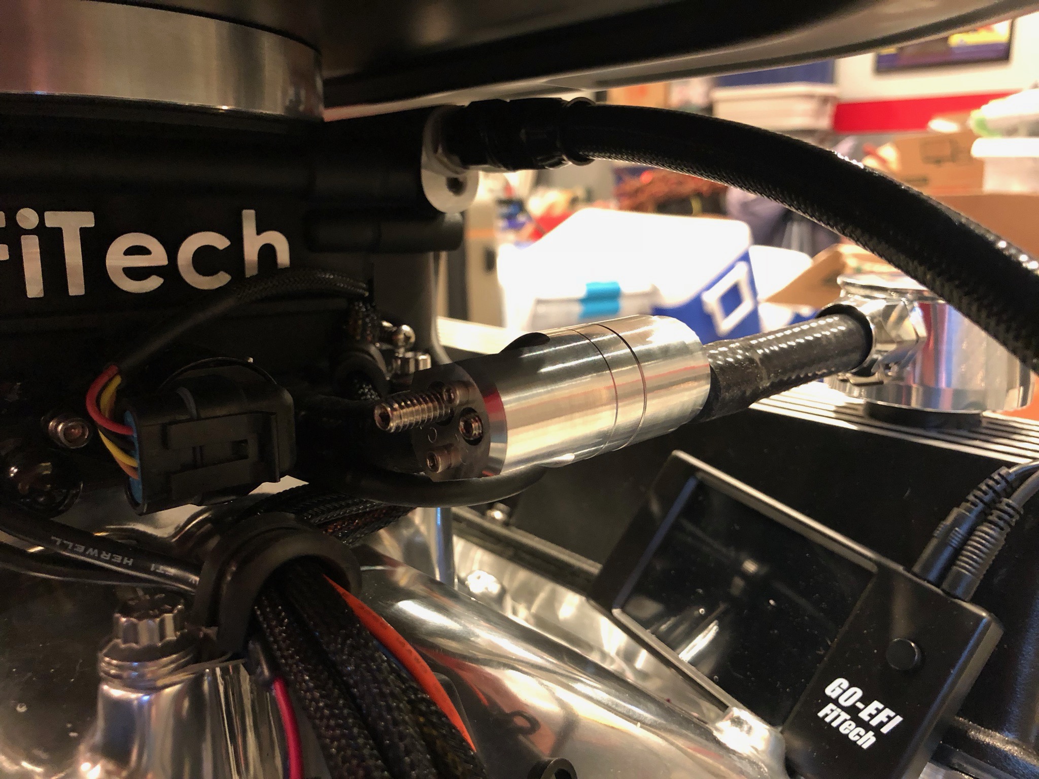
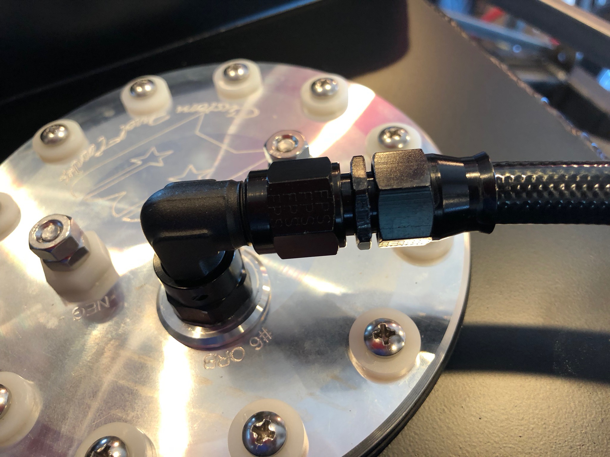
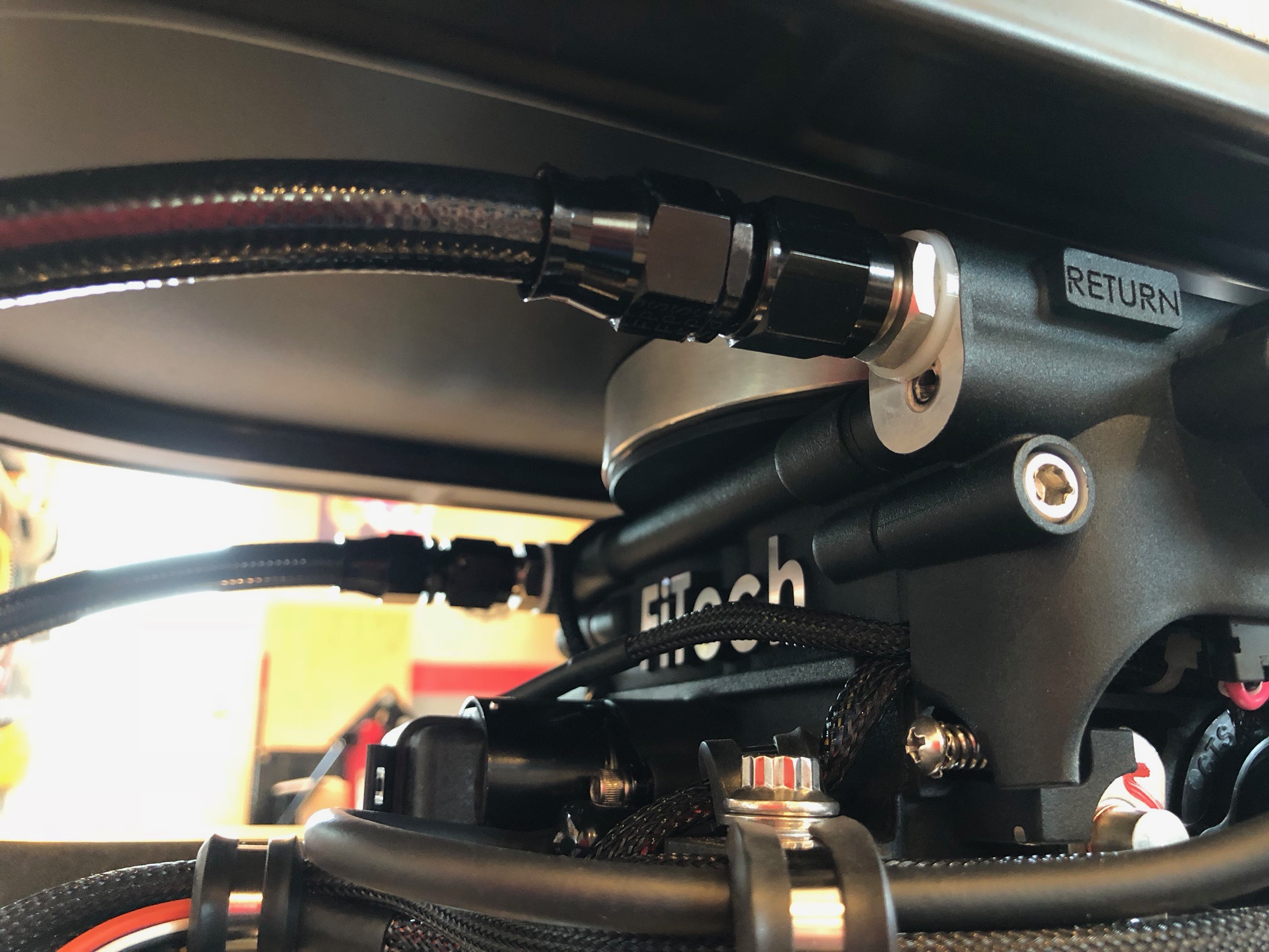
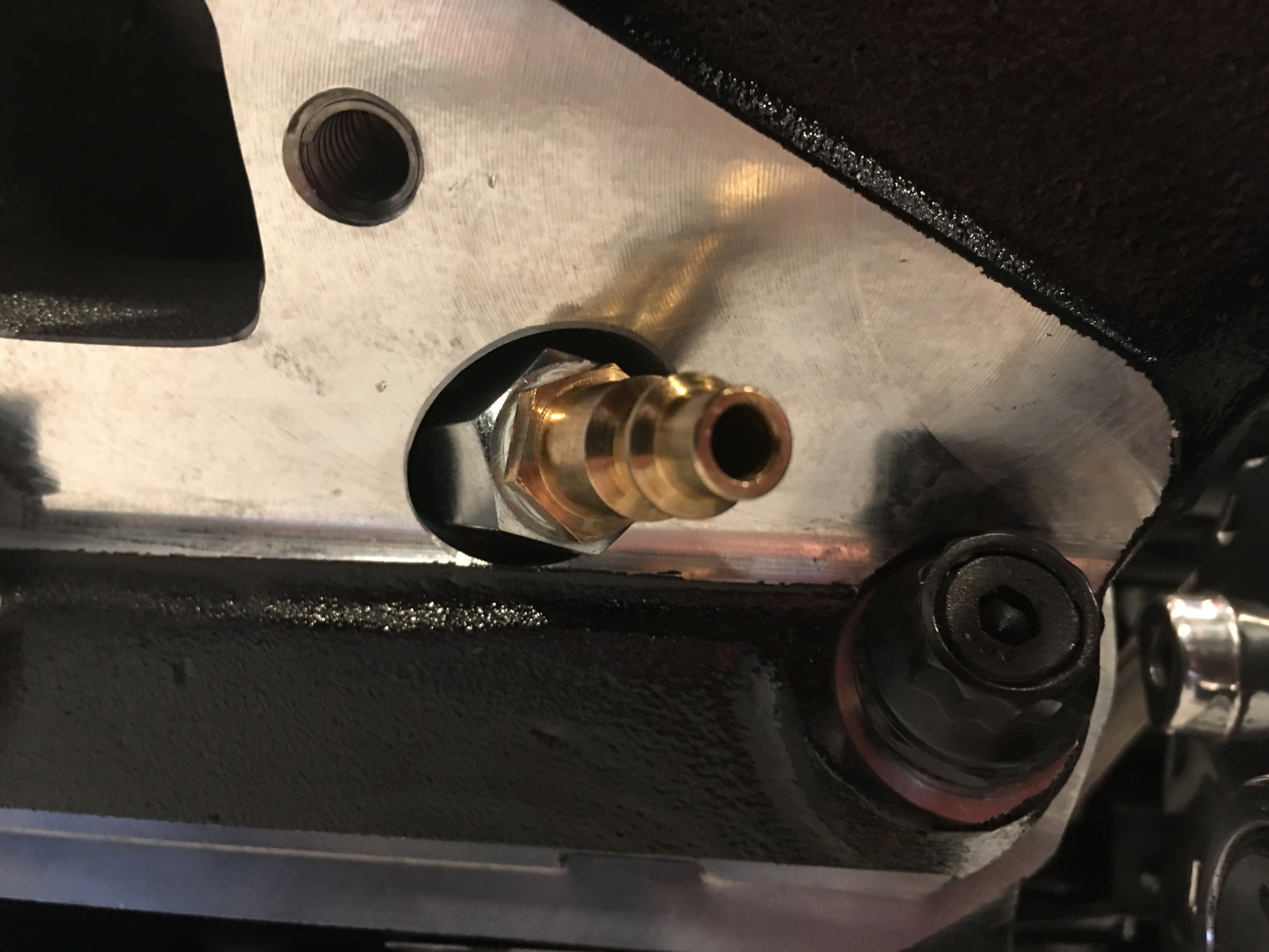
I’ve got a handful of details left to wrap up before we can run the engine at the dyno shop. First up, I needed to plumb the fuel filter between the fuel pump and the throttle body. I had a few scrap pieces of hose laying around from my airplane build, so I used one to insert the fuel filter into the supply line.

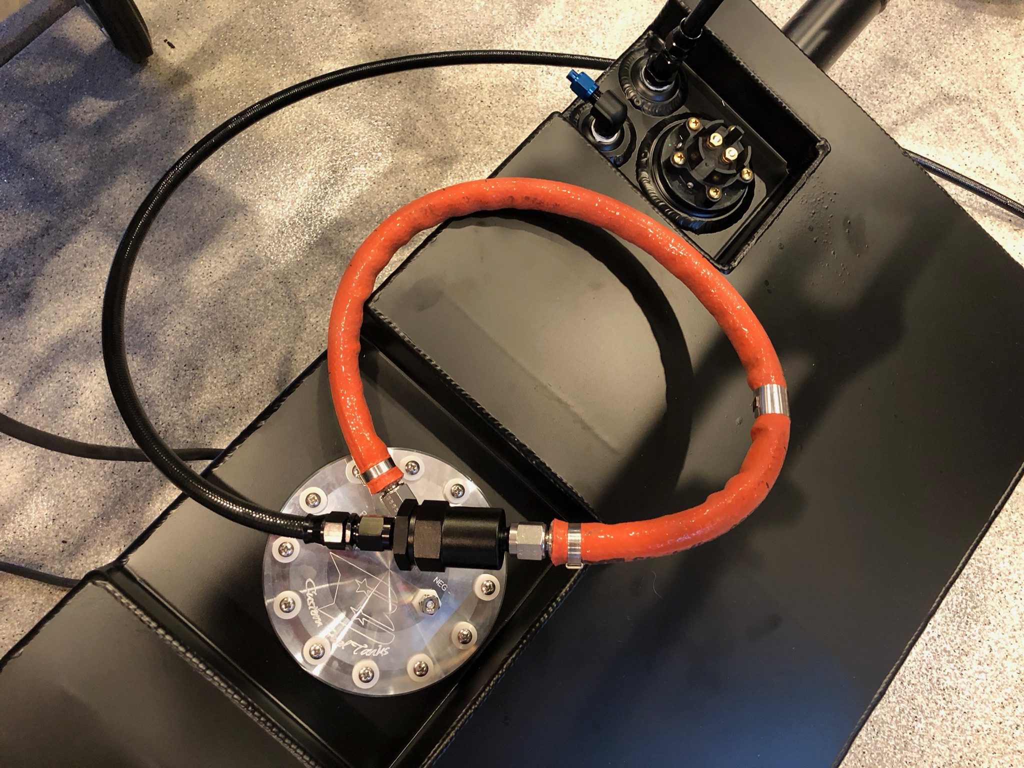
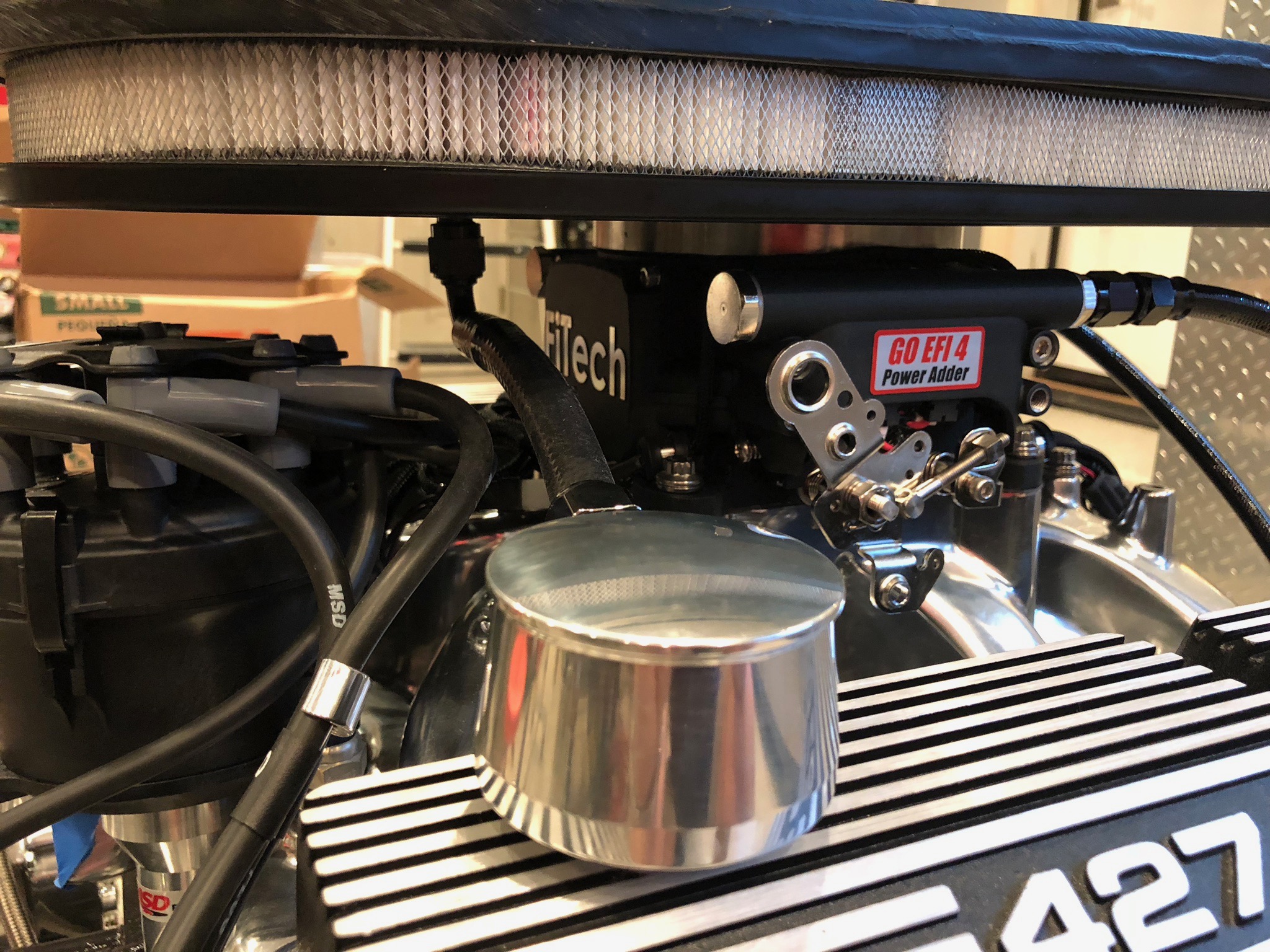
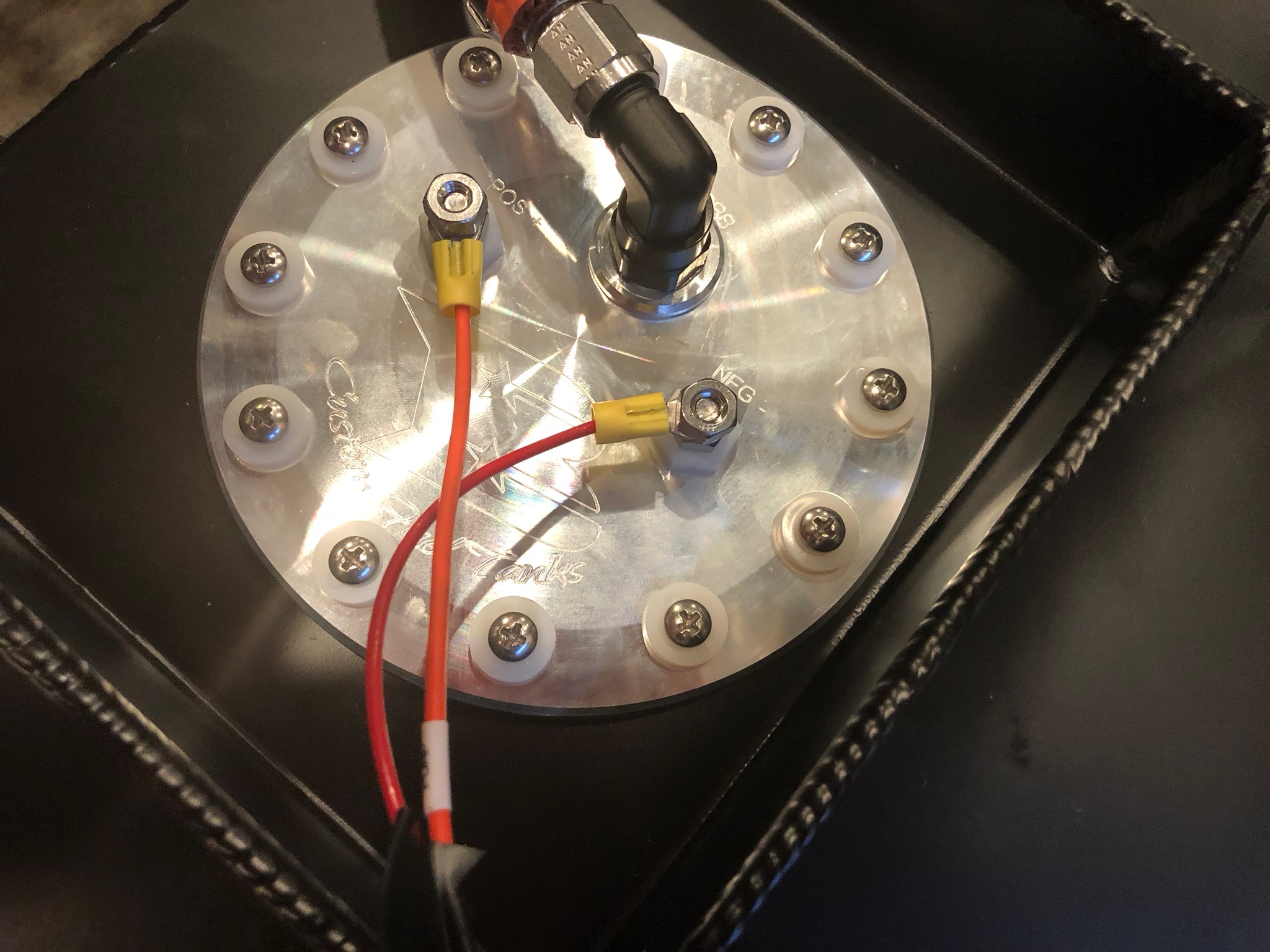
I also temporarily wired up the fuel pump to the FiTech unit. I’ll replace these terminals with better ones during the final wiring on the car, but this is what I had laying around that fit these large studs.

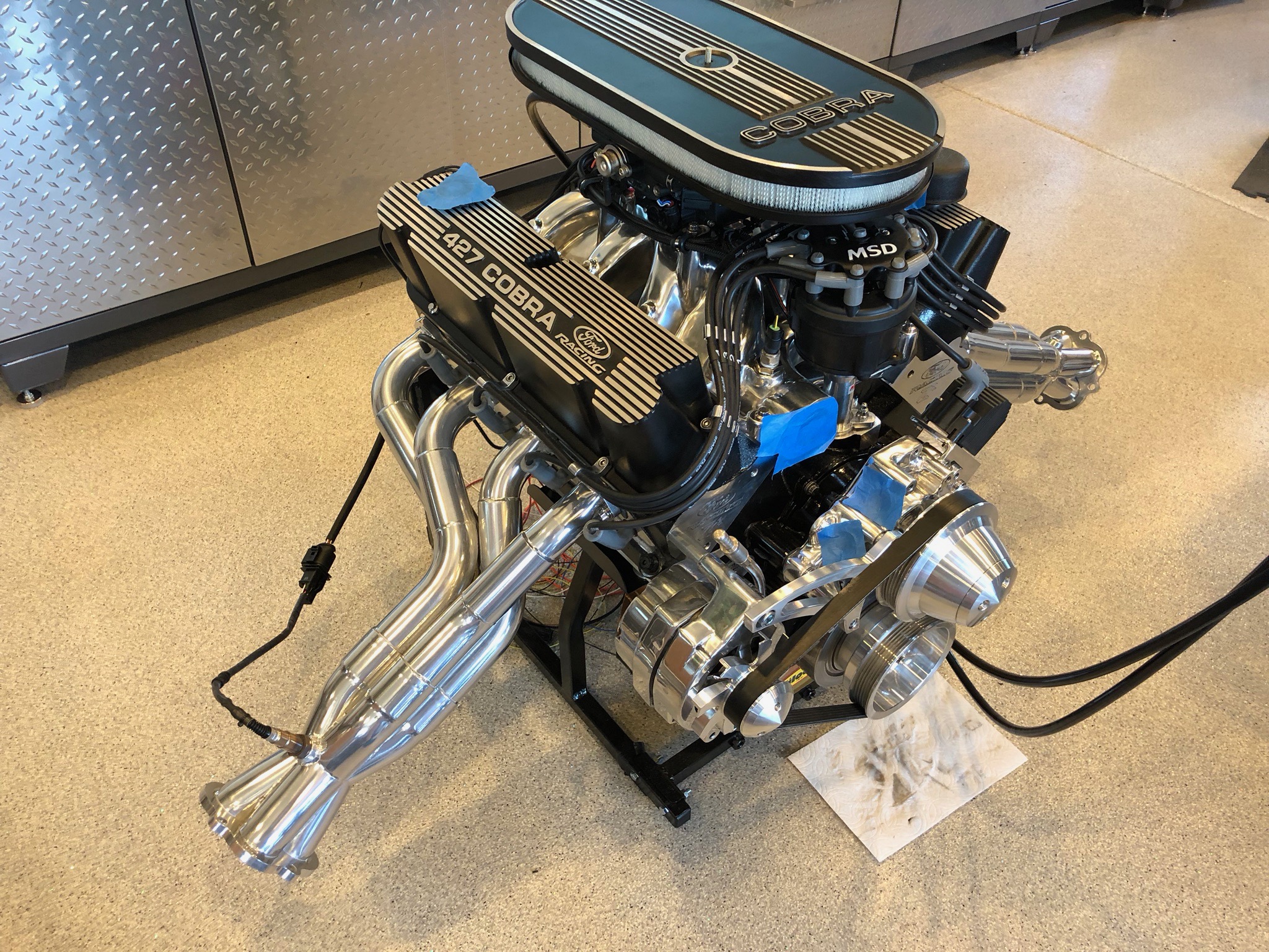
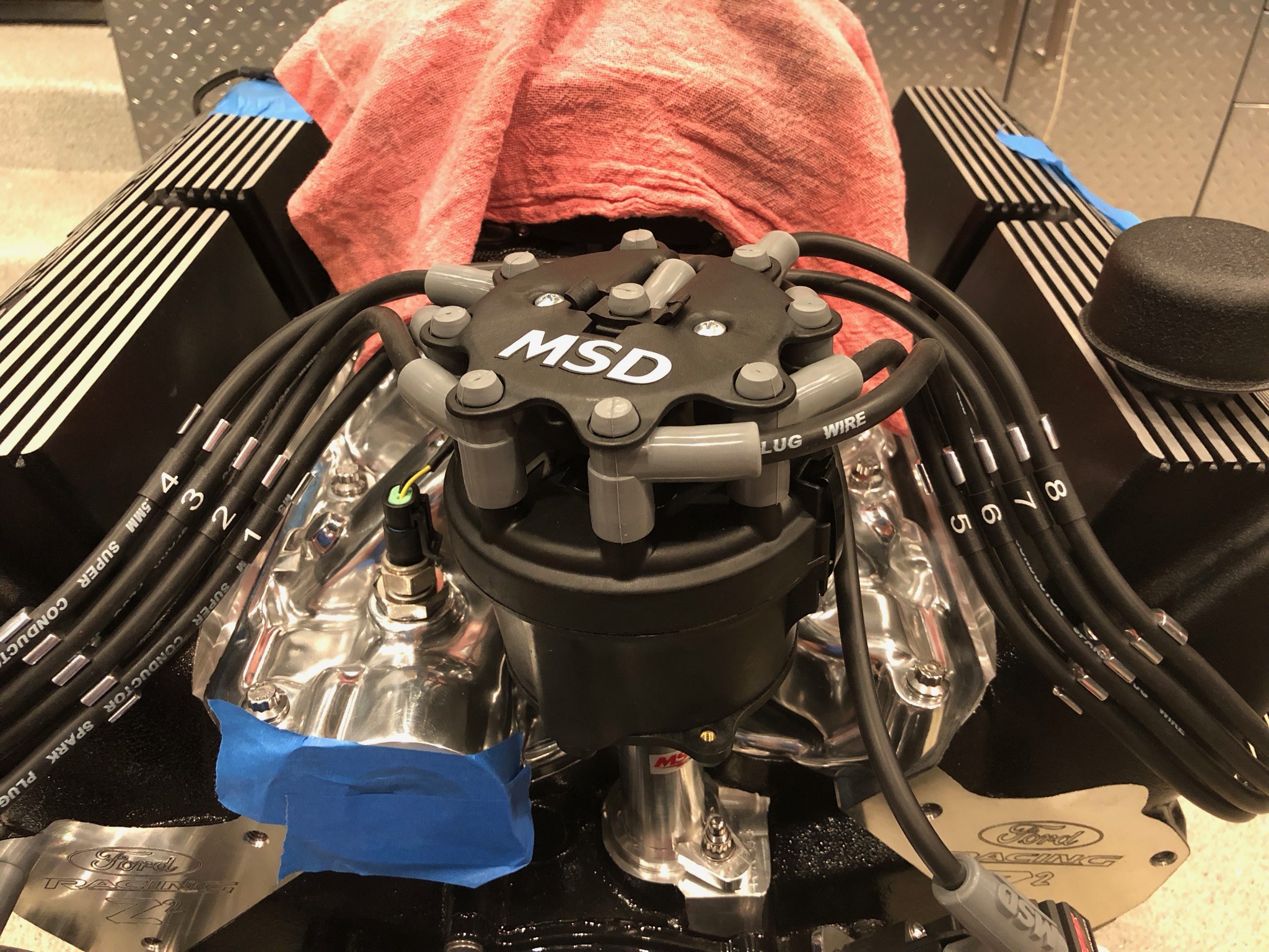
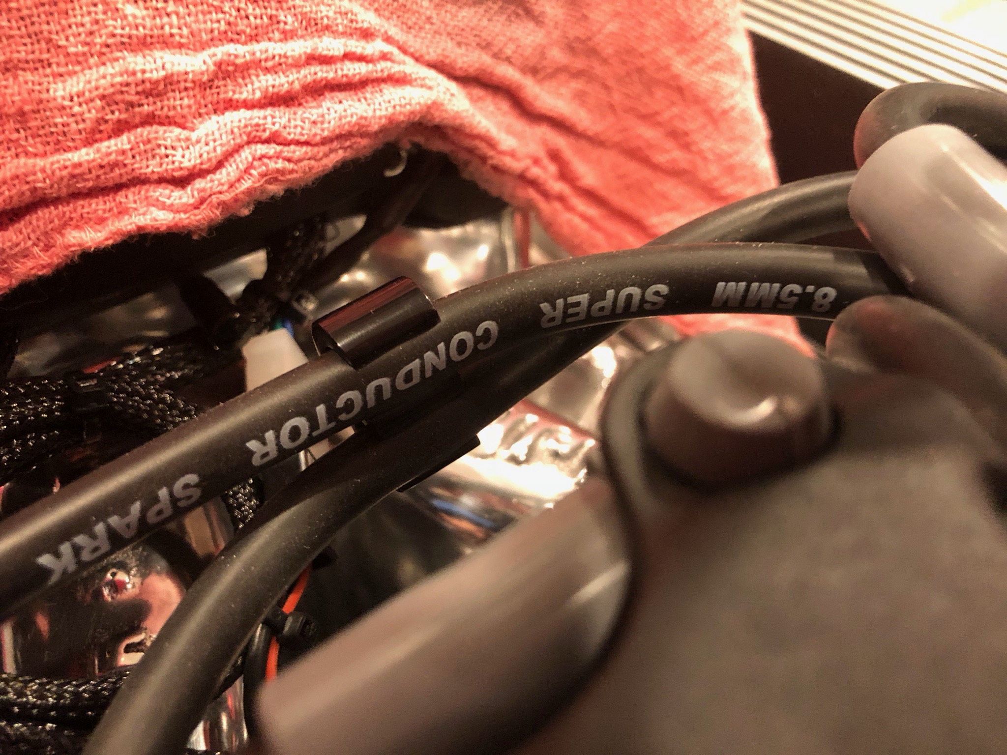
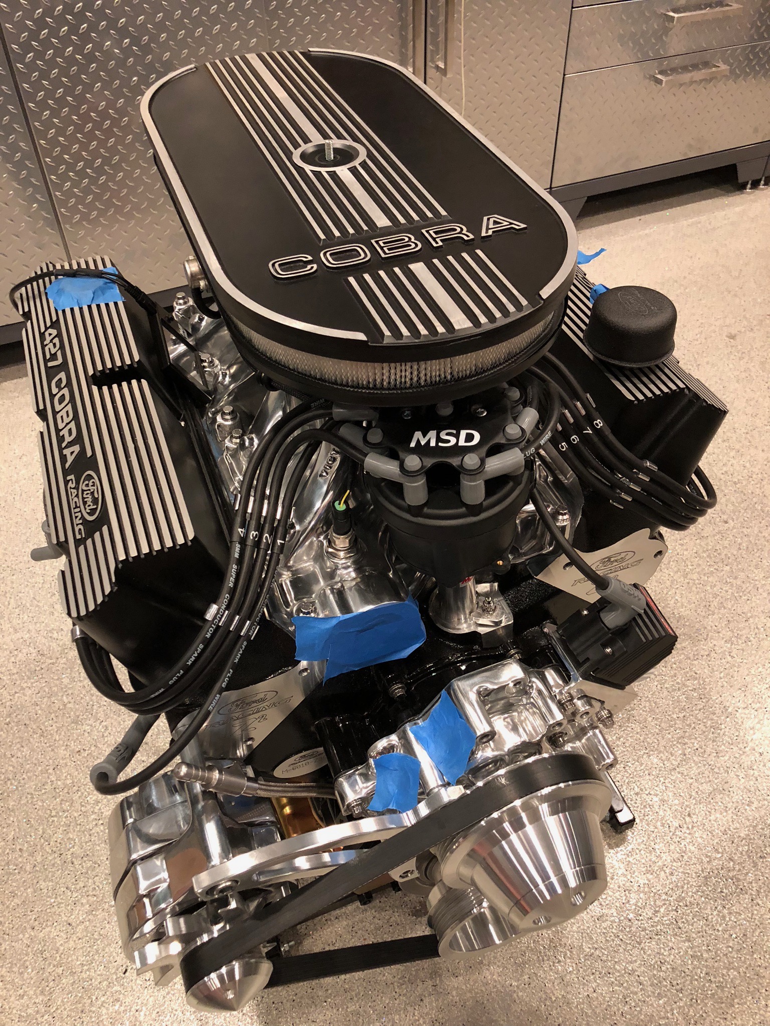
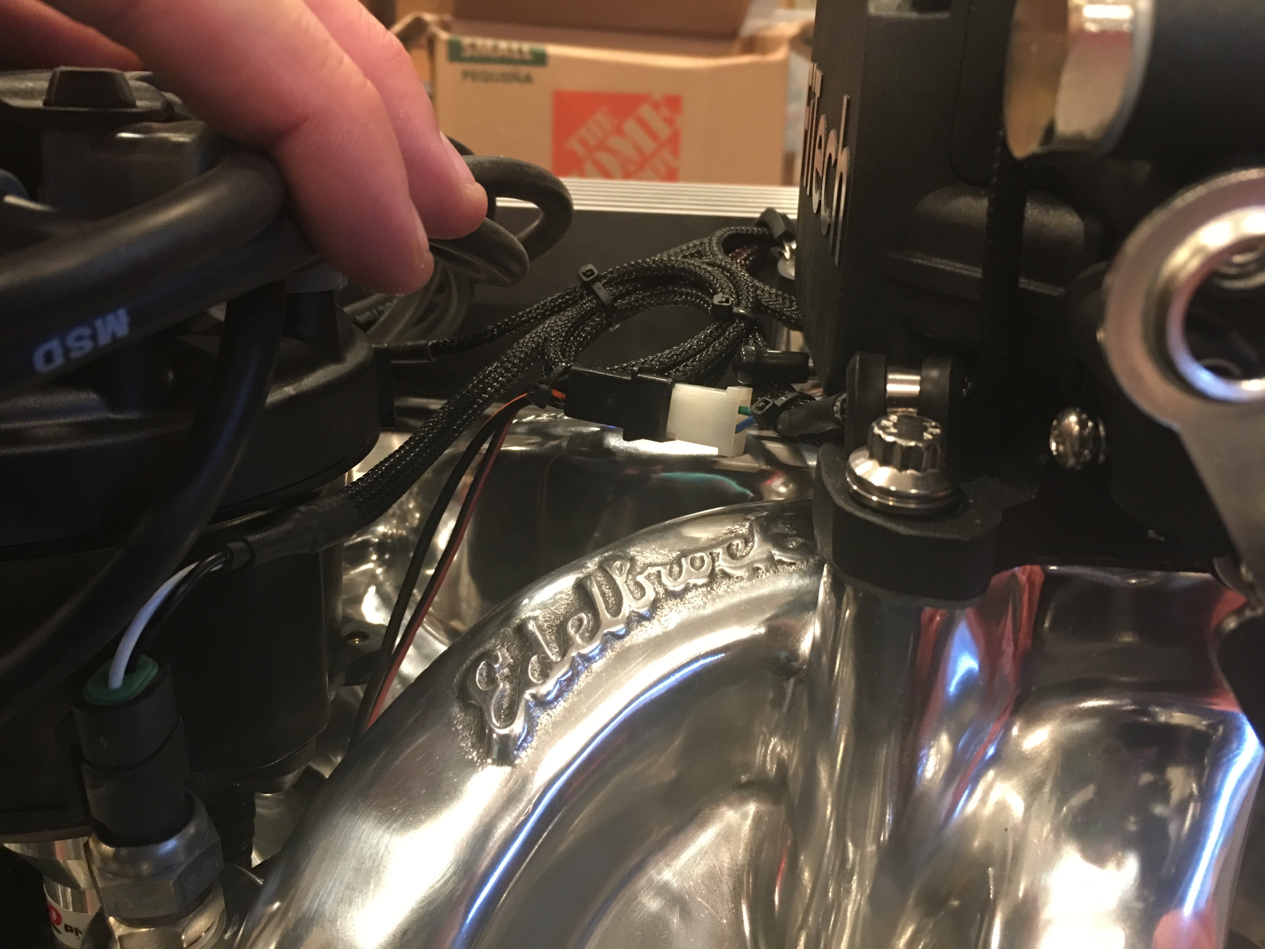
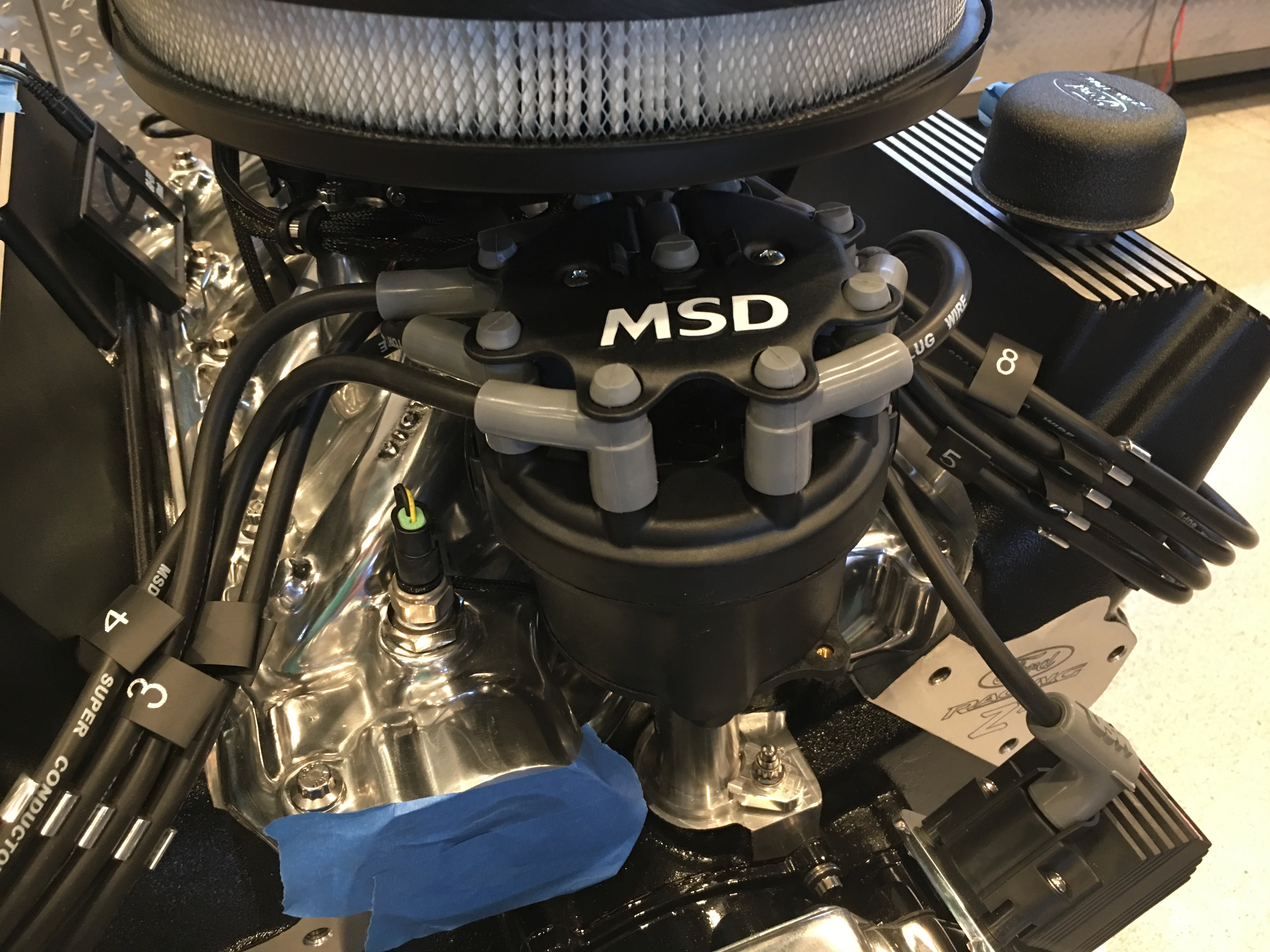
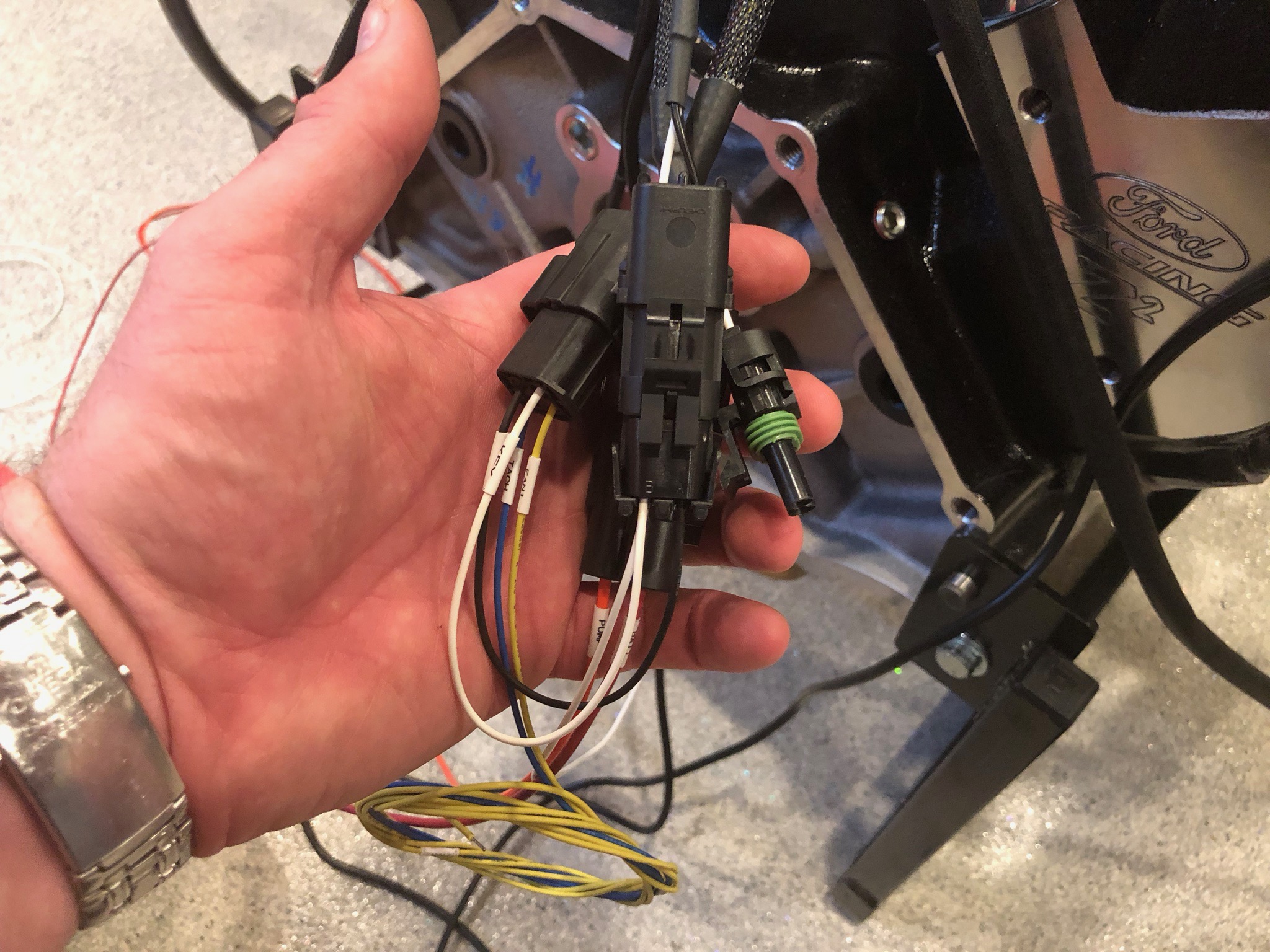
I also needed to wire up the ignition coil to the FiTech unit since it controls the ignition timing. Most of the car will be wired with automotive TXL insulated wire since that’s what comes in the Infinitybox wiring harness, but I don’t have any of that right now. I used some MIL-W-22759/16 wire I had laying around (which is better than the TXL wiring anyway). This cable snakes under the ignition coil (where it will be secured with a cushion clamp) and up behind the distributor where it follows the rest of the wires around the right side of the throttle body to the back of the engine.

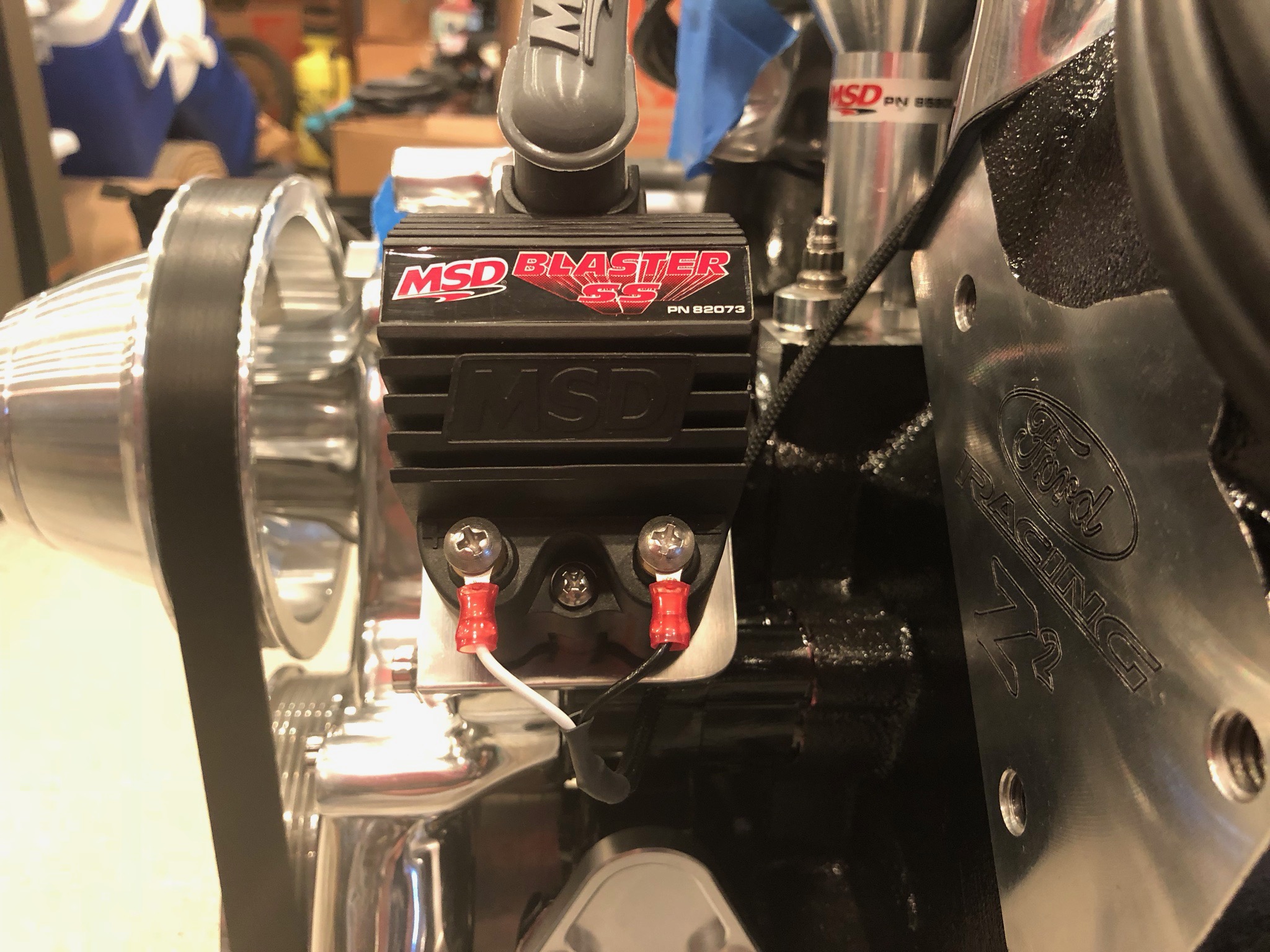
The coil needs to be connected to two wires coming off one of the other FiTech connectors, so I looped them back. The white wire will also be connected to the switched side of the ignition switch.

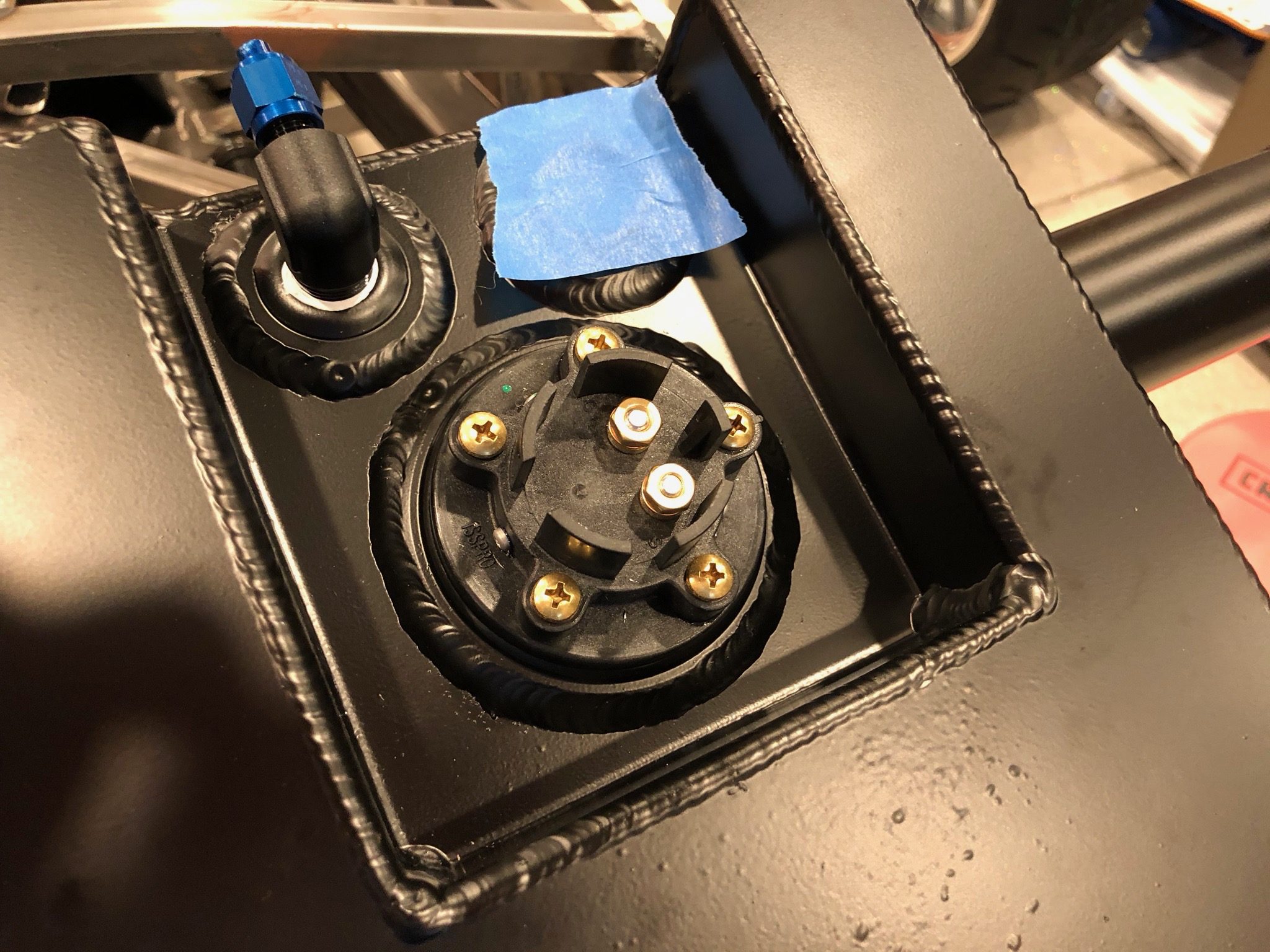
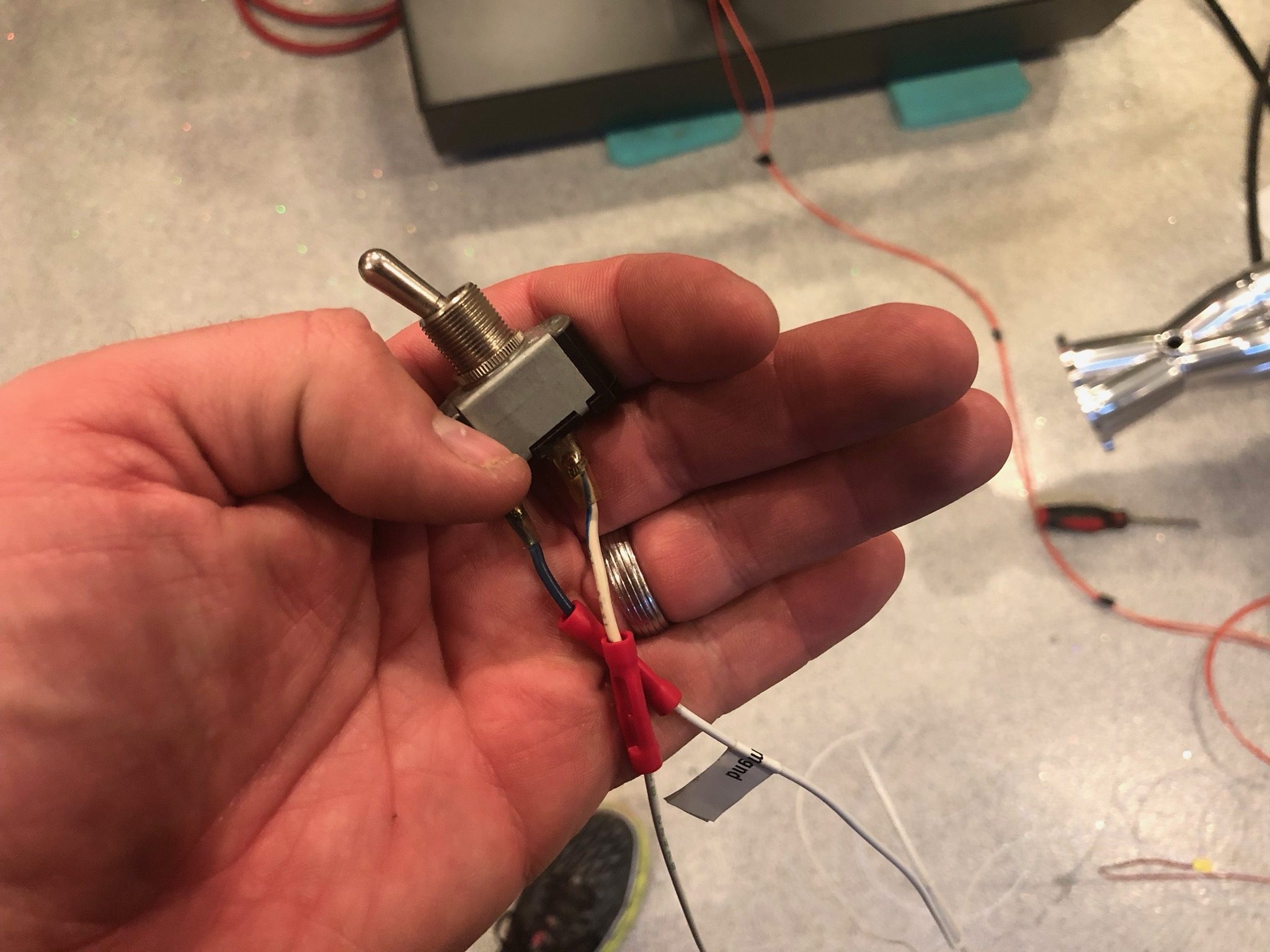
Since I don’t want to mess with the key switch now, I just rigged up an old toggle switch to turn the ignition on and off.

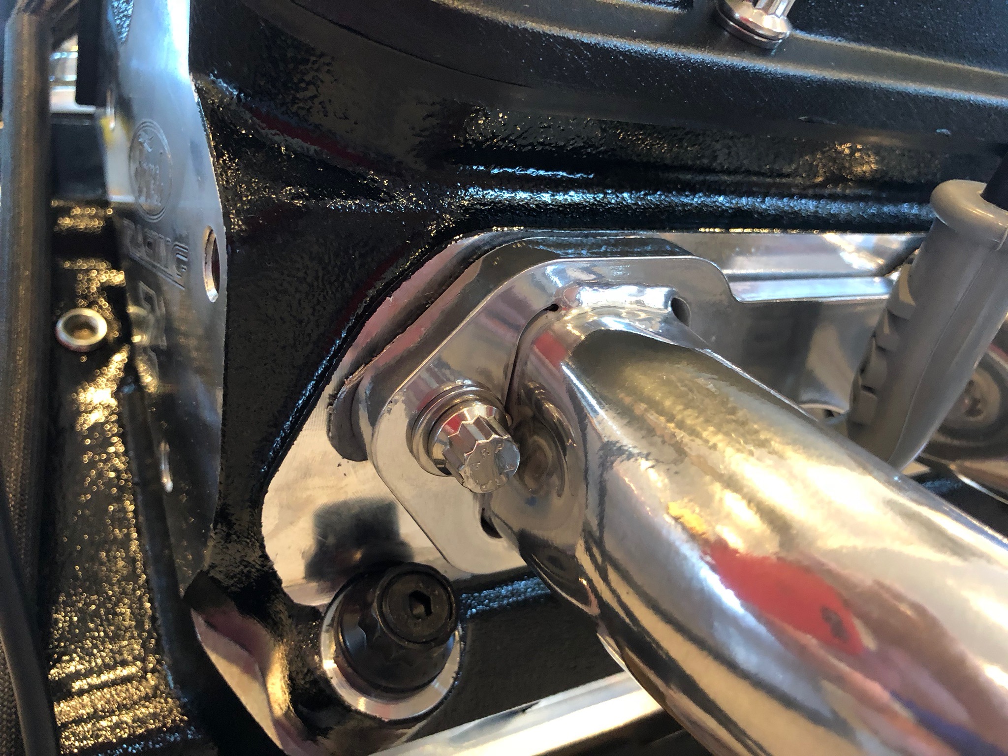
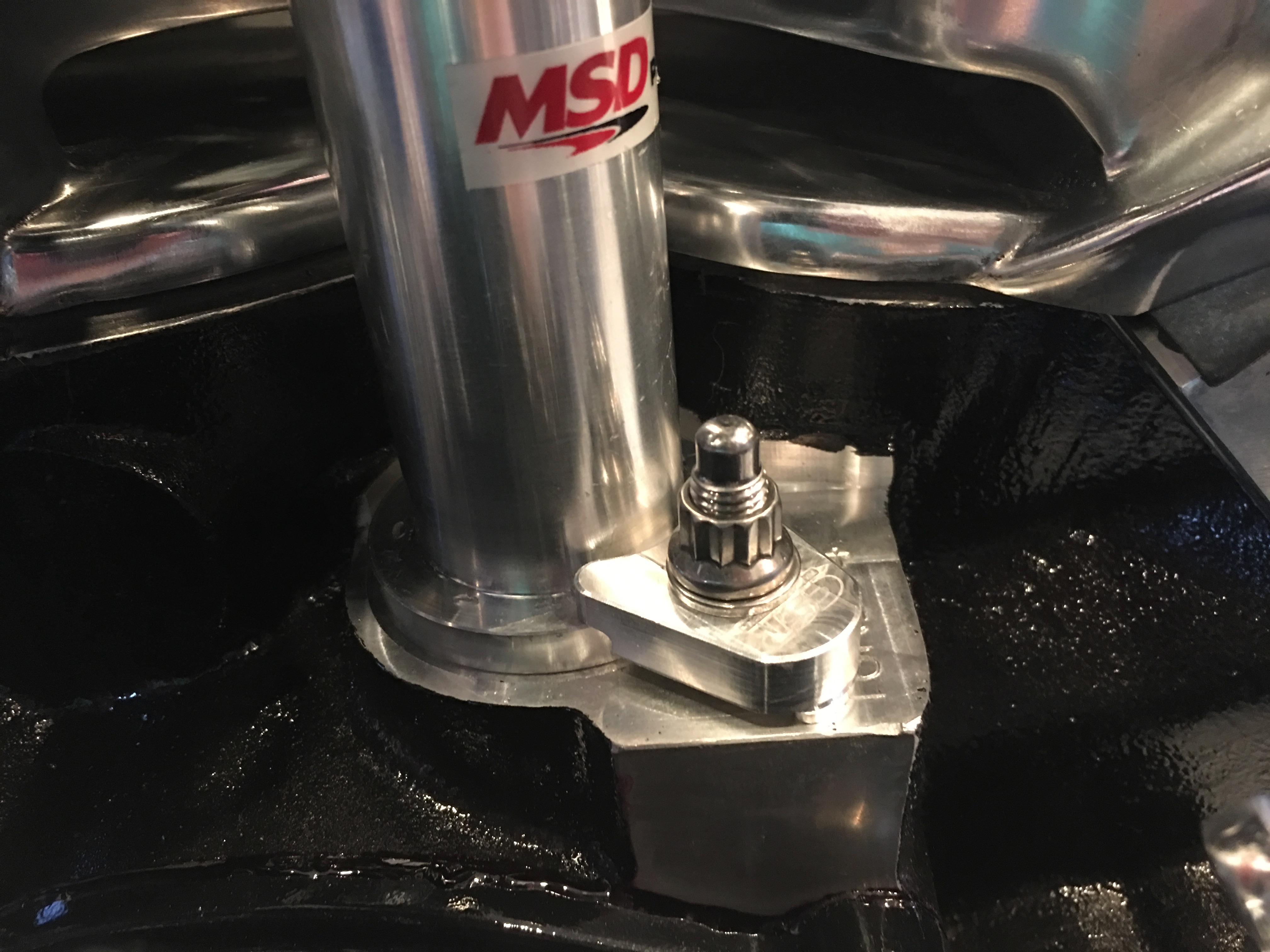
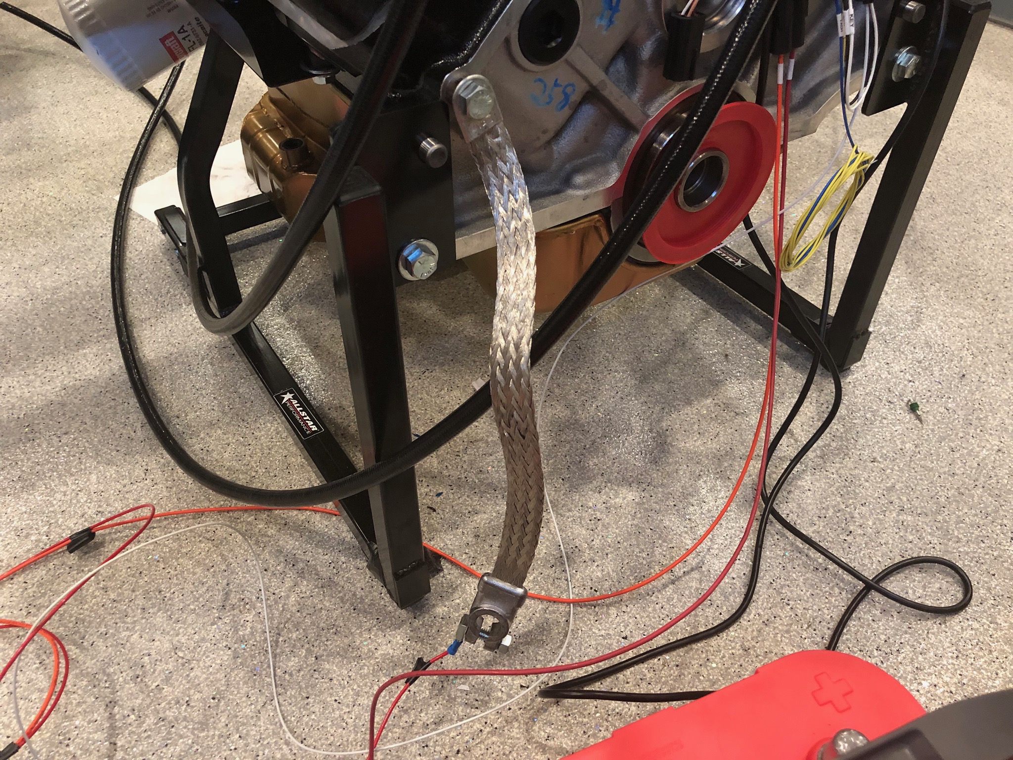
I also temporarily attached the ground strap to the engine block. At the other end is the red wire that goes to the fuel pump ground. I didn’t have any 18+ ga black wire around, so I used red and flagged it with some black electrical tape. None of this will end up in the car.

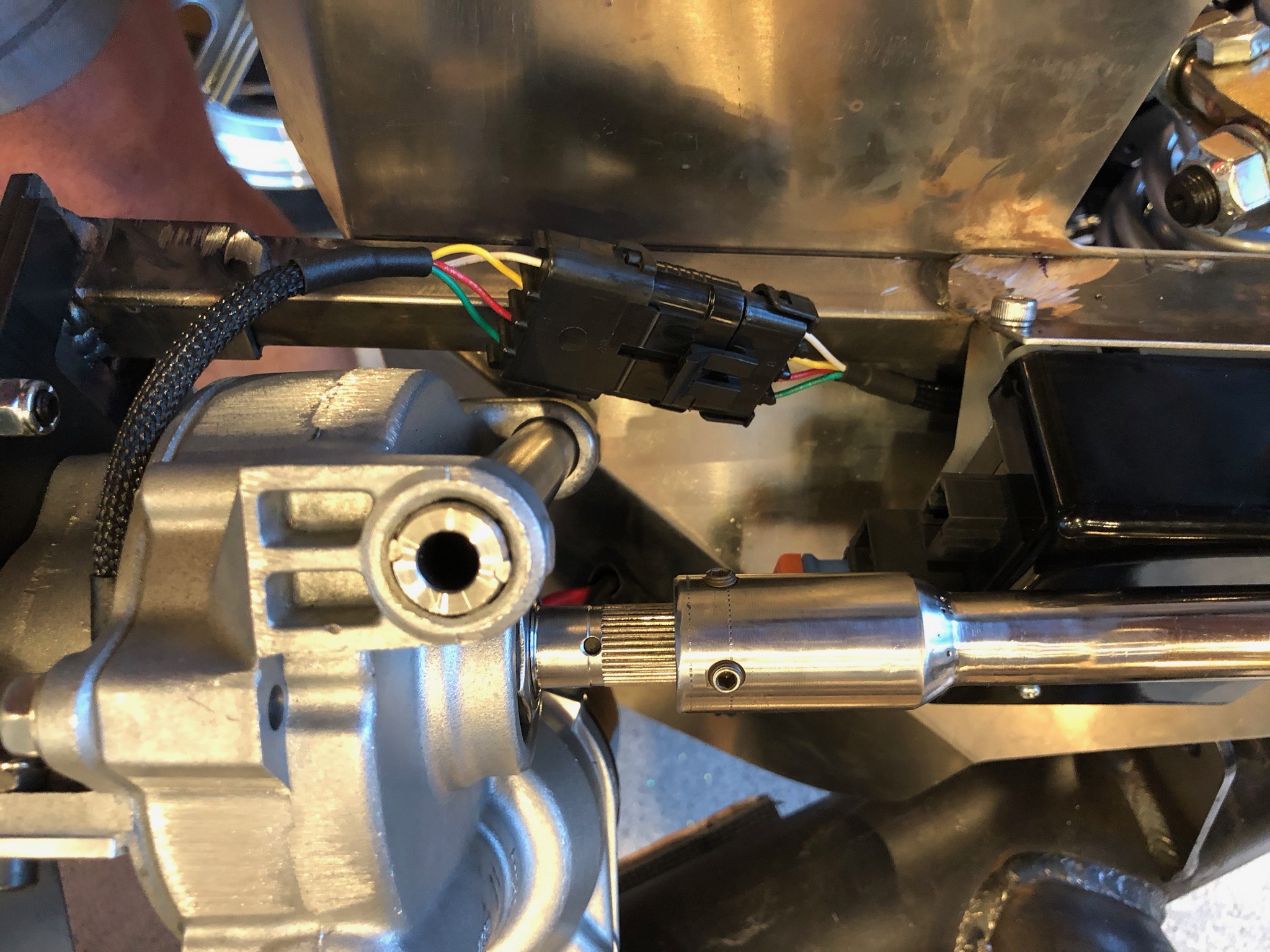
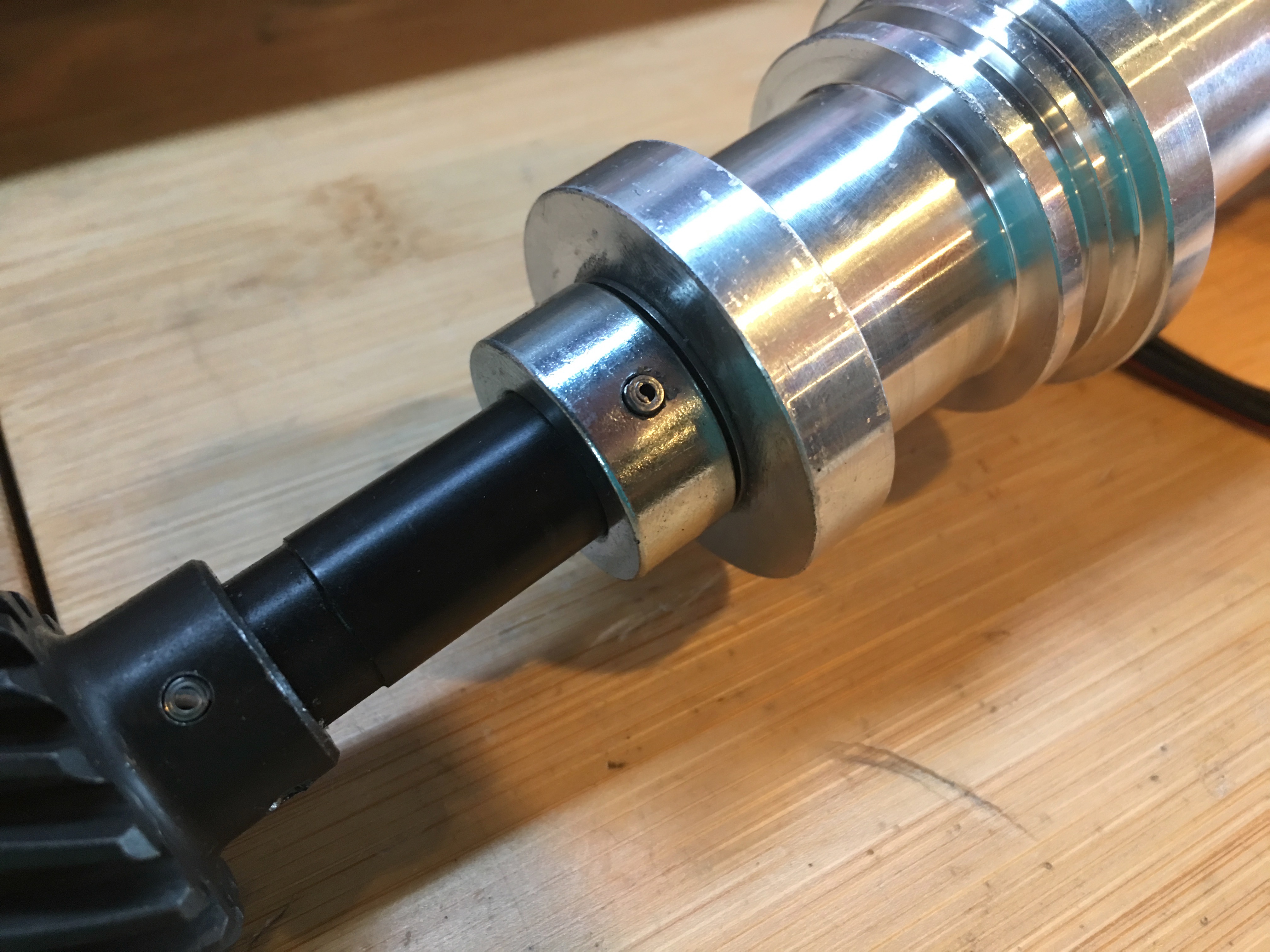
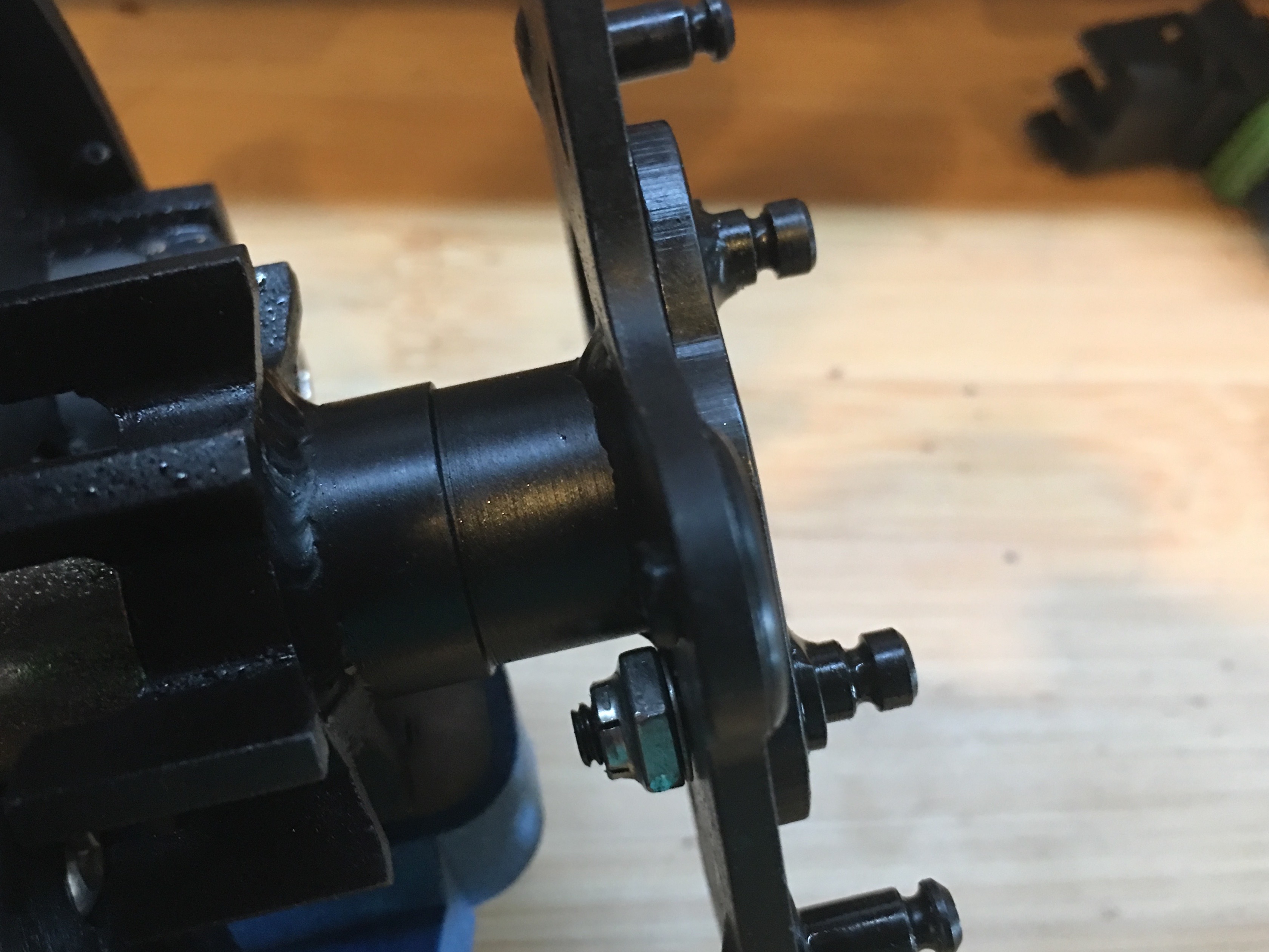
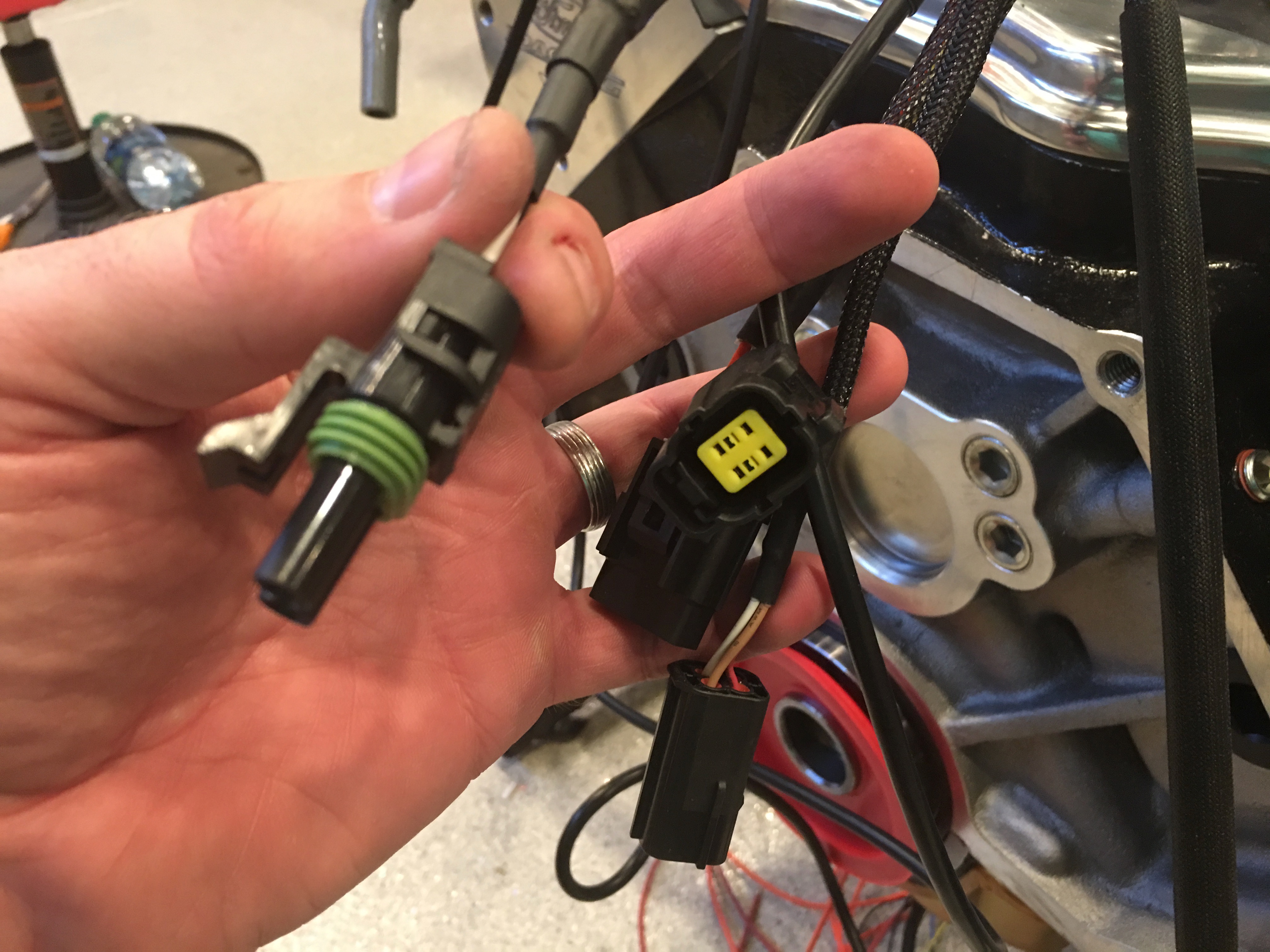
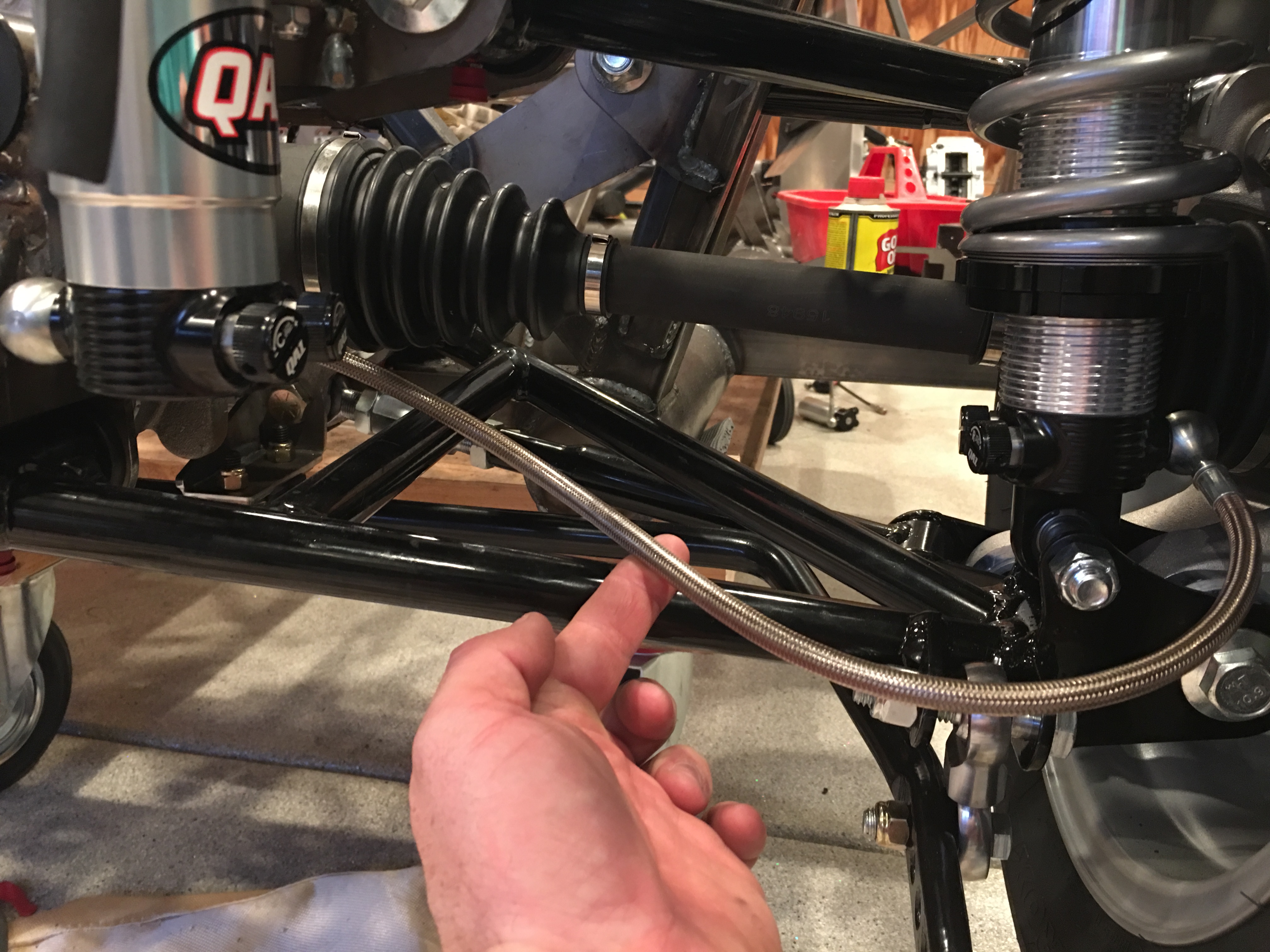
While I had my tools out to install the WeatherPak connectors on the back of the engine, I connected the electric power steering motor to the controller.

Started Fabricating Rear Brake Line

There will be a single hard line for the rear brakes coming along the left side of the chassis from one of the two brake master cylinders. It will tee somewhere on the left side and run to both rear brakes. I started by fabricating the hard line that will run from the left side of the chassis to the right brake fitting. It runs along the left, upper diagonal and across the aft edge of the reinforcing plate to the right, upper diagonal. It then drops down the right, aft diff support before turning forward to reach the fitting.

Here’s a view from the front side of that fitting looking aft. I haven’t added any clamps to this  tubing yet, but it will not touch any part of the chassis when I do.

Installed PCV Valve

I received the M/E Wagner PCV valve in the mail today. I cut a couple of pieces of the silicone hose and had it installed in just a few minutes.

The inlet on the bottom of the unit is aligned with the breather cap and the outlet on the side is aligned with the nipple on the throttle body.

The adjustment screws will be easy to reach from the left side of the engine by reaching under the air cleaner. Getting to the calibration port may be a little more challenging as it’s basically on the bottom of the unit. Although these hoses are under vacuum, I will probably add some worm clamps to them.

Engine Breather

The valve covers came with a Ford Racing breather cap, but we want to have a matching breather cap on one valve cover and PCV valve on the other. This also has a weird, crinkle finish on it that doesn’t match anything else on the engine.

Billet Specialties sells these really nice PCV valves that fit in the 1.25″ valve cover holes. My plan was to remove the PCV valve from one of them and use it as a breather, but a friend of mine recommended an M/E Wagner adjustable PCV valve, so I’m going to pull the PCV valve from both of them.

After unscrewing the base, the PCV valve can easily be removed with a pair of snap ring pliers.

I fit a piece of silicone hose with chrome fitting on the end and installed it in the valve cover.

The breather needs to have access to a filtered air supply, so I drilled a 9/16″ hole in the air cleaner base.

In the hole, I installed a straight bulkhead fitting and a 90º hose adapter.

It’s is a pretty straight shot from the breather to the hose fitting. When the M/E Wagner PCV valve arrives, I’ll plumb it inline between the other cap and the throttle body.

Fabricated Temporary Fuel Hoses

In preparation for running the engine at the dyno shop, I fabricated a couple of hoses. I’m using Fragola stainless steel reinforced conductive PTFE hoses with a black nylon covering. For the dyno run, I just need a supply and return hose, so I cut the 20′ hose in half and installed straight fittings on each end.

Here’s where the supply and return lines attach to the back of the throttle body.

We also received our headers from GP Headers. These are ceramic-coated, stainless steel headers with double collectors so that the O2 sensor can be installed in the engine compartment.

These are really beautiful, especially compared with the ones from FFR. I installed the FiTech O2 sensor in the right side bung since the passenger side of the engine compartment is much less crowded.

The GP Headers have a much thicker flange (3/8″ vs 1/4″), so the 3/4″ bolts that came with the engine bolt kit aren’t long enough. There is only about 1/4″ of thread engagement in the block with these bolts, so I’m going to see if ARP will exchange these for 1″ bolts.

Finished up Distributor Wiring and Fuel Pump Installation

I received a new order from Summit Racing with some additional wire separators.

I used one on each side to keep the wires organized as they make their way up to the distributor. After installing the wire separators, I slid the heat-shrink wire labels in place and shrunk them down.

Here’s the other side.

I used a two-conductor wire separator behind the distributor to tie the #4 and #7 wires together. For some reason, they didn’t stock polished, two-conductor separators on Summit, so I ordered black anodized ones. This will largely be hidden under the air cleaner though, so I think black will be just fine. I can always sand off the anodizing and polish it if it’s too visible.

Here’s a shot of the whole engine with the distributor wiring all wrapped up. Only a few remaining details to wrap up before I can get the engine to the dyno shop.

I also received and installed the Classic Instruments tube type fuel level sender. This is a 0-90Ω sender that is compatible with the gauges from FFR. The tank is 10.75″ deep here, but this sender is only 10″ long below the flange. That leaves 3/4″ of unmeasurable fuel below the sender; given the taper of the bottom of the tank, that’s probably only 1-2 gallons of fuel. I’m fine  with a 1-2 gallon fuel reserve below the empty reading on the fuel gauge.

Installed Distributor

The FiTech EFI system controls the ignition advance, so the mechanical advance has to be locked out. I started by removing the springs and weights.

The roll pin on the retaining sleeve has to be driven out so that the shaft can be pushed up in the distributor.

With the shaft pushed up, it can be rotated 180º so that the advance stop bushing pin can be dropped into a hole in the advance plate which locks the two pieces together. Afterward, the retaining sleeve can be slid back in place and the roll pin reinstalled. Now there are no moving parts in the distributor (other than the shaft and rotor).

In order to install the distributor in the engine, I needed to reset the engine to 12º BTDC on the compression stroke of the #1 engine. I installed the air fitting in the #1 cylinder so that I could tell when it was on the compression stroke.

I rotated the engine until it was 12º BTDC.

I then stabbed the distributor into the block. I needed to adjust the oil pump driveshaft a couple of times until the distributor dropped into place.

I then installed the distributor hold down clamp to lock the distributor in place.

The cable from the FiTech unit leaves a bit to be desired. The cable is surprisingly short and for some reason comes out of the back of the unit. Without extended the wires, it really can only run around the left side of the throttle body or over the top. There is no way to run around the side without interfering with the throttle linkage, so I run the cable over the top. I really don’t know why FiTech doesn’t have this cable coming out of the front of the unit to avoid this problem.

On the right, you can see the distributor control cable coming down from the top of the unit and secured with an Adel clamp to prevent it from moving. I pulled the coolant temperature cable out from underneath the intake runners and coiled up the extra on the front of the throttle body. I also installed the secondary coolant temperature cable that connects to the dash gauge. Since we’re installing a fairly long air cleaner, virtually all of this wiring will be somewhat hidden.

I also cut the cable going to the coolant temperature gauge and installed a weatherpak connector at roughly the same position as the other connectors. I want to easily be able to disconnect the engine from the car without having to pull wires through the chassis.

I cut all of the ignition wires to length and crimped terminals on them. I still need to order a couple of wire separators to neaten the wires up a bit and then I can shrink the wire labels onto the wires.

Powder Coated Fuel Tank

We’re going to need the fuel tank for the engine dyno run since the dyno shop is not set up to run EFI engines. The simplest solution is to bring my own tank and let the FiTech unit drive the integrated pump. Before I put fuel in the tank though, I need to get it powder coated since I wouldn’t want to put a tank with fuel vapors in the powder coating oven.

I pulled the fuel pump so that I just have the bare tank and then used some scotchbrite pads to rough up the surface to give the powder coating a better grip. After cleaning the tank thoroughly with solvent, I hung it from a couple of the trolleys in the loading rack.

After giving it a thorough coating of powder, I transferred it into the oven.

After 30 minutes or so at 400ºF, I transferred it back to the loading rack and set it in front of the exhaust racks to get some cooling airflow.

After bringing it home, I reinstalled the fuel pump and fuel outlet fitting.

I also installed the fuel vent fitting and capped it until I am ready to hook it up.

I purchased a 90º angle for the fuel return, but unfortunately it won’t work since Boyd put the boss too close to the side wall of the recess. A straight fitting would obviously thread in fine, but I think it would push the hose up too high since the top of the tank will only sit 3/4″ below the trunk floor. I’ll have to figure out another solution here.

Rear Brake Flex Lines

I installed the fittings in the rear brake calipers with some high-temp thread sealant and then spent some time determining where to mount the tab that holds the fitting the other end of the hose screws into. It needs to be in a location that won’t cause the hose to rub on anything as the wheel moves up and down and also provides a convenient location for the hard lines that connect to the other side of the fitting.

I ended up deciding to weld the tabs on the front side of the mount for the rear side of the upper control arm (the other side of the mount from where the remote reservoir is mounted).

Here’s a shot looking backward toward the front side of this mount. The tab is welded flush with the face you see here. The hard line will curve immediately upward from here (to miss the CV joint boot) and follow that angled tubing upward to a point where the hard line can cross to the other side of the car.

Mounted Rear Strut Reservoirs

I welded on the mounting brackets for the rear strut reservoirs. I ended up deciding to mount them to the side of the upper rear control arm mounting bracket. This puts it well out of the way of any moving parts and provides nice routing for the hose that connects the strut to the reservoir.

The hose follows an ‘S’ curve from the strut to the reservoir. I’ll anchor it to the lower control arm near the middle with a couple of adel clamps so that it can’t rub on anything.