The buttons in the button panel I showed yesterday have LED rings around them that will light up when the corresponding function is turned on. Most of these are pretty simple since there is a single output wire from the front POWERCELL for each of the functions. I tapped into each of these wires and will power these LEDs from them.
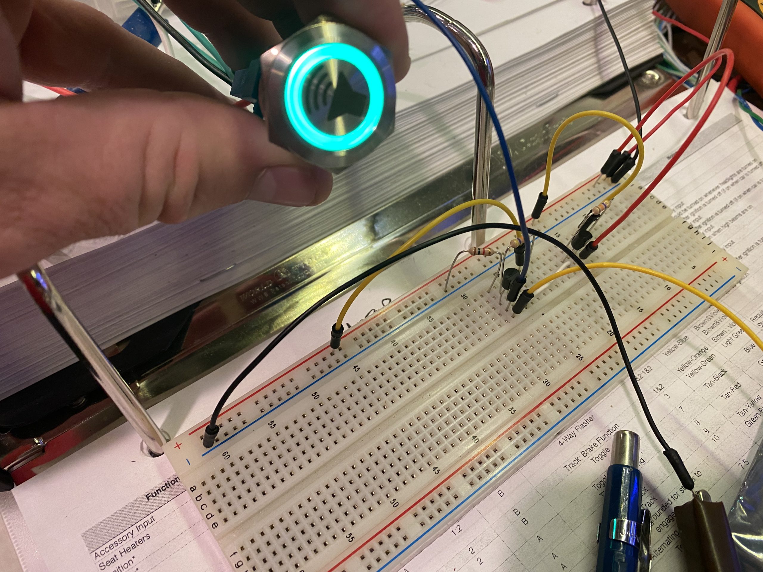
The hazards are a different matter though. There’s not a separate output from the POWERCELL for the hazard lights. Instead, the power cell flashes both left and right turn signals in unison. I obviously don’t want the hazard button to flash whenever a turn signal is on; it should only turn on when both turn signals are on at the same time. Essentially, I need an AND gate for 12V signals that is capable of flowing enough current to drive these LEDs.
Fortunately, that’s a pretty trivial circuit to build with a couple of NPN transistors and a few resistors. The two upper yellow wires represent the left and right turn signal wires. When both are plugged in to the power rail adjacent to the red line, the LEDs turn on, but if either wire is removed from 12V (as would happen if only a single turn signal is turned on), the LED is off.
I have some small breadboards coming in a couple of days and will solder up this circuit to be installed in the car.