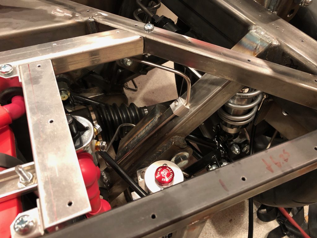
Wrapped Up Brake Line Installation

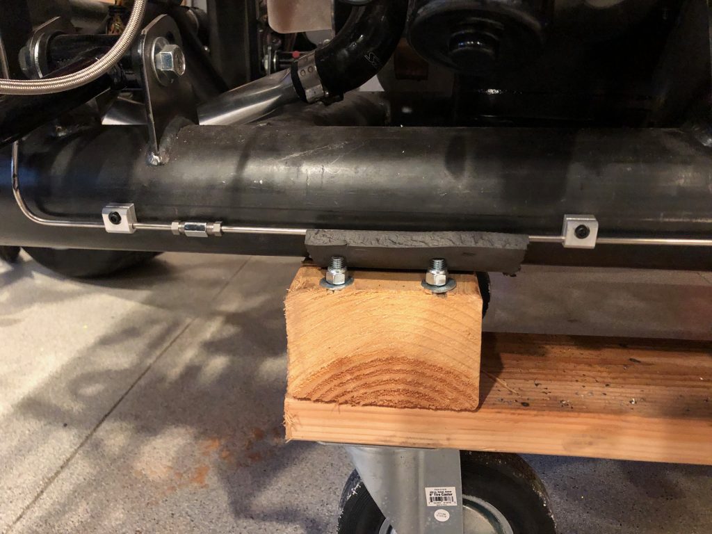
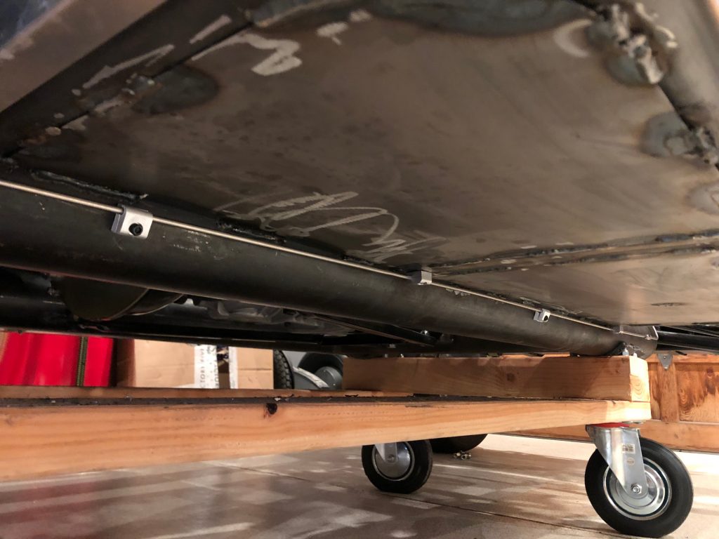
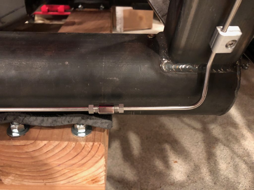
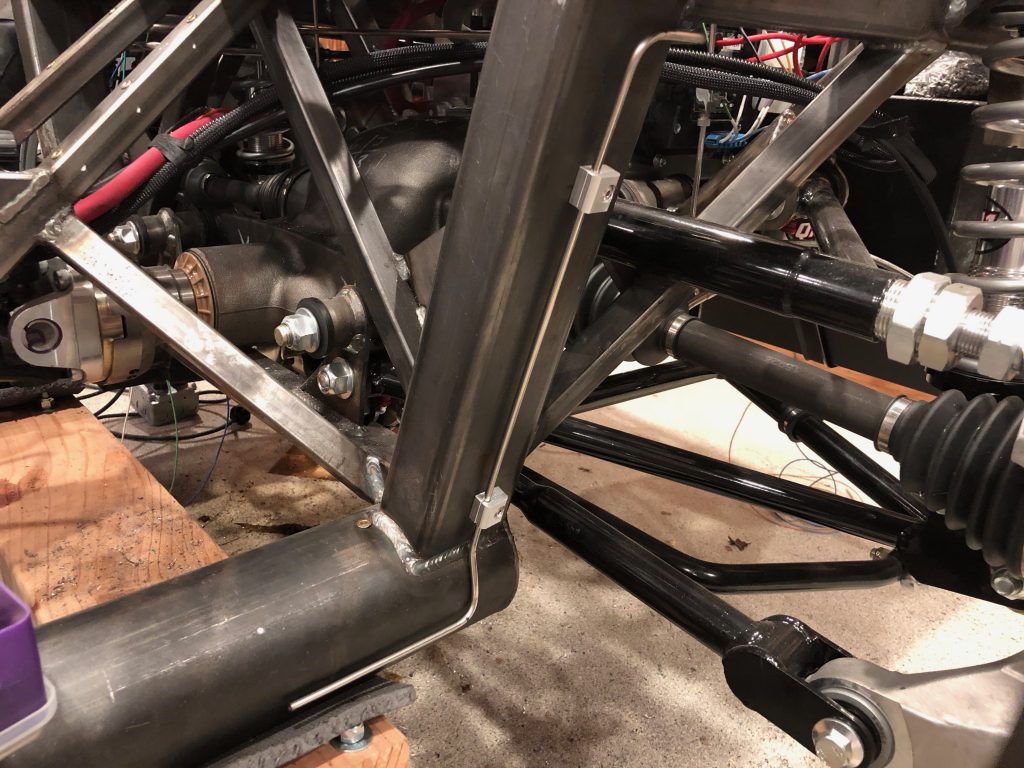
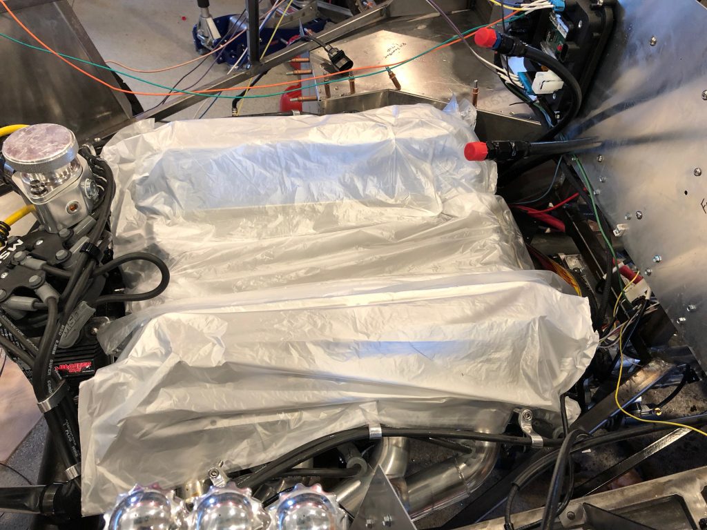
I laid out and installed all of the brake line supports for the long, straight run along the 4″ chassis tubing. There are four of the mounts with the curved back mounted directly the the 4″ chassis tube.

There are also a couple of mounts attached to the underside of the square tubing under the seat. I didn’t realize until after I took this picture that I had intended to install the spiral brake line guard before flaring the ends. I’ll have to see if the tubing is long enough to remove one of the flares and install the guard. I’d really hate to have to remake the brake line.

After torquing all of the fittings, I filled the fluid reservoirs and started trying to bleed the brakes. I still have more work to do to get all the air out of the system.

Started Fabricating Rear Brake Line

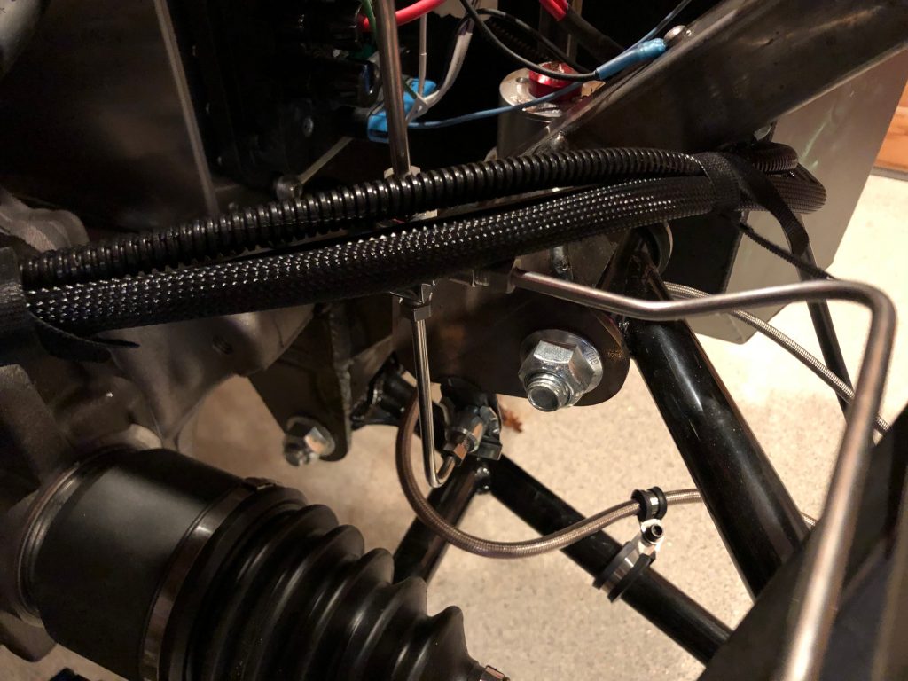
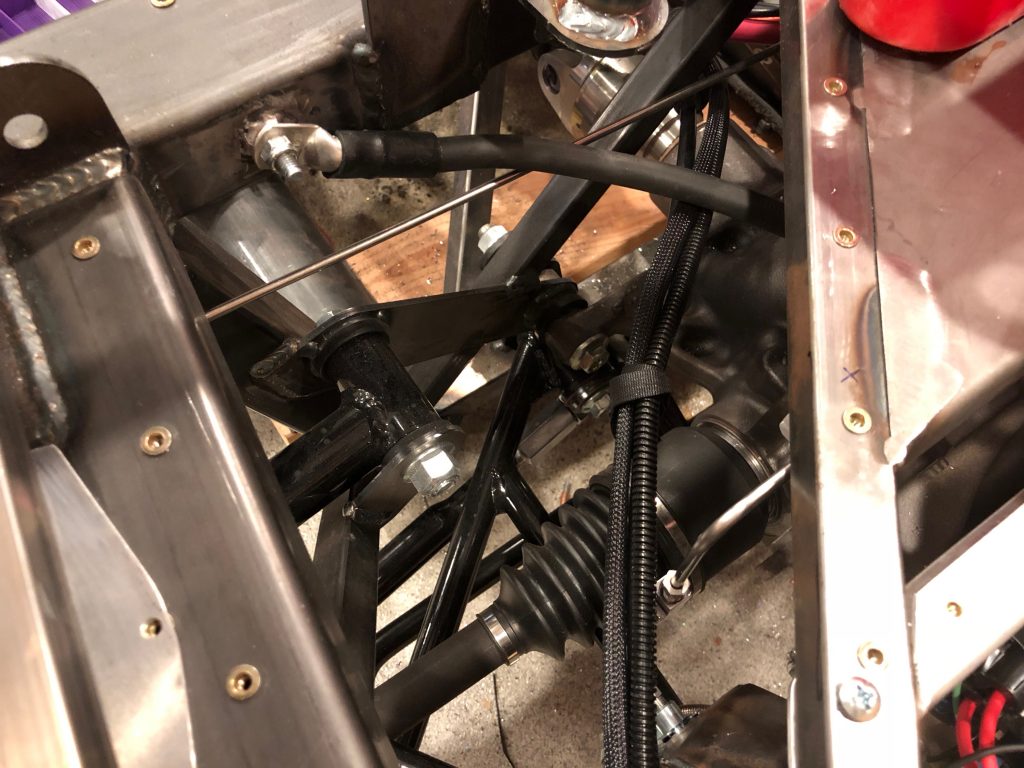
I started fabricating the rear brake line that transitions from the left 4″ chassis tube up to the tee on the left side of the chassis. If I use this piece, I’ll need to install a separate straight section from here forward to the other piece I installed here. I have a long enough piece of tubing remaining that I could make a single piece that runs from the tee forward to the other piece. It would let me avoid an extra union in the line which would reduce the chance of leaks, but it would be trickier to make a piece that long.

The tube still needs to be bent to run back along the rectangular tubing and then over to the tee near the bottom of the picture.

Wiring Connectors and Rear Brake Line

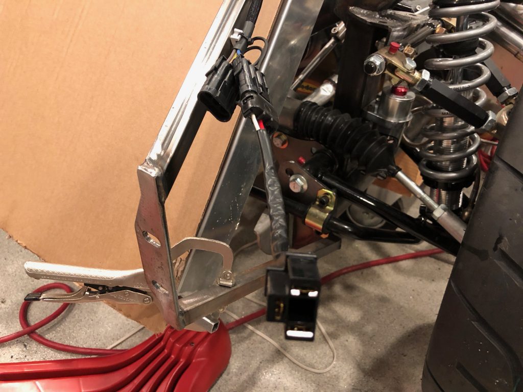
My order of Weather Pack connectors showed up, so I installed the remaining ones that were missing. For the headlights, I also fabricated short jumper cables to the plug that attaches to the back of the bulb. When I switch to LED bulbs, they might have a different connector on the back, so it will be trivial to fabricate a different jumper if necessary.

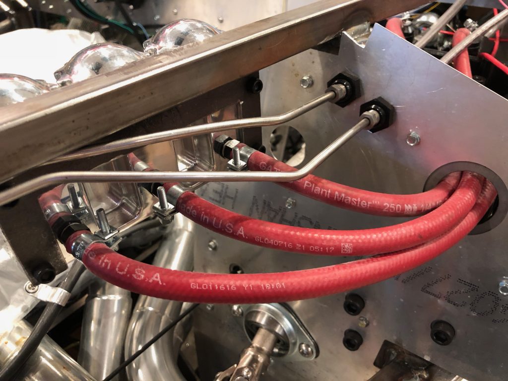
I also got started on the rear brake line. This line runs from the forward side of the pilot’s footbox, along the upper 3/4″ tubing to the x-frame and down to the main 4″ chassis tubing. There will be a union there to the piece of tubing that runs the rest of the way to the rear tee.

Pulled Lifters, Raised Pedal Box

Well, after another week of diagnosing the engine noise, we exhausted all avenues that we could pursue with the engine together. The noise still seems like it’s coming from the valve train, and the next thing to check is the lifters. We pulled them so that we could send them to Crane for evaluation. With the engine open, we had a chance to borescope the cam. We found one tiny pit in the #2 exhaust lobe, but the lifter roller had no damage, so there’s no way the noise is coming from that. We didn’t see any obvious damage to any of the lifters either, so we’re starting to worry that the noise is coming from somewhere other than the valve train.

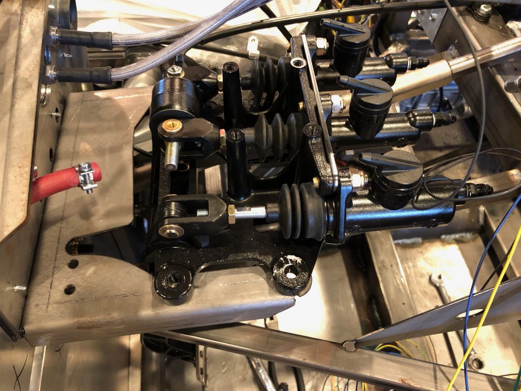
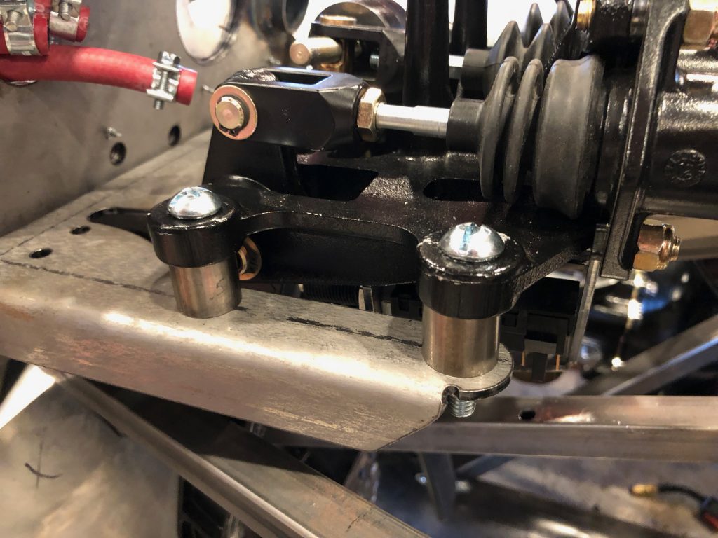
With nothing more that we can do on the engine, I turned back to adjusting the pedal box. The pedal box normally mounts below the support plate, but that puts the pedals very low. I pulled the support plate and reinstalled it below the pedal box. That helped, but I really want to raise them further.

Since I made my own strut mount spacers, I dug through the spacers that came with the kit and found four that were about 5/8″ long. These are perfect; once we have the carpet installed, the brake and clutch pedals will be virtually exactly the same height off the floor as our 911.

Finished Drilling Floor for Seat Tracks, Wheel Spacers and Brake Hoses

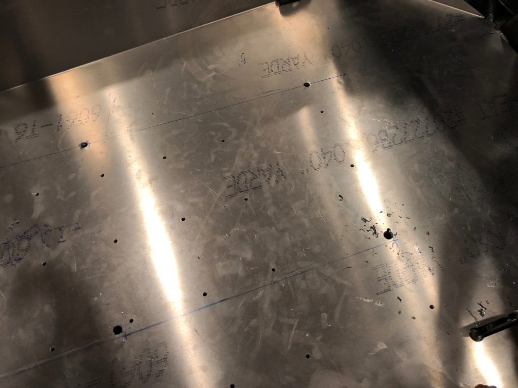
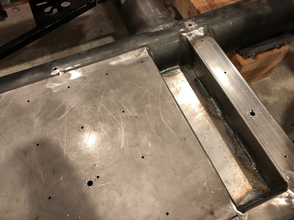
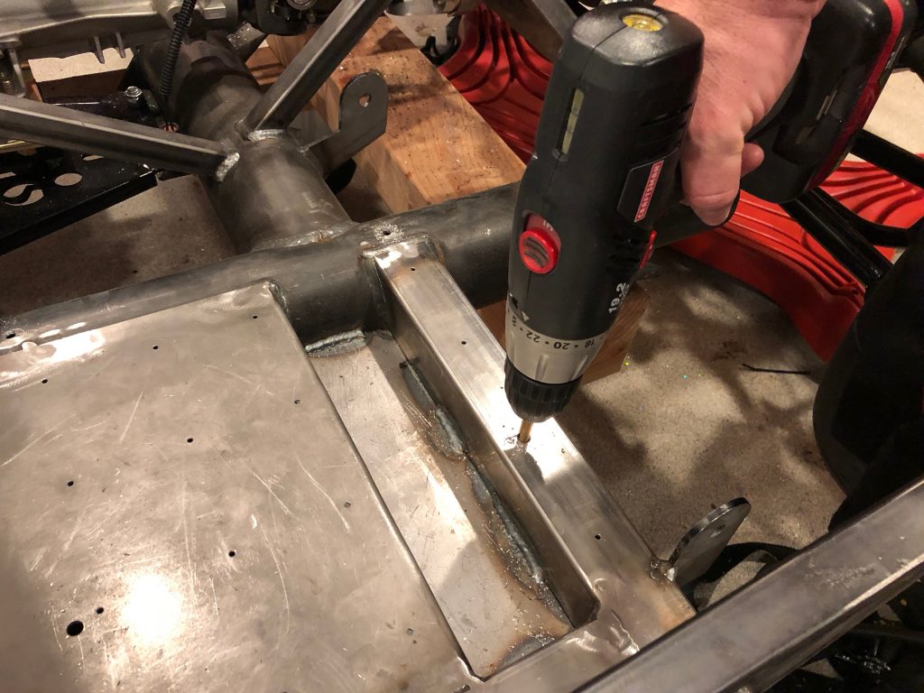
I removed the seat and drilled the final hole through the floor and rear 2″x2″ square tubing.

Afterward, I removed the aluminum floor to get access to the steel floor underneath.

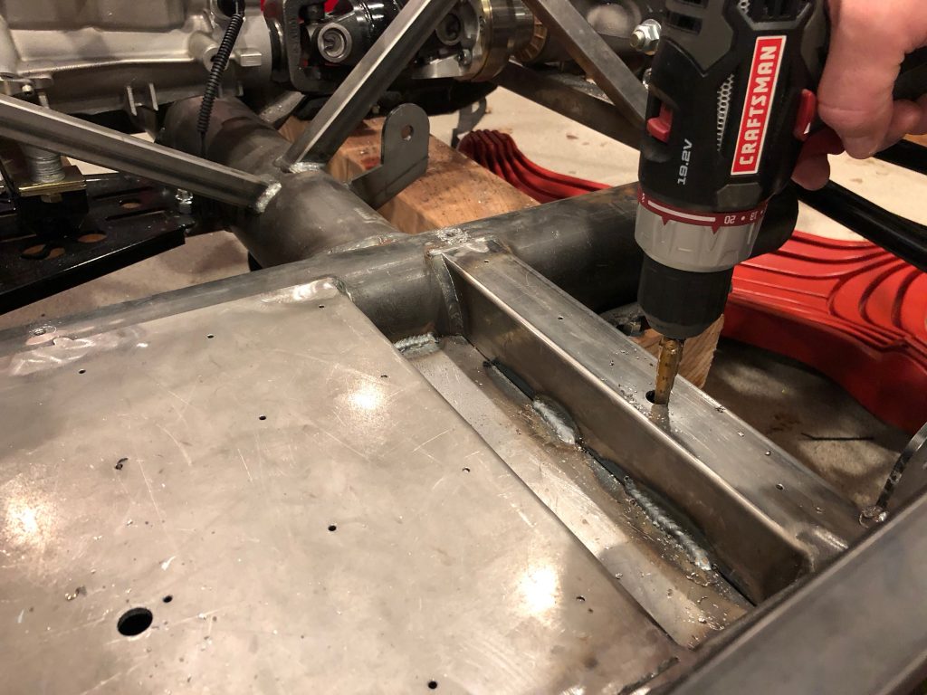
The bolts that attach the outer seat track will go all the way through the lower part of the square tubing. I used the bubble level in the rear of the drill to ensure I was drilling perpendicular to the top surface and then drilled through the bottom surface.

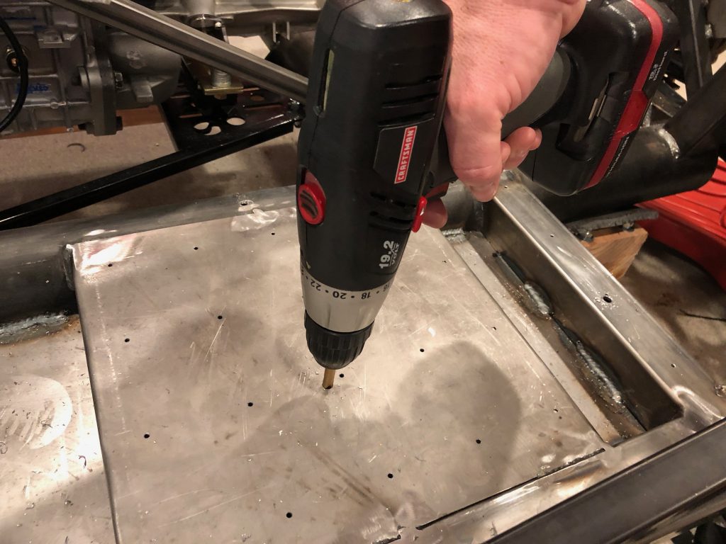
I also drilled through the lower floor the same way.

Afterward, I used the unibit to enlarge these holes to just over 1/2″.

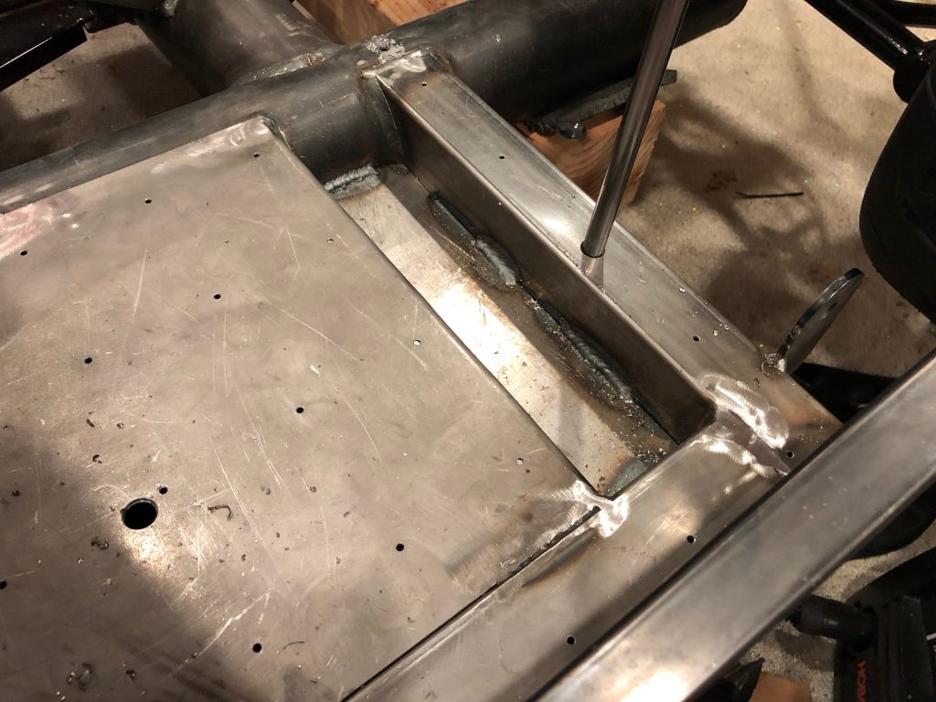
I’m going to be putting pieces of 1/2″ OD steel tubing through these holes and welding them to the upper and lower surfaces before grinding them flat. It’s too late to run the grinder tonight, so I’ll take care of that tomorrow. The spacers will allow me to tighten the bolts properly without deforming the metal. This isn’t much of a concern with the rear 2″x2″ tubing since it has fairly thick walls, but it’s really important with the forward hole through the two thin pieces of sheet steel.

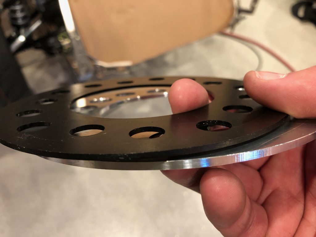
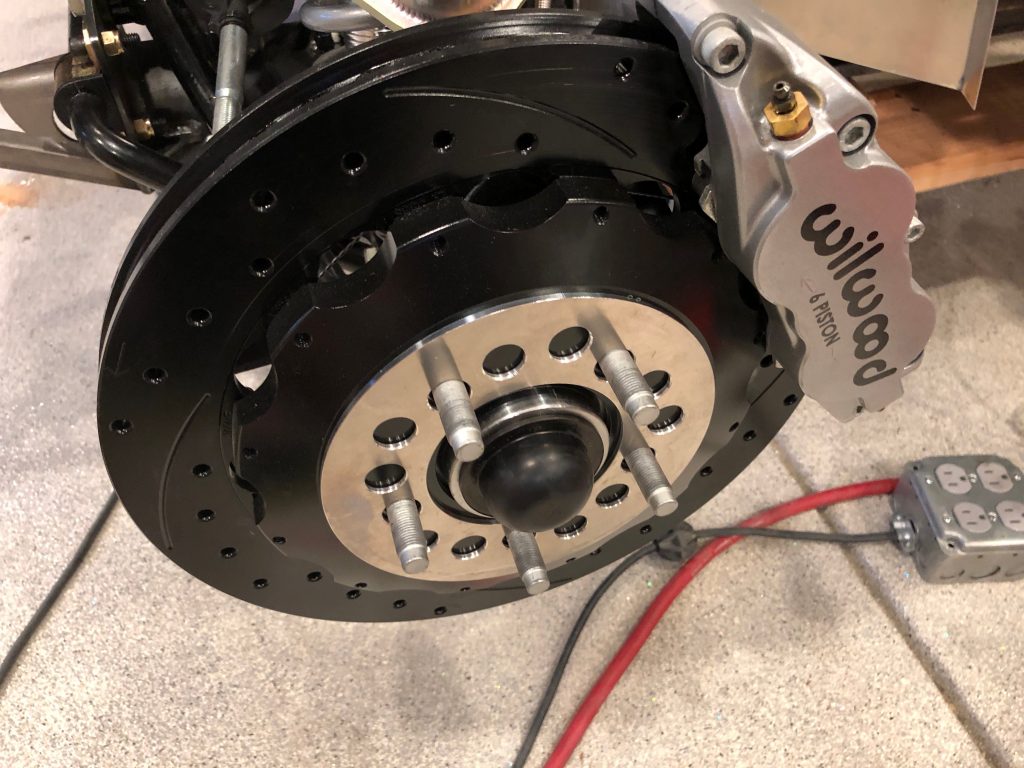
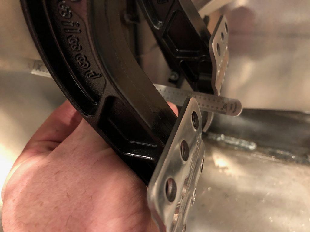
I’ve been concerned with how little space there is between the front brake calipers and the inside of the wheel. If there is even the smallest amount of flex in the wheel, the wheel could hit the caliper. To pick up some extra space, I picked up some new 0.125″  aluminum spacers. These are nearly 0.040″ thicker and quite a bit lighter.

Here is one of them installed. The only disadvantage is that these are made from shiny aluminum and are visible between the spokes of the wheel.

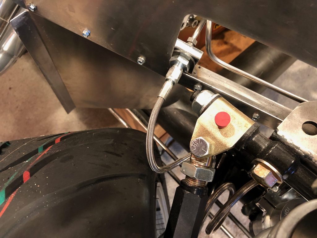
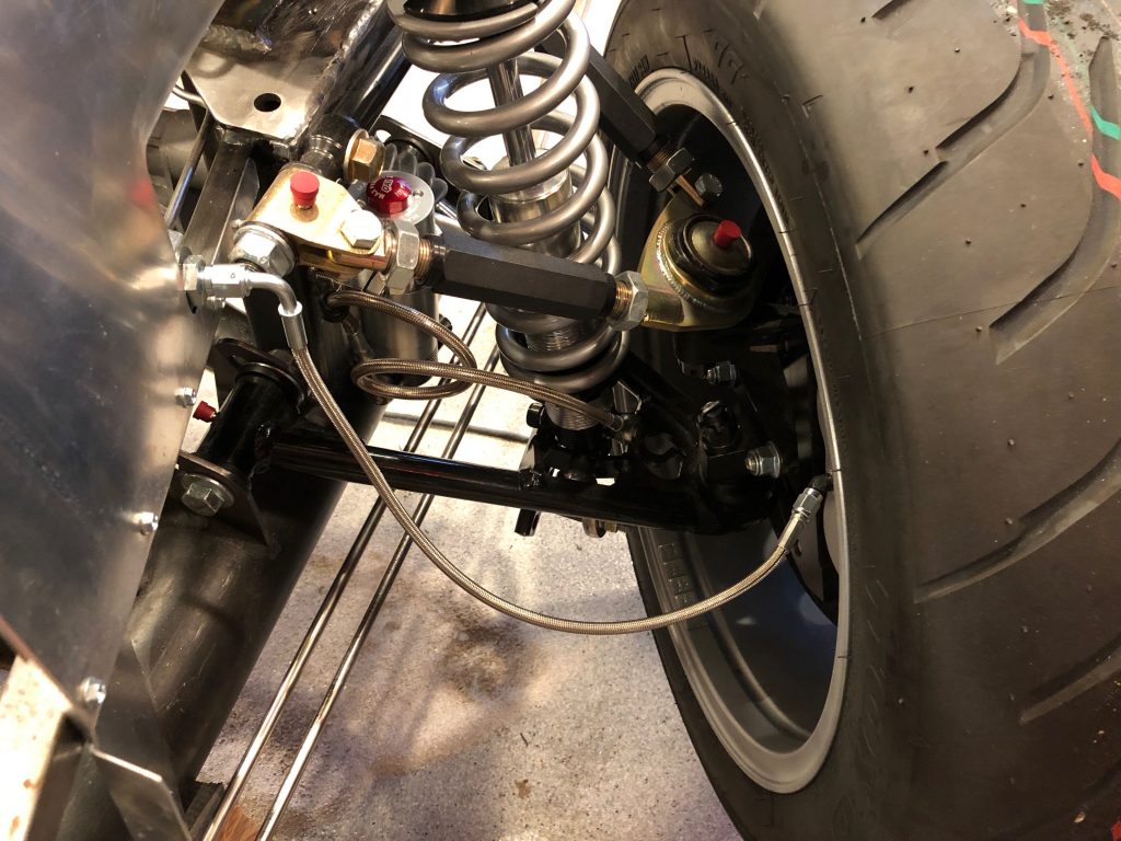
I noticed a while back that my front brake hoses are hitting the tires when turned to the steering stops, so I need to replace these. They’re also 18″ long which is longer than is necessary.

I picked up a couple of 16″ brake hoses with a 90º fitting at one end. Even with the wheel all the way to the stop, there’s plenty of room between the tire and hose.

The hose misses the tire and chassis as they wheel is turned from stop to stop.

When the wheel is at the other stop, there’s plenty of slack in the cable.

Wrapped up Parking Brakes, Reinforced Chassis and Adjusted Brake Pedals

With the final location of the adjustment mechanism determined, I drilled the upper hole and installed a riv-nut. I then taped the ends of the cable and cut off the excess. I’ll replace the tape with a different cable termination during final reassembly.

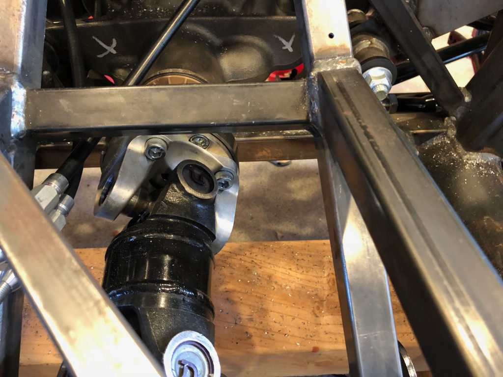
The cables exit the adjuster very close to the driveshaft. I want to add additional support for the cables to ensure they’ll never make contact with the driveshaft.

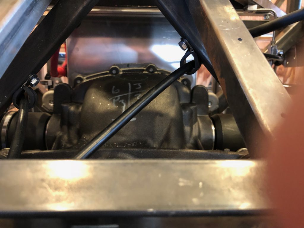
I added a couple of adel clamps above the differential to ensure the cables can’t drop and come in contact with the driveshaft. There’s now no way to even flex the cable enough to contact the driveshaft.

With the shifter and parking brake in place, I trimmed and reinstalled the old cross member in the top of the transmission tunnel.

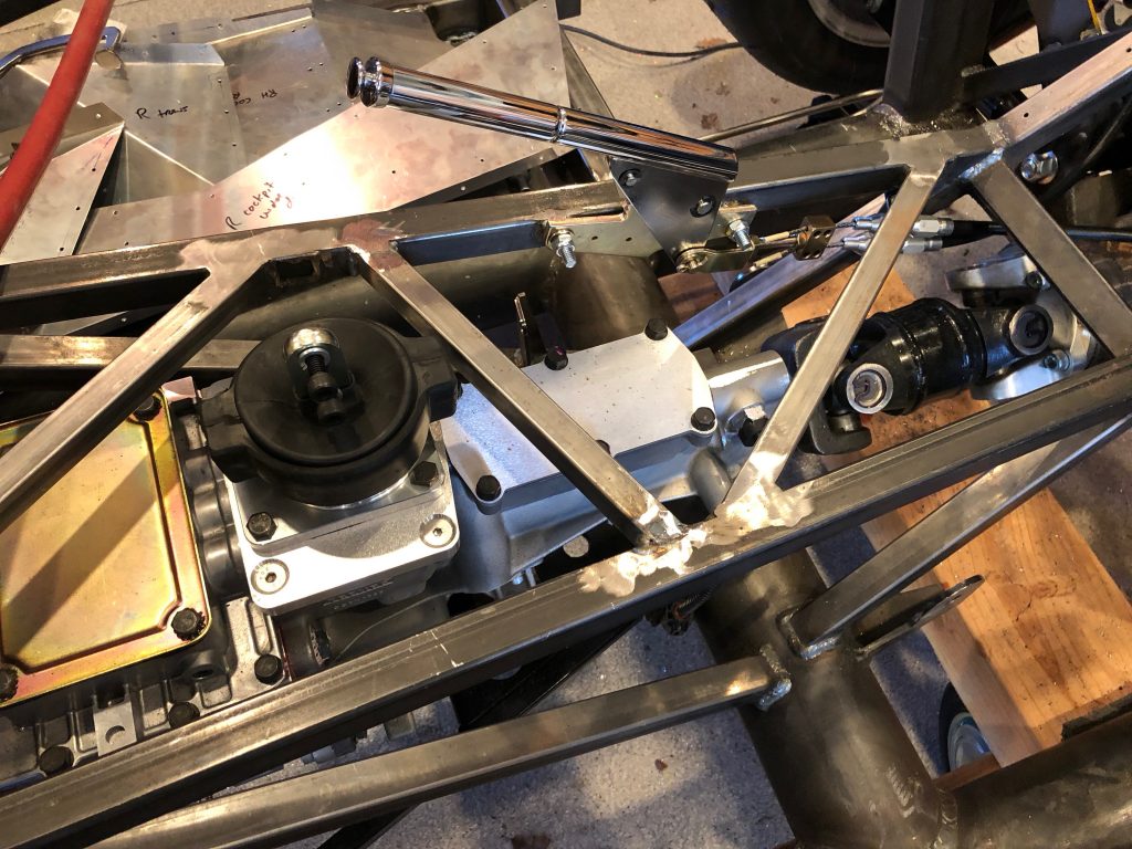
Here’s the finished transmission tunnel. I couldn’t weld the underside, but I’ll take care of that when the chassis is bare again.

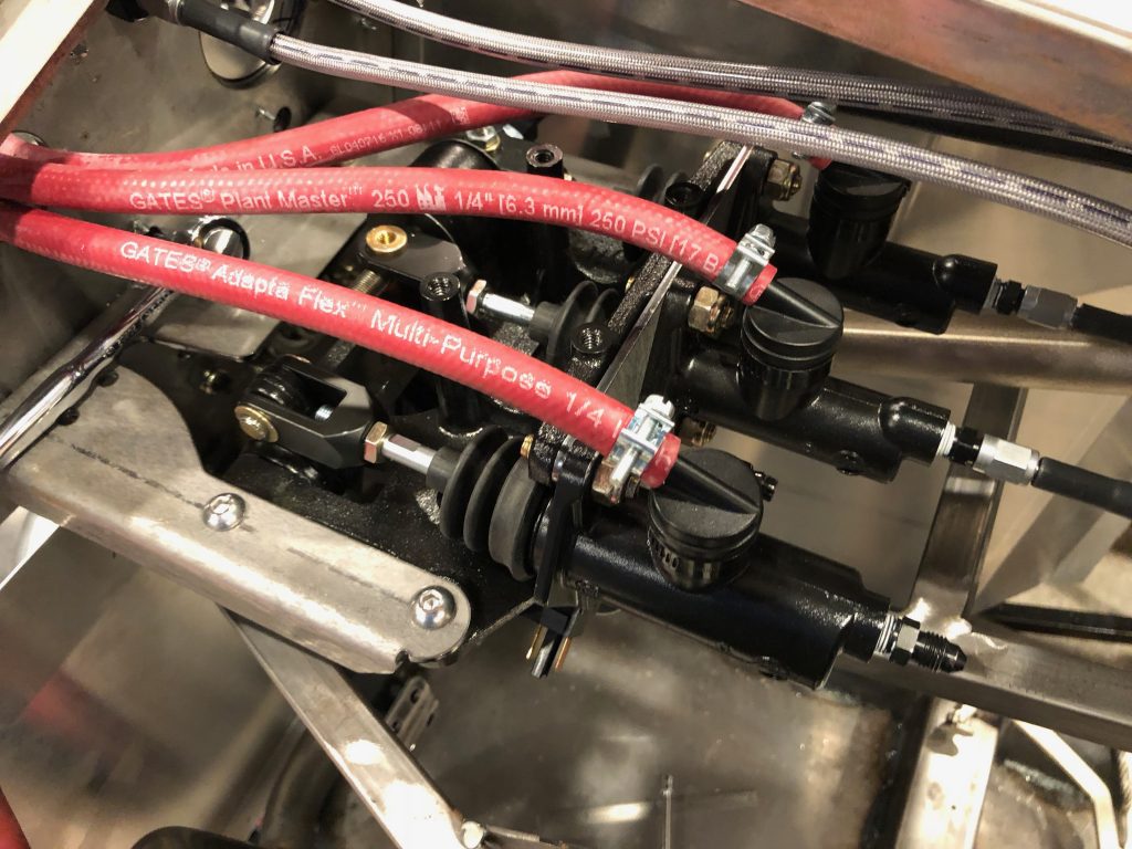
I trimmed 1/2″ from the pushrods of each master cylinder. You can see that the jam nuts are nearly bottomed out on the shafts.

This moves the pedals forward another 2″ or so. They now sit about 5.75″ forward of the firewall. If this isn’t sufficient clearance, there’s plenty of adjustment to move them farther away from the firewall.

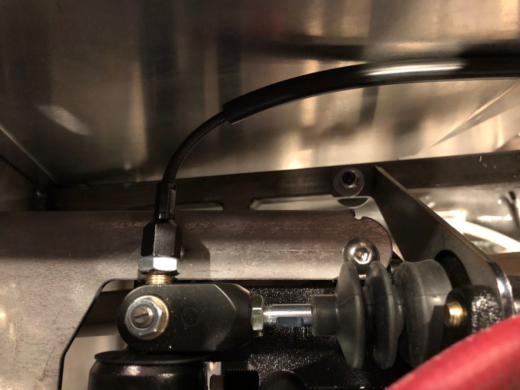
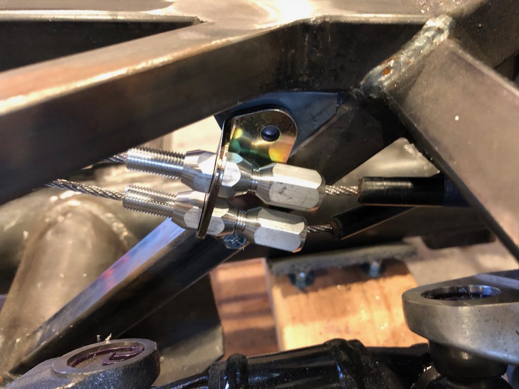
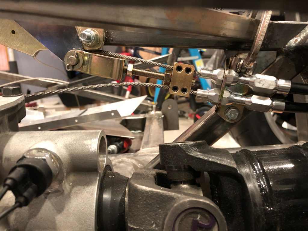
I then installed the adjustment cable. I left a section without the housing to allow a tighter bend radius. I was worried that this was going to be too tight of a bend and that I was going to have to go through the sidewall of the footbox and into the engine compartment, but this works very well.

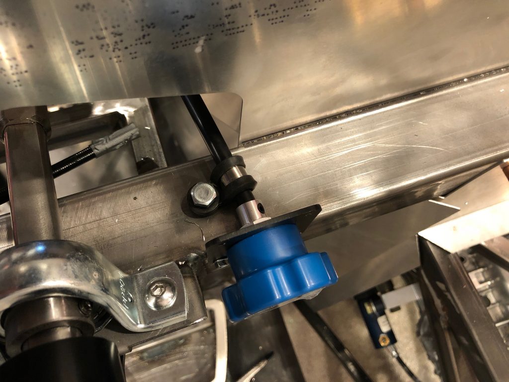
I installed the other end just to the right of the steering shaft. I could only drill through the lower two holes, so I added an adel clamp to further secure the assembly. It’s plenty rigid, especially for the infrequent use this will see.

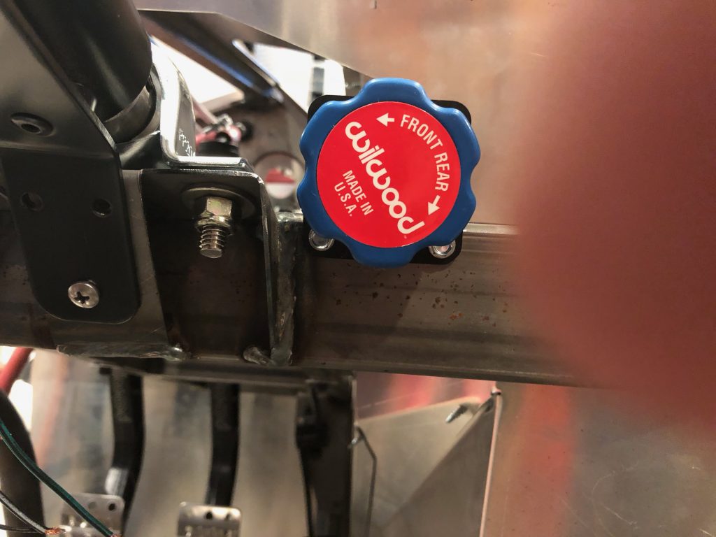
Finally, I installed the appropriate label to mark the direction of rotation necessary to achieve the desired biasing. I won’t be able to see the label from the seat, but it’s pretty easy to remember that right is rear.

Installed Parking Brake

I’ve been holding off on installing the parking brake until the gear shift was relocated. With the gear shift in its final location, I can now determine the final location of the parking brake lever. I picked up a Lokar hand brake from Summit Racing to replace the unit from Factory Five. It came preinstalled with a simple bracket, but the Wilwood universal parking brake cable kit came with the adjustable bracket shown at the bottom left. It was a simple matter to swap this bracket out.
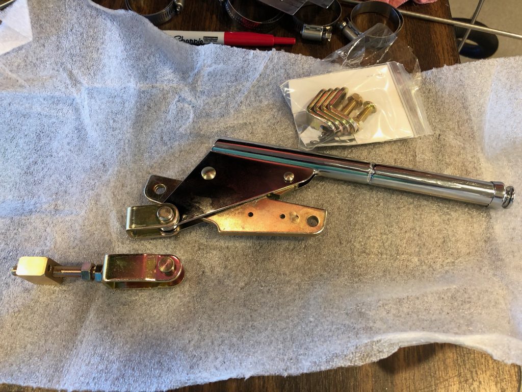
I temporarily positioned the parking brake handle and the adjustment mechanism that secures the end of the cable sheath.
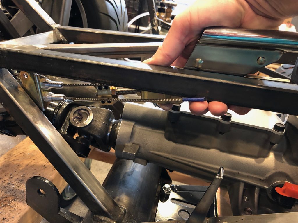
The adjustment mechanism will be bolted to the side of the tubing at the aft end of the transmission tunnel. Because of the angle of the tubing, only one of the two bolts will land on a piece of tubing, so I welded in a piece of thin plate steel.
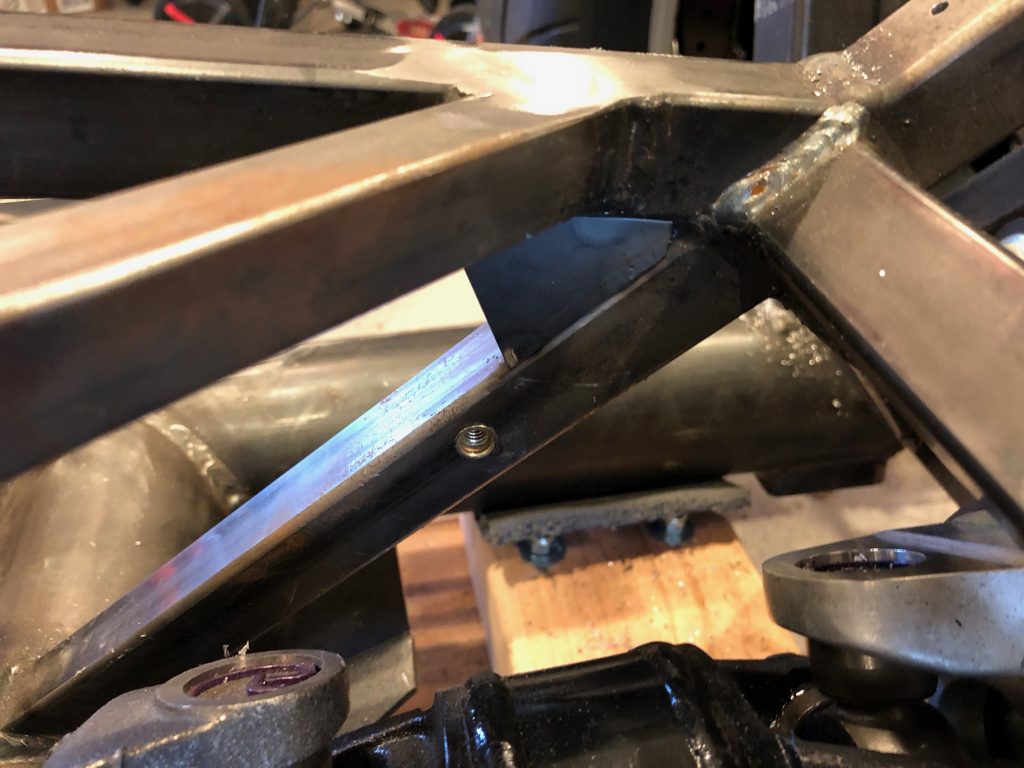
This is approximately the angle that the adjustment mechanism will sit at. I’ll drill and install a rivnut for the upper bolt once I determine the final angle of the adjustment mechanism.
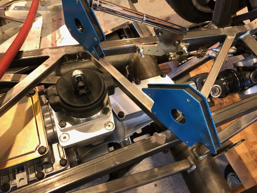
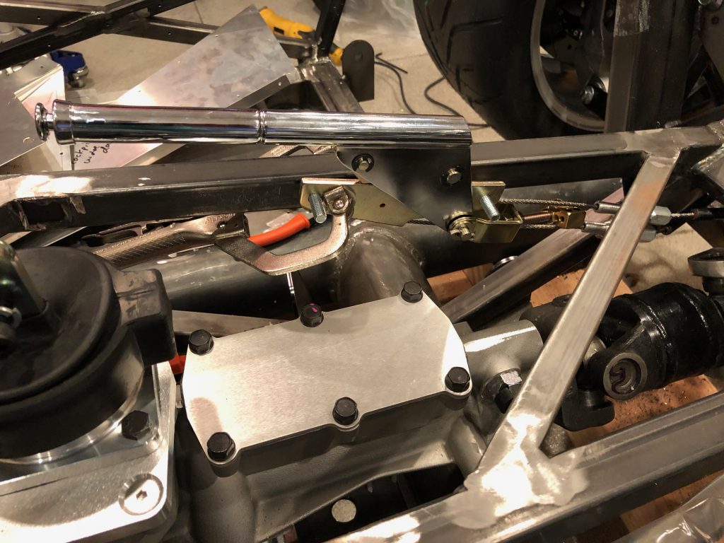
I temporarily clamped the parking brake in to see what kind of clearance I’d end up with between the gear shift and parking brake handle. This looks like it is going to work out well. The final check is to see how comfortable this is to pull when sitting in the car.
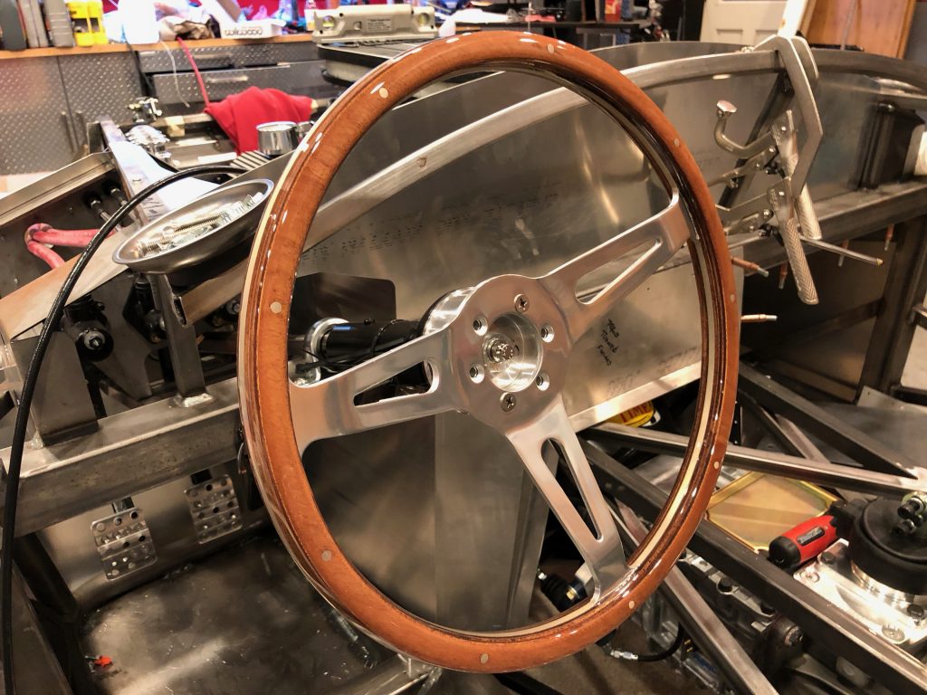
I temporarily installed the steering wheel while I was at it so that we could determine a comfortable seating position.
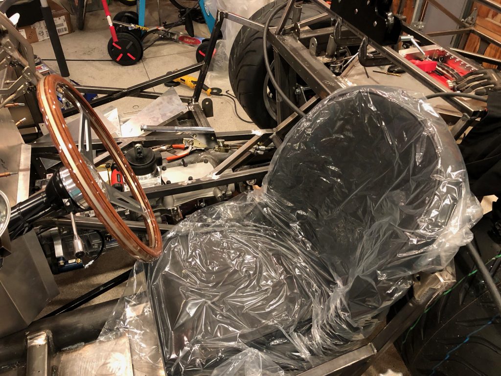
I sat one of the seats in the driver’s side of the cockpit and Jenn and I both got in to evaluate the position of the parking brake, gear shift lever, steering wheel and pedals. It looks like the parking brake location is going to work out great. Even with the mid-shift, we also determined that we want a gear shift lever that tilts forward slightly to put the shifter in a more natural position.One unfortunate discovery is that our plan for a dash that curves down to intersect the transmission tunnel won’t work because it will push my knee into the side of the steering wheel. It looks like we’re going to go back to the stock dash panel (though we’ll order a blank so that we can lay out the gauges where we want them.

One unfortunate discovery is that our plan for a dash that curves down to intersect the transmission tunnel won’t work because it will push my knee into the side of the steering wheel. It looks like we’re going to go back to the stock dash panel (though we’ll order a blank so that we can lay out the gauges where we want them.

Finally, we determined that the pedals need to move forward a bit. This is a fairly common tall-guy mod, so it shouldn’t introduce any problems.
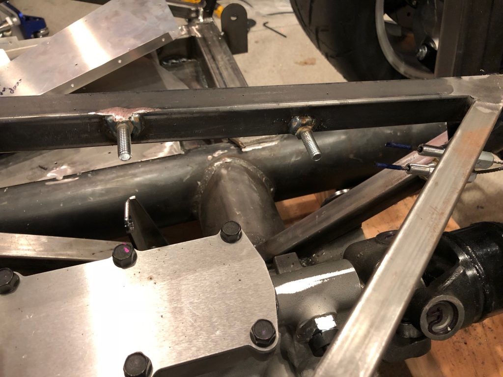
With the final location of the parking brake determined, I welded on the forward bolt.
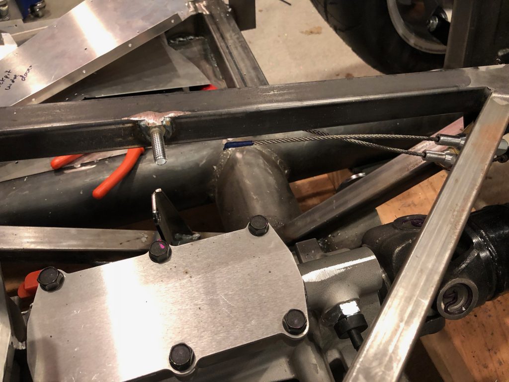
I then installed the parking brake and clamped the rear bolt in position before welding it as well.
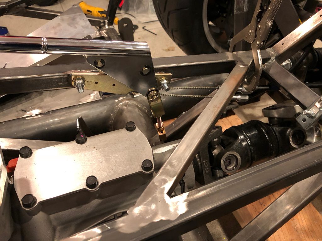
I then bolted the parking brake in place so that I could make the final determination of how long to cut the parking brake cables and the angle of the adjustment bracket.
I re-routed the parking brake cable from the caliper.
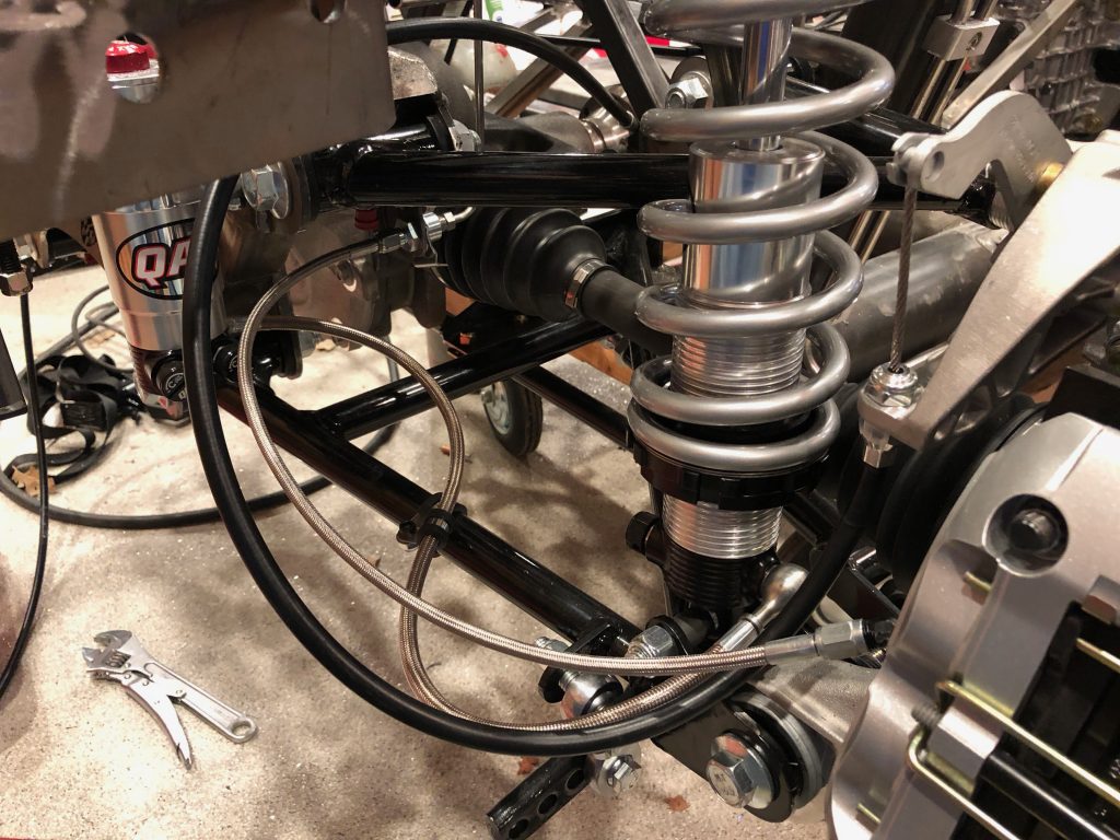
It now routes under the aft diagonal chassis member where I installed a 1/4-20 rivnut and an adel clamp.

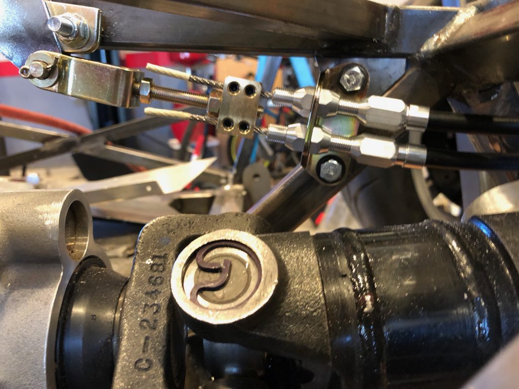
After trimming the cable sheaths to length, I ran the cables through the block and tightened down the set screws. I test the parking brake and it locks the wheel securly at about the halfway point in the pull. I have plenty of adjustment if the cable stretches over time.
Rear Brake Line

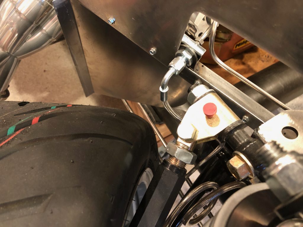
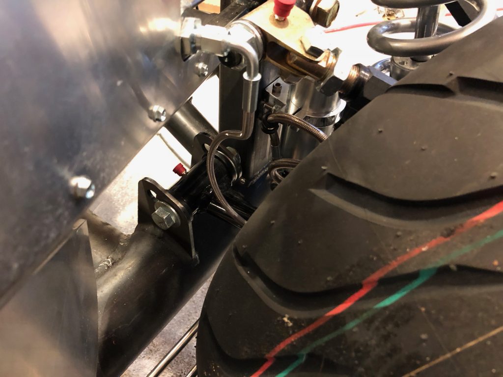
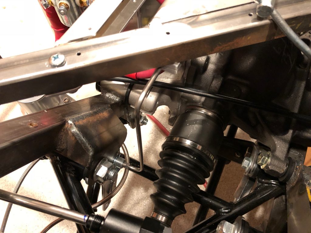
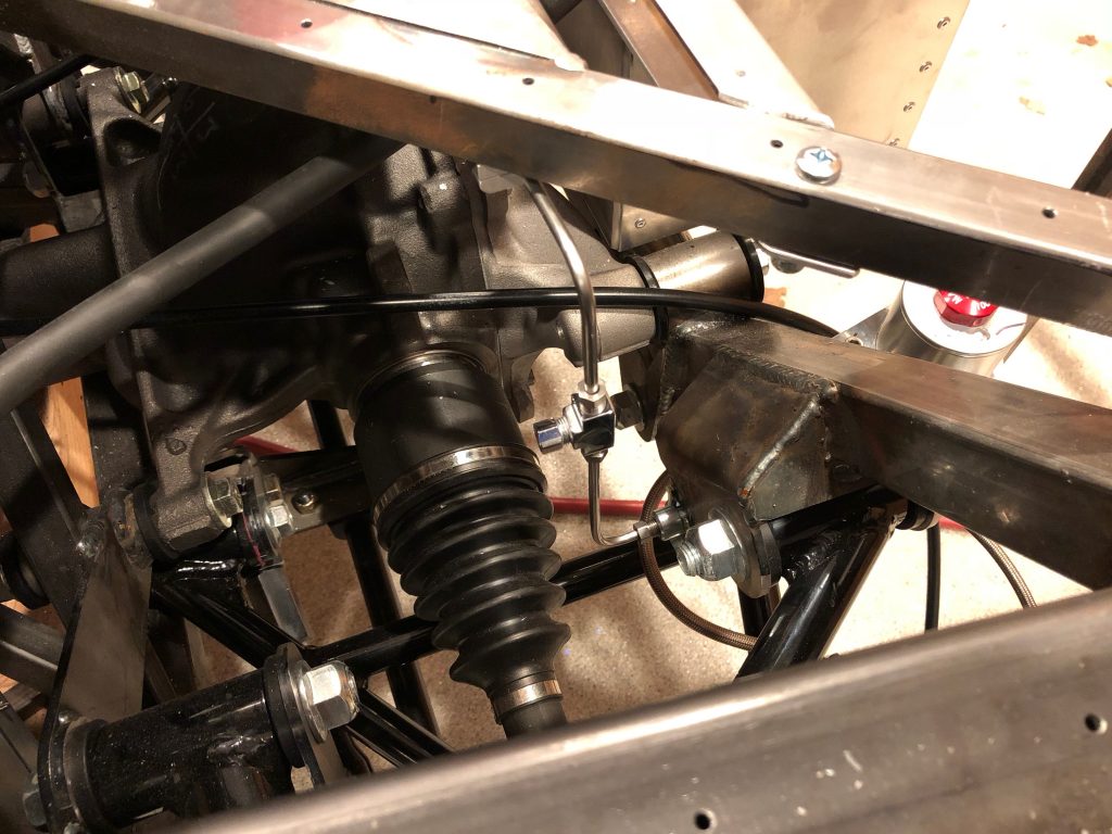
After I boogered up the rear brake line last night, I decided to reroute it to simplify the necessary bends. When I first fabricated the rear brake line, I hadn’t installed the battery box, so I wanted to keep it tight to the other tubing. Now that I know where everything sits, I realized that it wasn’t necessary to have such a complex routing. The new routing has the brake line turn straight up from the fitting on the right side. It’s hard to tell from this picture, but the line is completely behind the inner CV boot. Even at full compression travel, I don’t think the inner CV boot could ever flex as high as the brake line, but I wanted some lateral clearance as well.

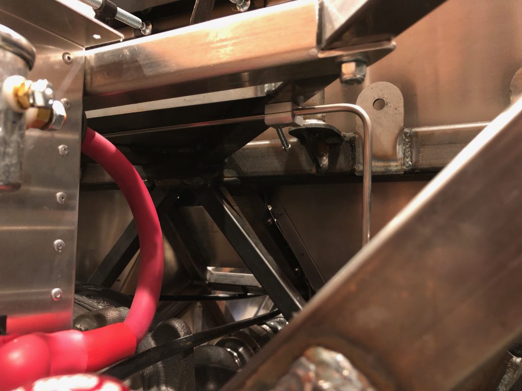
I installed a couple of rivnuts on the angled square tubing to secure the brake tubing where it crosses the chassis.

The second brake line clamp is on the left diagonal square tubing.

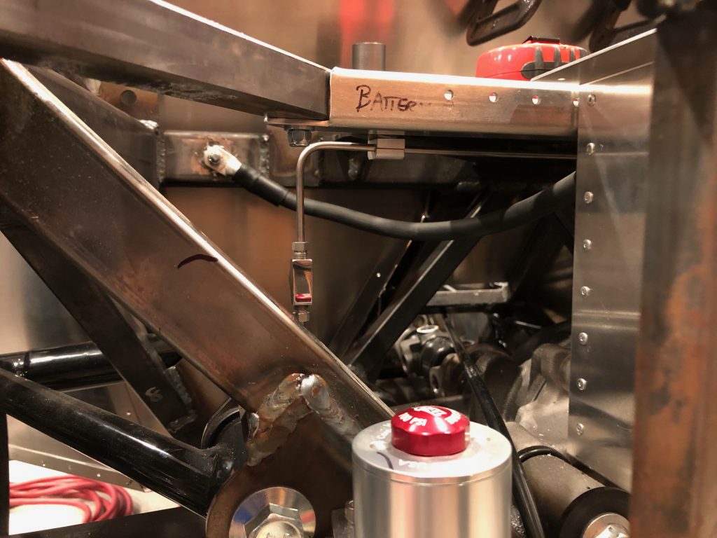
I put the tee in the vertical leg on the left side. I haven’t figured out which direction I’m going to have the third leg go from here, but it won’t interfere with any part of the suspension or drivetrain regardless of the direction.

Trunk Aluminum, Fuel Tank Stabilizers and Rear Brakes

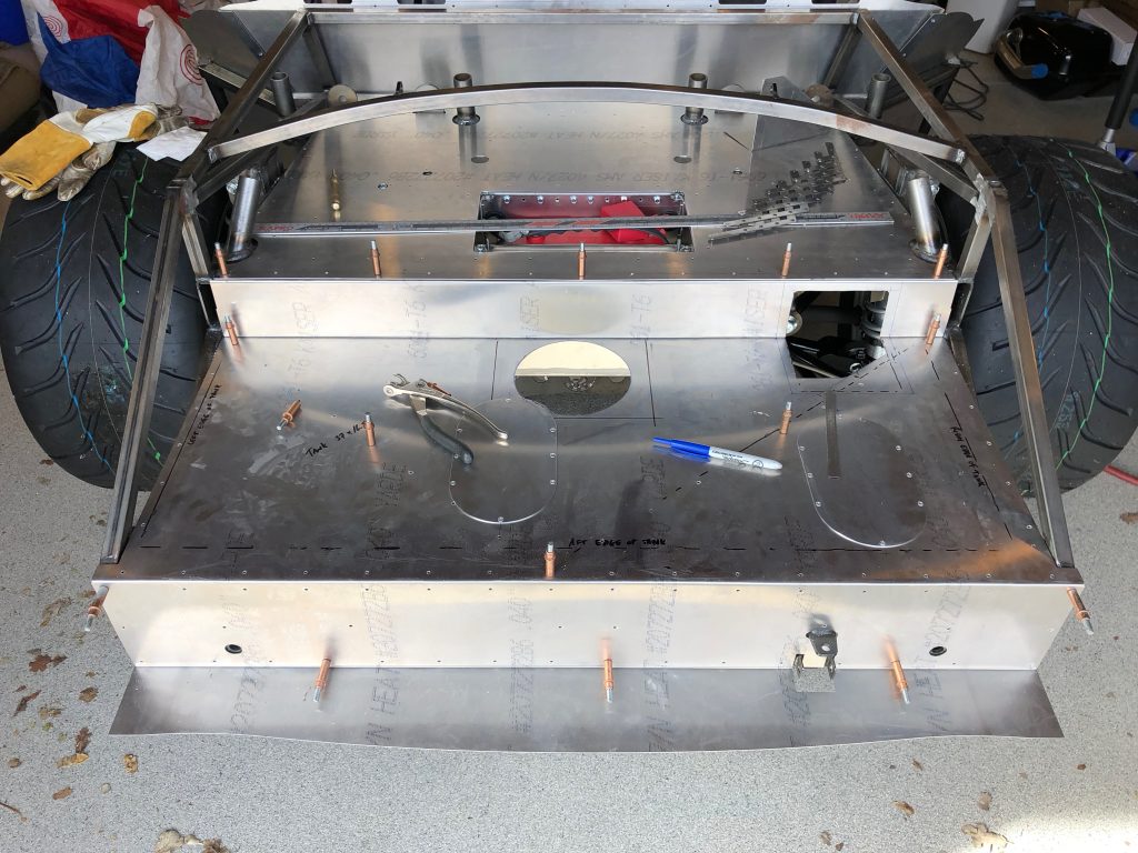
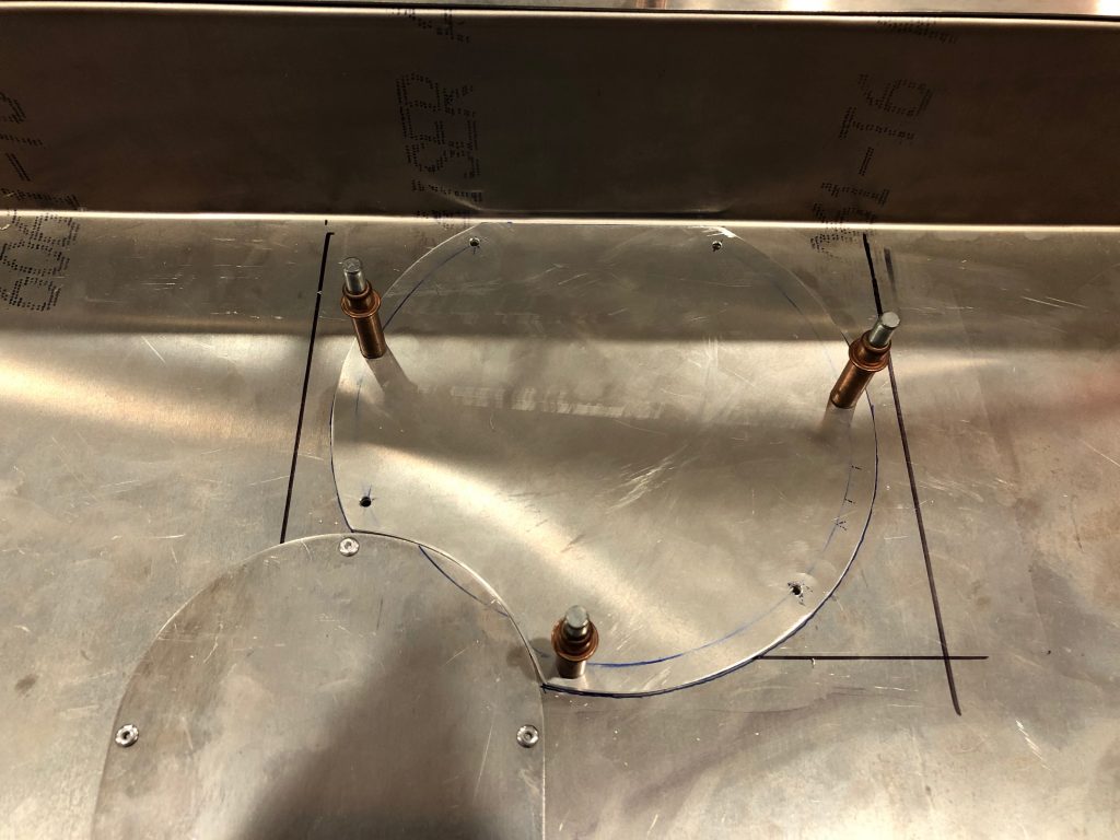
Before I can install the fuel tank for good, I also needed to wrap up the trunk aluminum. I had previously drilled the upper trunk floor, but I never did the same for the lower trunk floor. I started by removing the tank (hopefully for the last time before the final reassembly). I needed to do this so that I could mark the chassis tubes on the underside of this sheet. After laying out all of the holes, I drilled the sheet to the chassis tubes. You can also see that there is a row of rivet holes tying the upper trunk floor to the lower trunk floor.

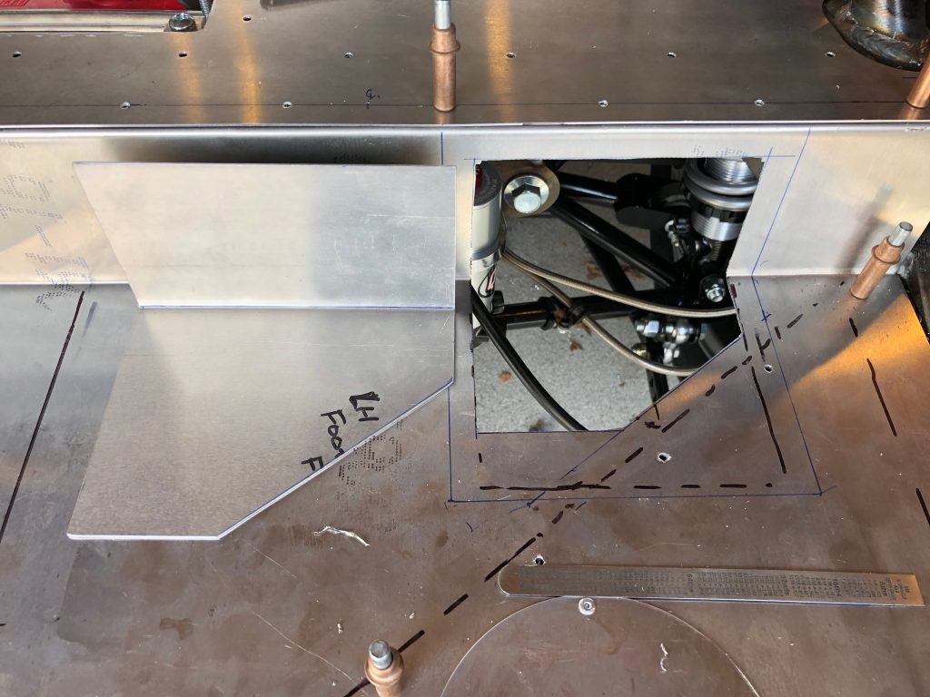
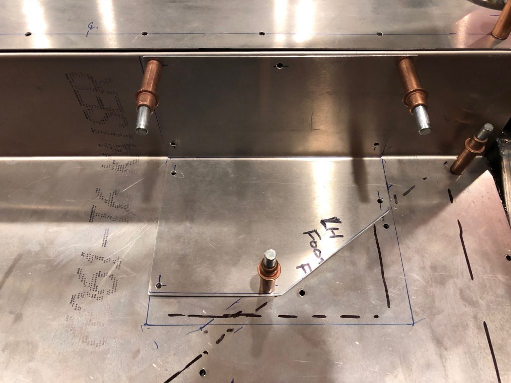
With the lower trunk floor in place, I cut and bent a piece of scrap aluminum to make the access panel cover for the fuel sender and fuel return and vent fittings.

I drilled this to the floor with a #30 bit for now. I’ll open these up for the right size screw before installing nutplates.

I also cut out and drilled an access panel cover for the fuel pump and supply fittings.

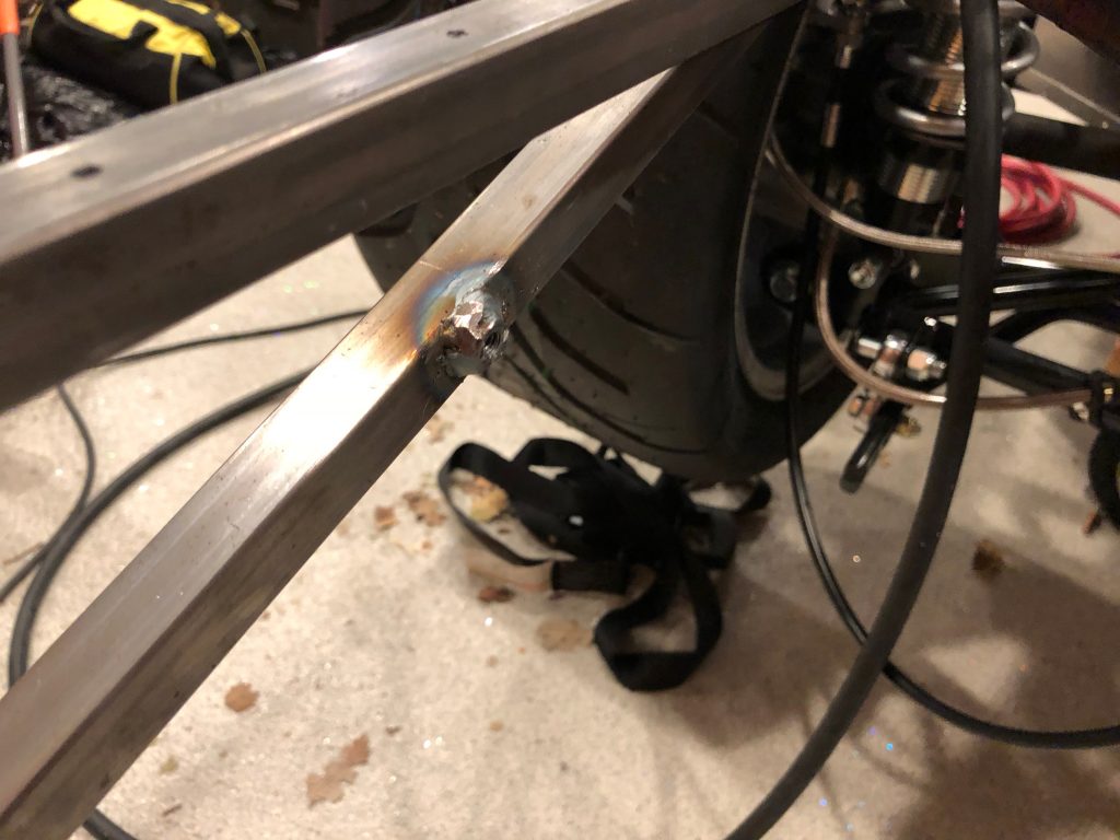
The fuel tank is narrower than the cavity in the chassis that it fits within, but I don’t want the fuel tank to be able to slide from side to side. To prevent this, I drilled a 1/4″ hole in the lower diagonal tube on the inside face and welded on a 1/4-20 nut.

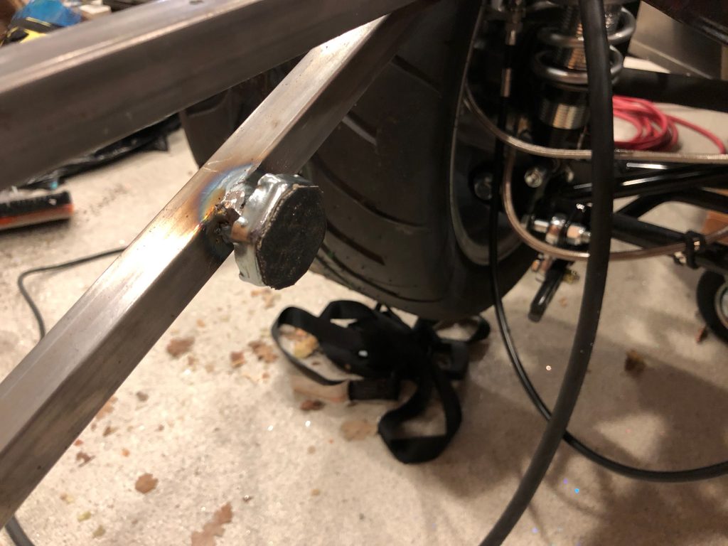
I threaded a leveling foot with threaded stud into the nut. I had previously bonded a piece of the same reinforced rubber sheeting onto the foot where it will contact the tank.

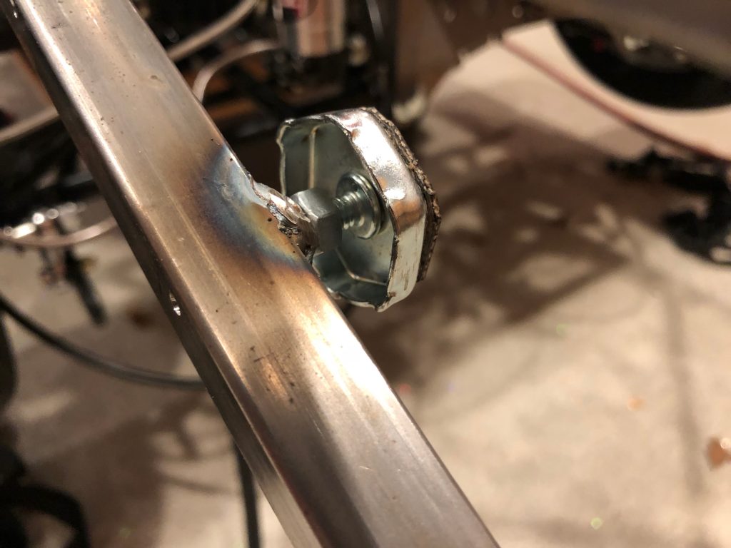
You can see on the other side that there is a run nut threaded onto the shaft as well. Once the tank is installed, I can tighten the foot against the tank and lock it into position with the jam nut.

Before reinstalling the tank, I wanted to wrap up the rear brakes. I started by adding a brake line clamp on the right diagonal tubing. Unfortunately, when I was trying to wrap up the other end of this piece of tubing, I botched the flare. I don’t think the tubing is salvageable, so I’ll probably have to fabricate a new piece.