Ordered InfinityBox

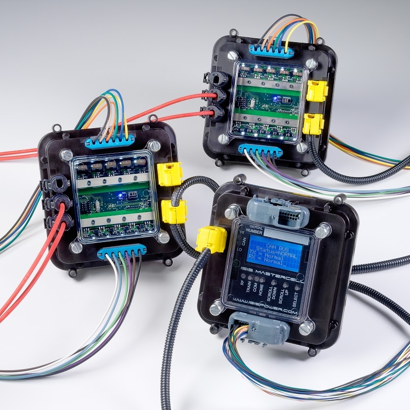
I’ve been working on our electrical system configuration for weeks now and we’re finally happy with the plan. We’re installing the following items from InfinityBox:

  • InfinityWire 20-circuit Wiring Harness

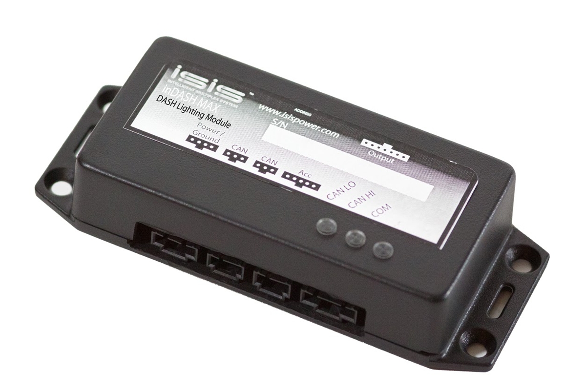
  • inDASH MAX Dash Lighting Module

  • inLINK RF Control Module

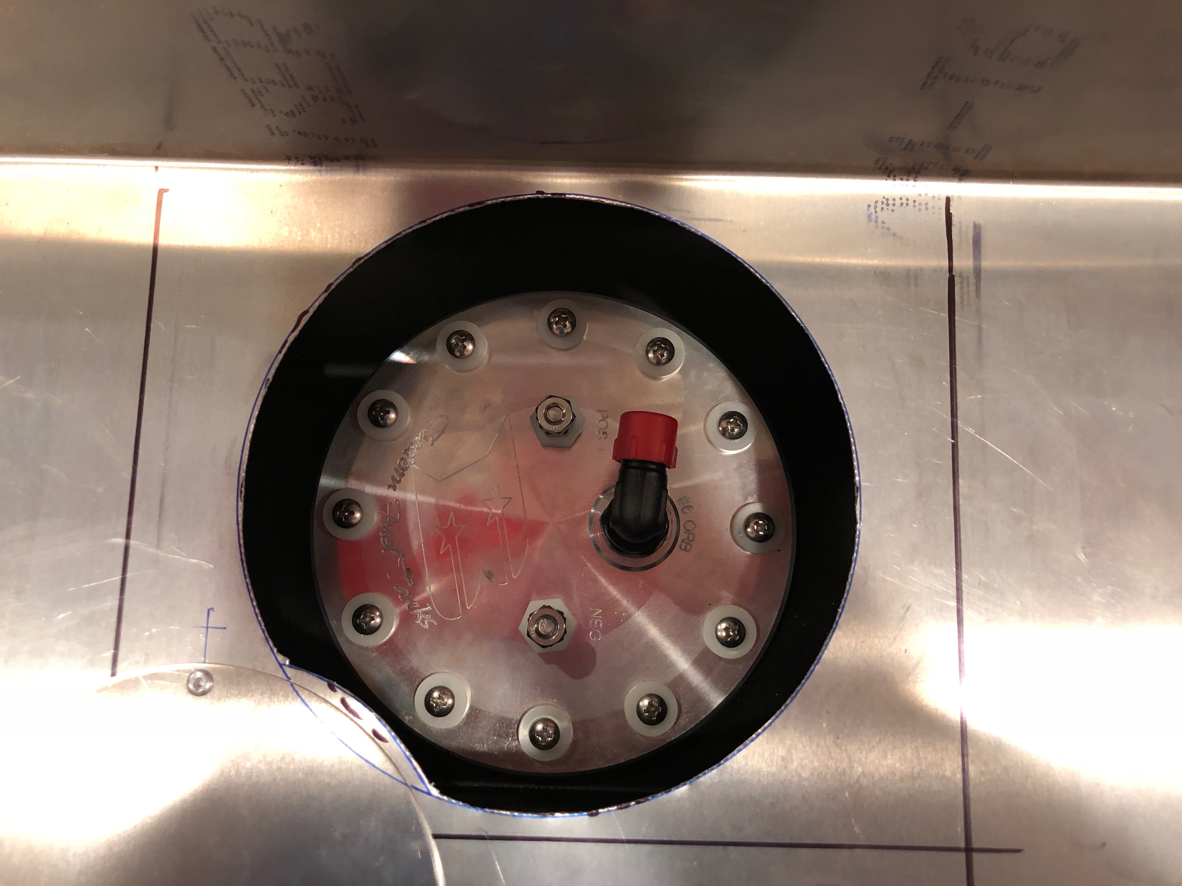
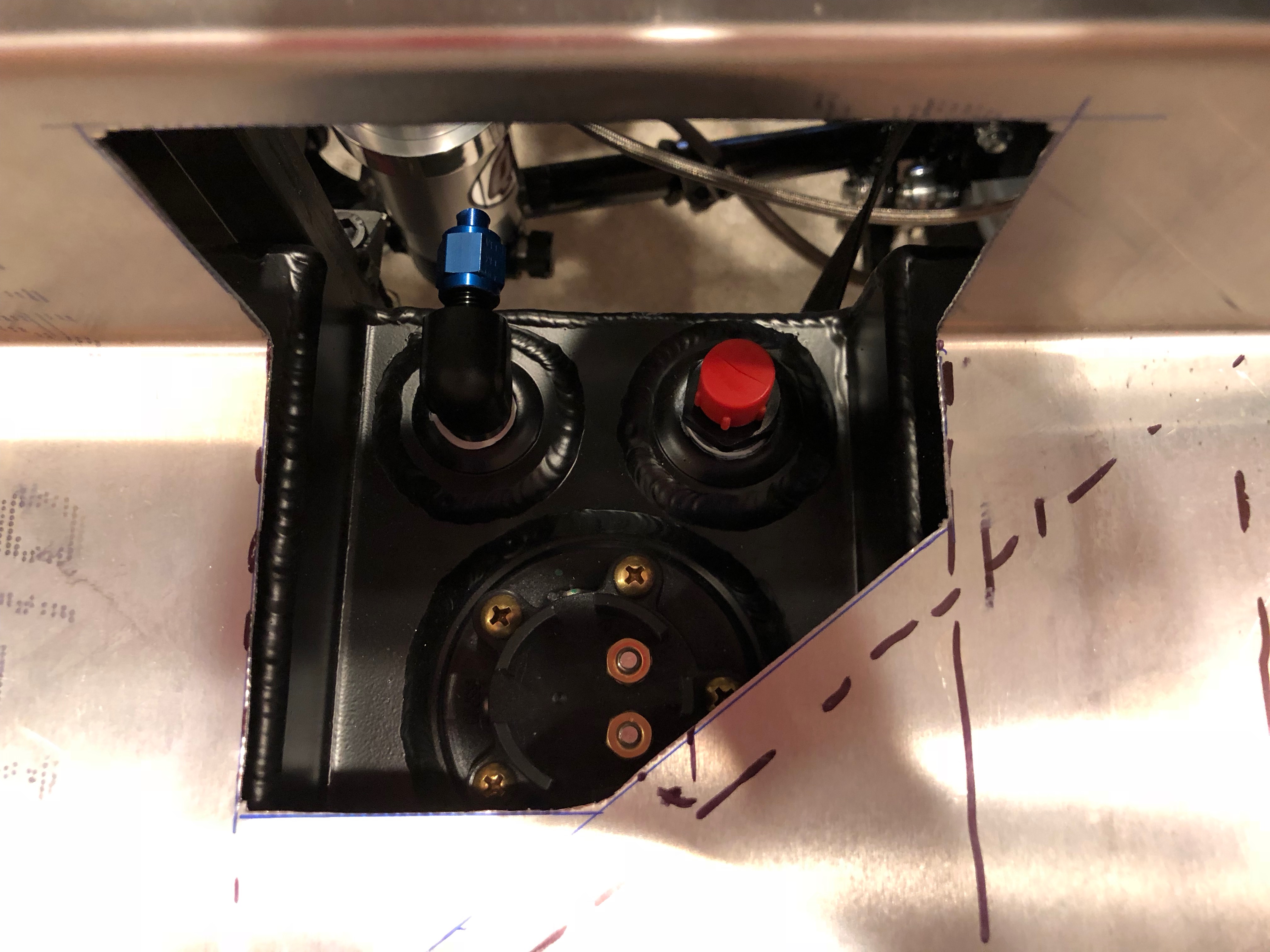
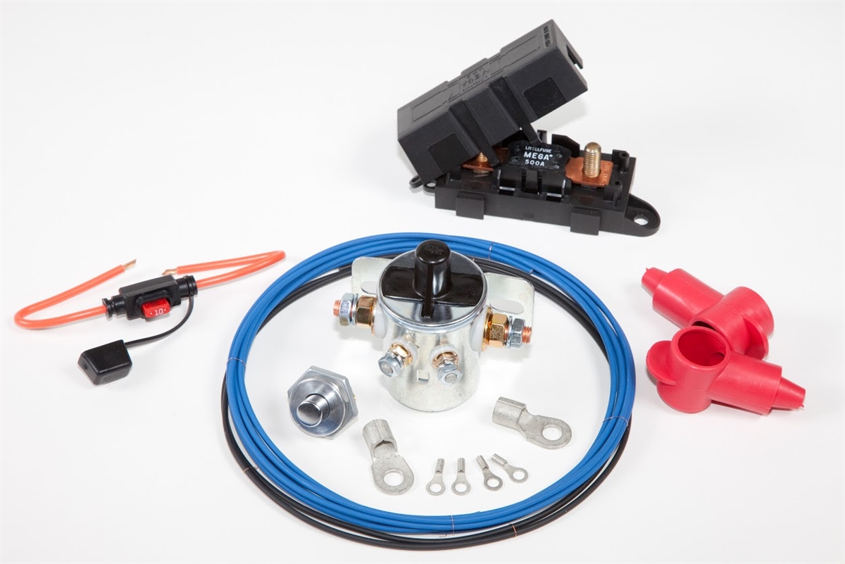
  • inRESERVE Active Battery Monitoring

This will let us control the following electrical circuits in the car:

Front

  • High-beam headlights
  • Low-beam headlights
  • Parking lights
  • Turn signals
  • Hazard lights
  • Ignition
  • Starter
  • Heater
  • Horn
  • Radiator fan
  • Electric Power Steering

Back

  • Brake lights
  • Parking lights
  • Turn signals
  • Hazard lights
  • Seat heaters
  • Stereo
  • Interior lights
  • Trunk light
  • inRESERVE solenoid

Positive Cable Termination

I purchased some 1.1″ heavy-duty heat-shrink with adhesive for the battery cable connections. After shrinking, this stuff is pretty thick and very tough. Most heat-shrink tubing is more like a rubber sleeve, but this is closer to rigid plastic, so it should provide outstanding strain relief for these terminals.

I then slipped a rubber boot over the end. All power leads will have boots for protection.

This was a pain in the ass to slip over the super-thick heat shrink tubing, but it should work fine.

Ordered Switches

We ordered our switches tonight from Billet Automotive Buttons in Australia. Samples are shown below. They have four sizes of buttons (16mm, 19mm, 22mm, and 28mm) in both black and stainless and can be custom laser etched with any text or graphics you want. All of our switches will be 22mm, momentary stainless with logos on the button and no text around the edge. We ordered switches with the following logos:

  • Low-beam headlight with blue ring
  • High-beam headlight with blue ring
  • Parking lights with orange ring
  • Hazard lights with red ring
  • Fan with green ring
  • Interior lights with white ring
  • Stereo with green ring
  • One surprise button we’ll reveal later 🙂

We also ordered the following 14mm indicators:

  • High-beam indicator with blue light
  • Left and right turn signal arrows with green lights

I also ordered a single 16mm red light with the word “ALARM” laser etched around the edge.

Passenger Foot Box Side Protection

I took some careful measurements to ensure the side protection tubing would fit inside the passenger foot box and then trimmed it to fit tight against the square and round tubing. This is a duplicate of the tubing on the driver’s side, but I needed to make it a mirror image of the other side in order to fit.

After tacking it in place, I removed all of the sheet metal for the passenger foot box and welded it in place.

Here’s the upper weld. Not the prettiest, but good penetration on both sides. I had to keep repositioning the gun to get a decent angle on the weld which made it hard to keep any consistency around the perimeter.

I had a little better access at the other end, so I was able to make a somewhat more attractive weld. This should provide substantially more side impact protection.

Parking Brake Cable Routing

I fit the end of the parking brake cables into the caliper. This is the right side, looking forward.

I looped it back up near the upper trunk floor where it’s basically a straight shot to the top of the transmission tunnel.

I routed the other cable the same way and then routed them over the pumpkin to the top right side of the tunnel. I still need to figure out where the bracket and parking brake handle will mount.

Primary Power Wires

I cleaned off a section of the chassis and ground off the plating from a 5/16″ bolt and clamped it in place.

I welded around the bolt head to create a grounding stud for the battery.

I’m using 2/0 welding cable for the starter and ground cables. I crimped a connector on the end and temporarily routed it to make sure it won’t hit anything. I’ll add some heavy duty heat-shrink tubing over the joint when it arrives.

I temporarily routed the battery positive cable from the right side of the battery box down to the lower right side of the tunnel.

It snakes over the 4″ round cross tube…

…and up the diagonal on the right side of the transmission.

It then drops down the diagonal to the right of the bellhousing and will loop back to the starter. I’m not 100% sure I like this routing. The other option is near the top of the transmission tunnel, but I want to stay away from the parking brake cables and I’d like to keep it separate from the other electrical wires.

Fuel Hardlines

I straightened a 20′ roll of 3/8″ stainless tubing and then cut it in half. I made a few bends to allow it to run under the passenger seat just outside of the 3″ round tubing.

I flared the end and added a flare nut and sleeve. The fuel filter will mount here and be supported by a large adel clamp.

I fabricated a fuel line with a -6 ORB 90º connector on one end that hooks to the fuel pump.

It snakes forward and connects to the fuel filter.

I then fabricated the return line so that it parallels the supply line under the seat and up the diagonal support.

It will run just under the fuel filter and will have a fitting where I’ve made the mark. A flex line will connect it to the return fitting on the tank.

Cockpit Floors and Transmission Tunnel Mod

I laid out the holes and drilled the cockpit floors and outer panels below the doors.

The holes follow the perimeter 2″x2″ square tubing and uniformly cover the steel panel that supports the seat. Some of these may not get used depending on where the seat tracks bolt.

We’re moving the shifter to the middle location on the transmission, so I cut out the diagonal support that would interfere. I may weld this in farther aft once I have the new shifter and parking brake installed.

There is now plenty of room for the new shifter.

Passenger Foot Box and Forward Tunnel Cover

Before I can determine the routing location for the wiring and tubing from the front to the back, I wanted to get most of the aluminum chassis panels in place. I started by clecoing the passenger foot box in place. There is substantially more space between the headers and the foot box on this side. I’m considering expanding this foot box, but I want to get the seats in and see if it is necessary before doing so.

I also installed and drilled the forward tunnel cover. I need to trim the inboard foot box panels to align with the edges of this panel before drilling them together.

Cut Access Holes in Lower Trunk Floor

I cutout the holes in the lower trunk floor for accessing the fuel pump, fuel level sender, and fittings and then tested the fit to see if the holes need to be adjusted.

The hole for the fuel pump should work just fine. I think it will slip around the little bump out on the lower left if I ever need to remove it.

The hole for the fuel level sender will probably need to be enlarged slightly to allow the sender to be removed. I’ll mark and trim that before cleaning up the holes and fabricating cover plates.