Strut Hoses and Trunk Aluminum

The parking brake cable rubbed against the strut reservoir hose, so I used a zip-tie and a short piece of plastic hose (extra from the brake bias adjustment cable housing) to tie them together while keeping them separated.

The hoses connecting the front struts to the reservoirs have a hose that is too long for our application. I had the hoses just making a gentle bend between the two and it went so high that it interfered with the upper control arm. I removed both reservoirs and put an extra bend in the hose. This places the hose completely clear of both the upper and lower control arms and should easily handle the flexing during suspension travel.

I realized that there were a couple of extra pieces of trunk aluminum that I never drilled to the chassis, so I took care of that before heading to bed.

Finished Steering Linkage

I cut the tie rods so that I could thread on the bump-steer linkage. Despite the steering rack being centered, I needed to cut off 1/2″ on the right and about 1 1/4″ on the left. This lets me thread the bump-steer linkage on fully and have a bit more toe-in than you’d ever want.

The bump steer kit from Fortes Parts has a tapered shim that fits around the bolt and fits up into the taper in the steering arm, but it doesn’t look like it fits all the way in. I don’t think this is a problem, but I want to run this by Mike Forte just to be sure.

With the linkage complete, I pulled the boots back in place and zip-tied them in place.

Brake/Clutch Reservoir, Brake Lines and Front Strut Reservoirs

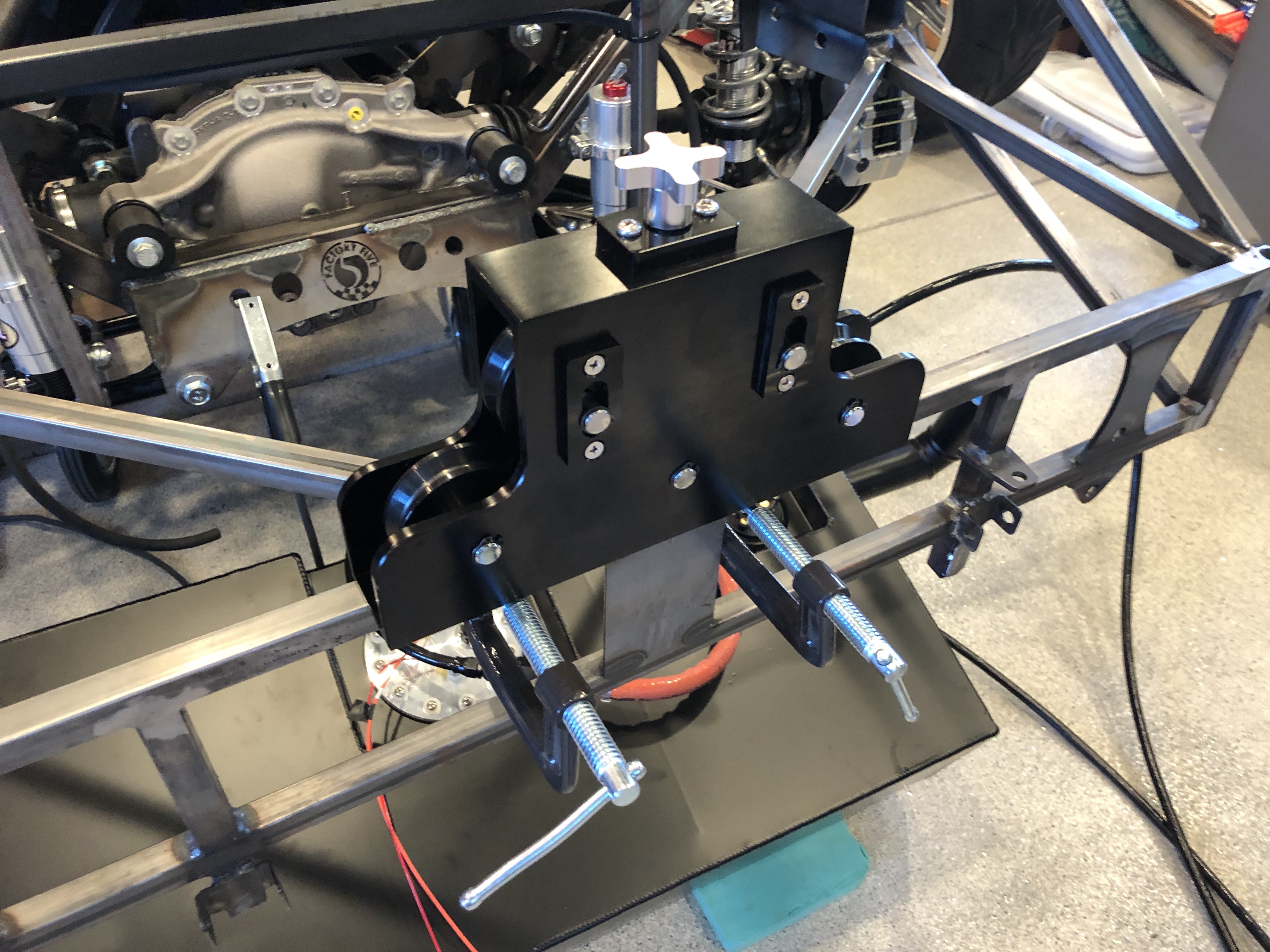
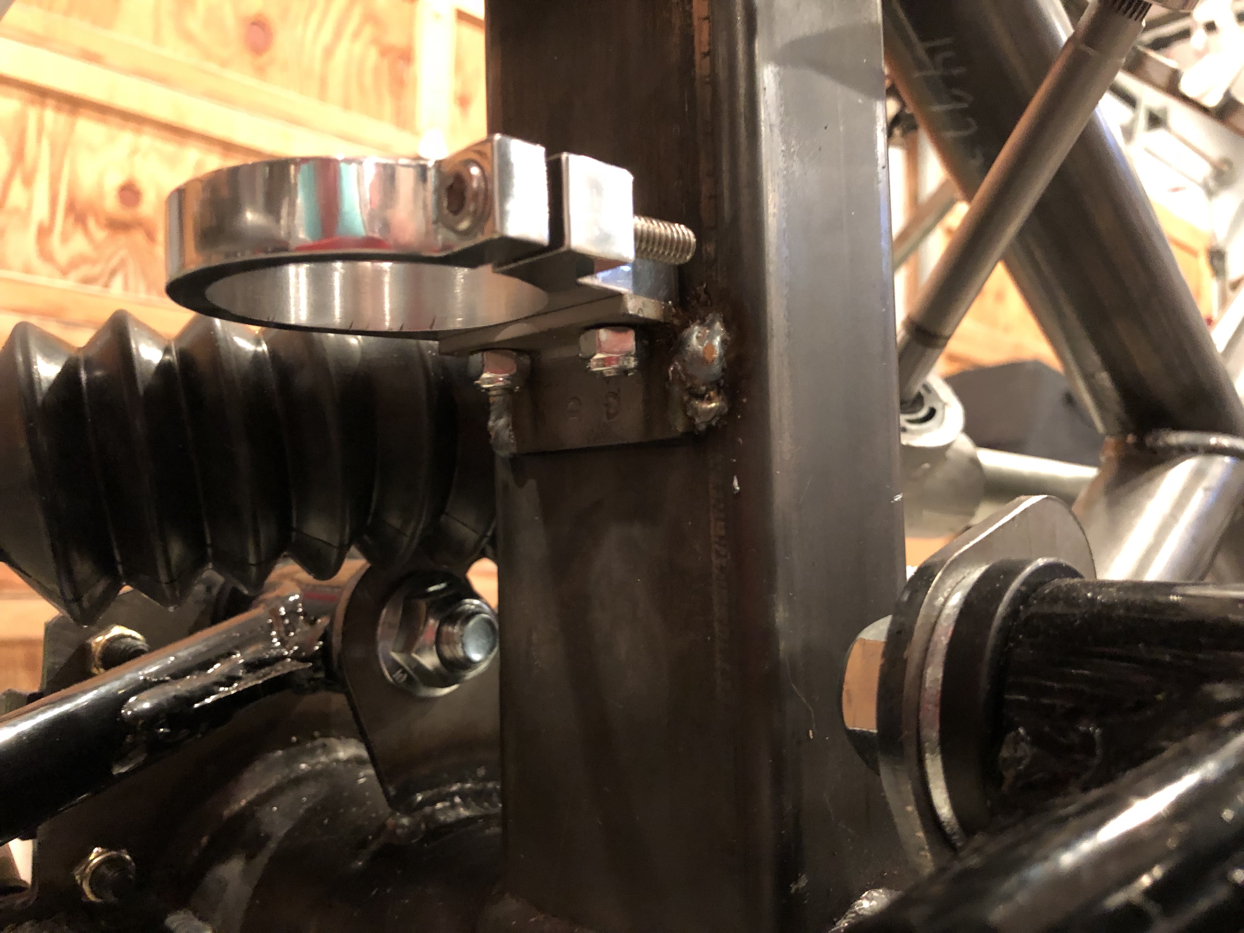
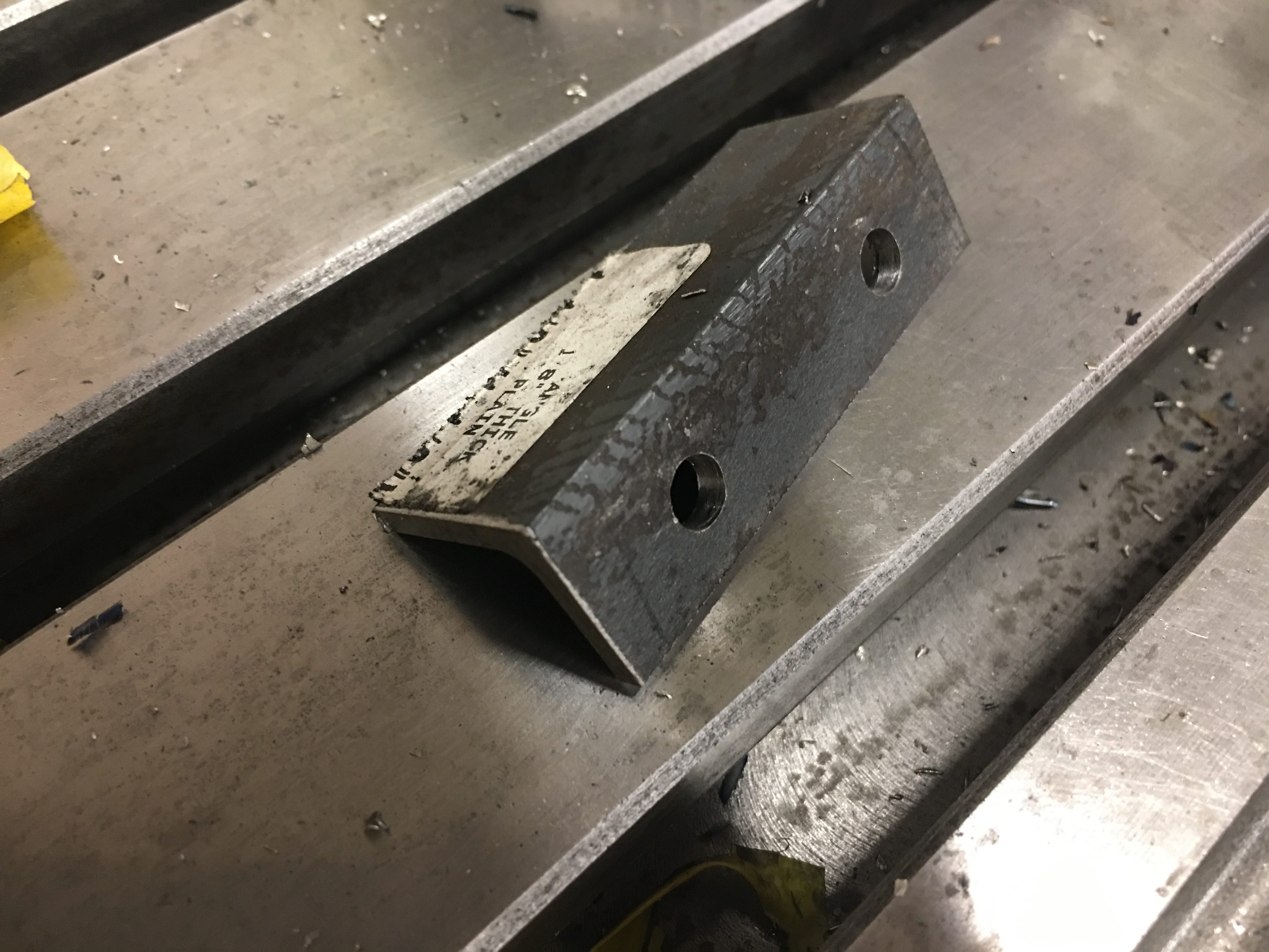
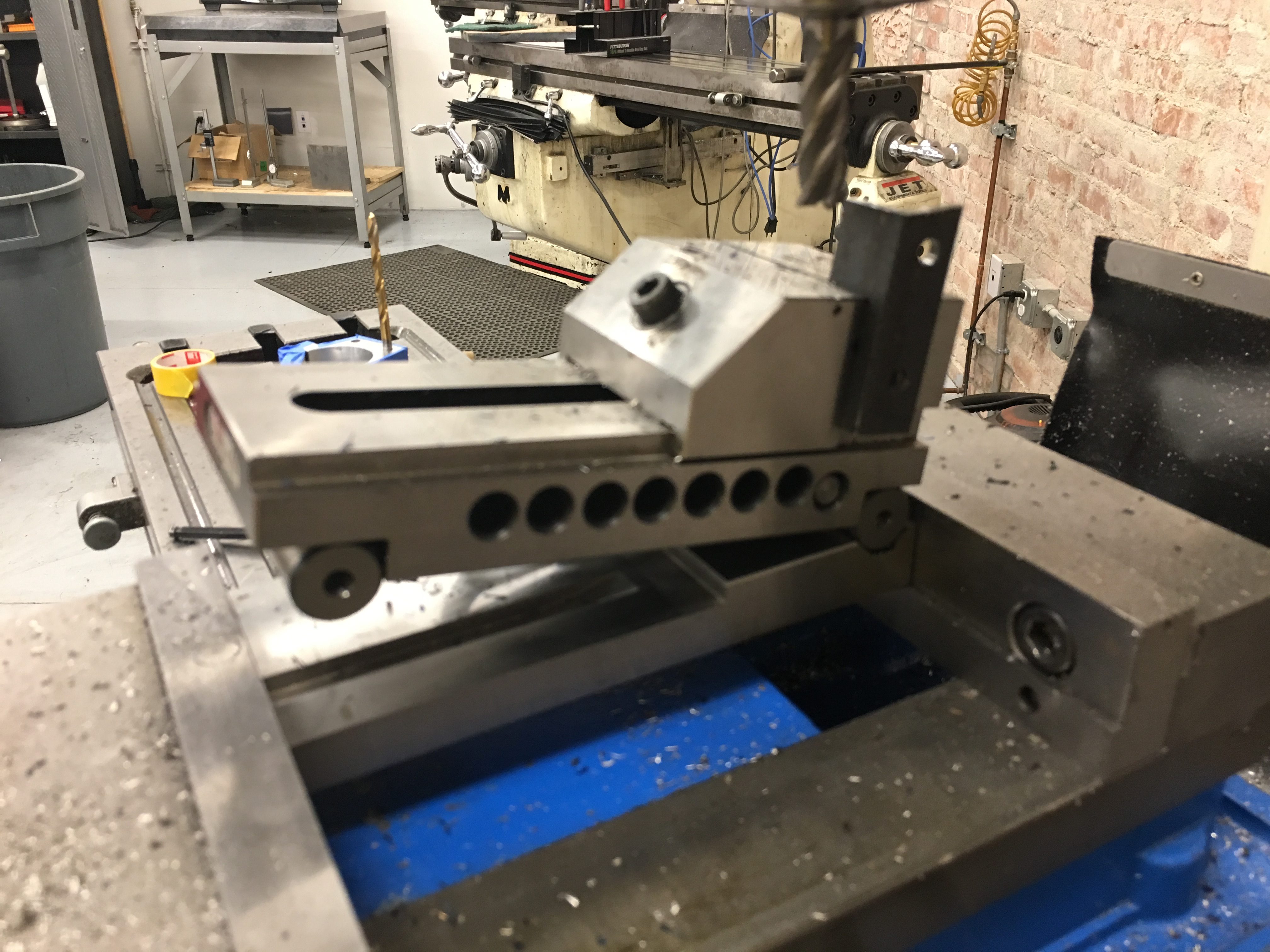
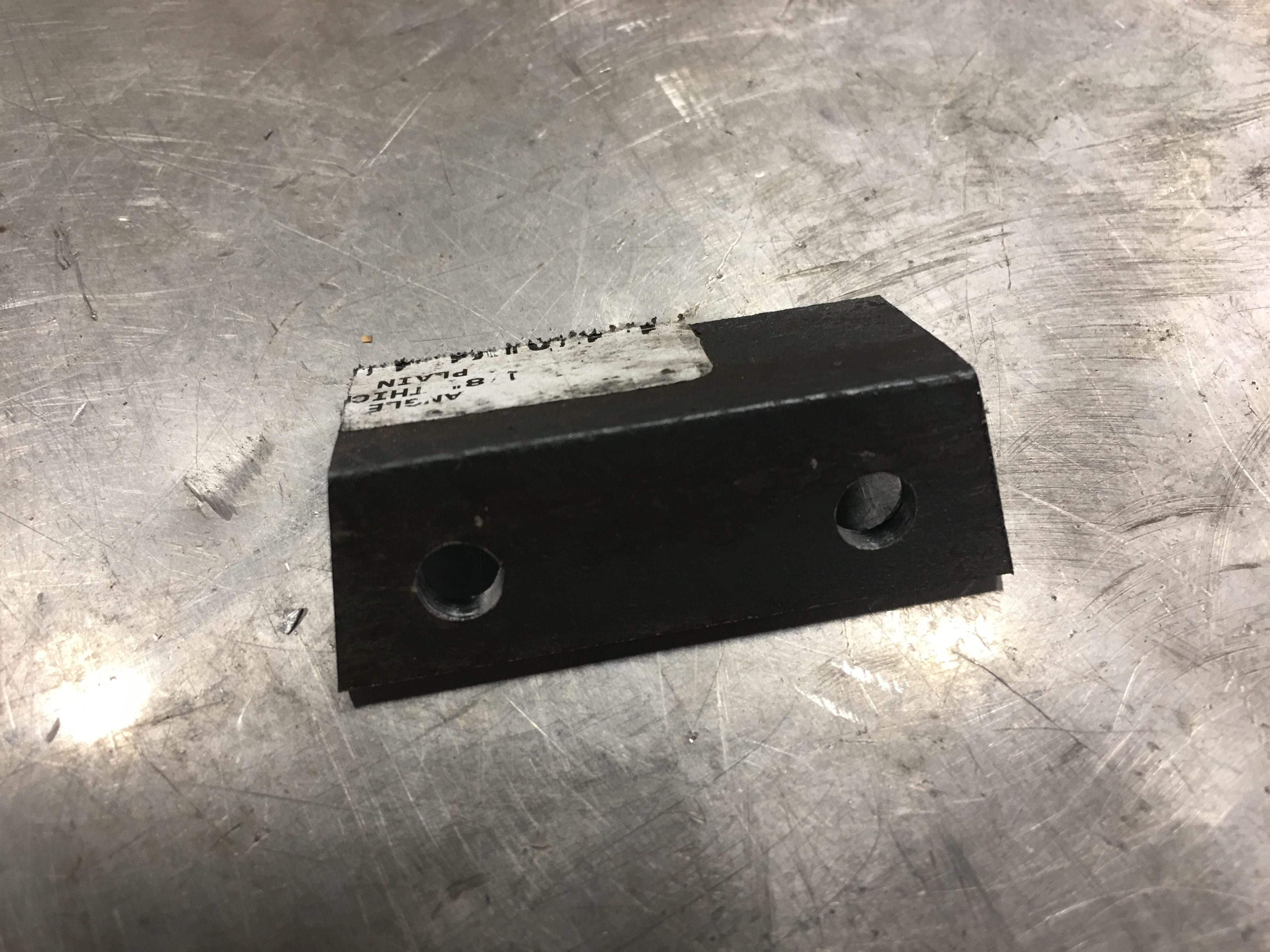
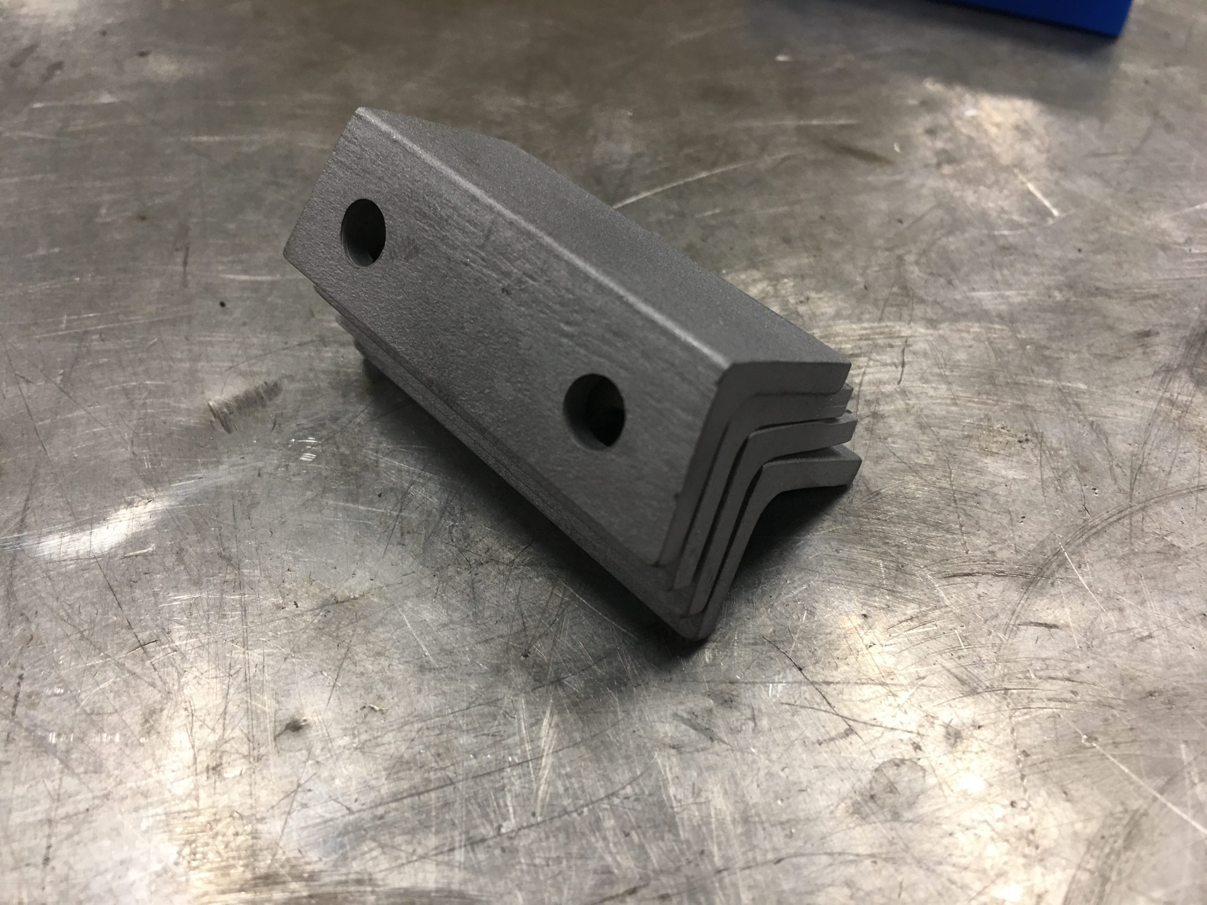
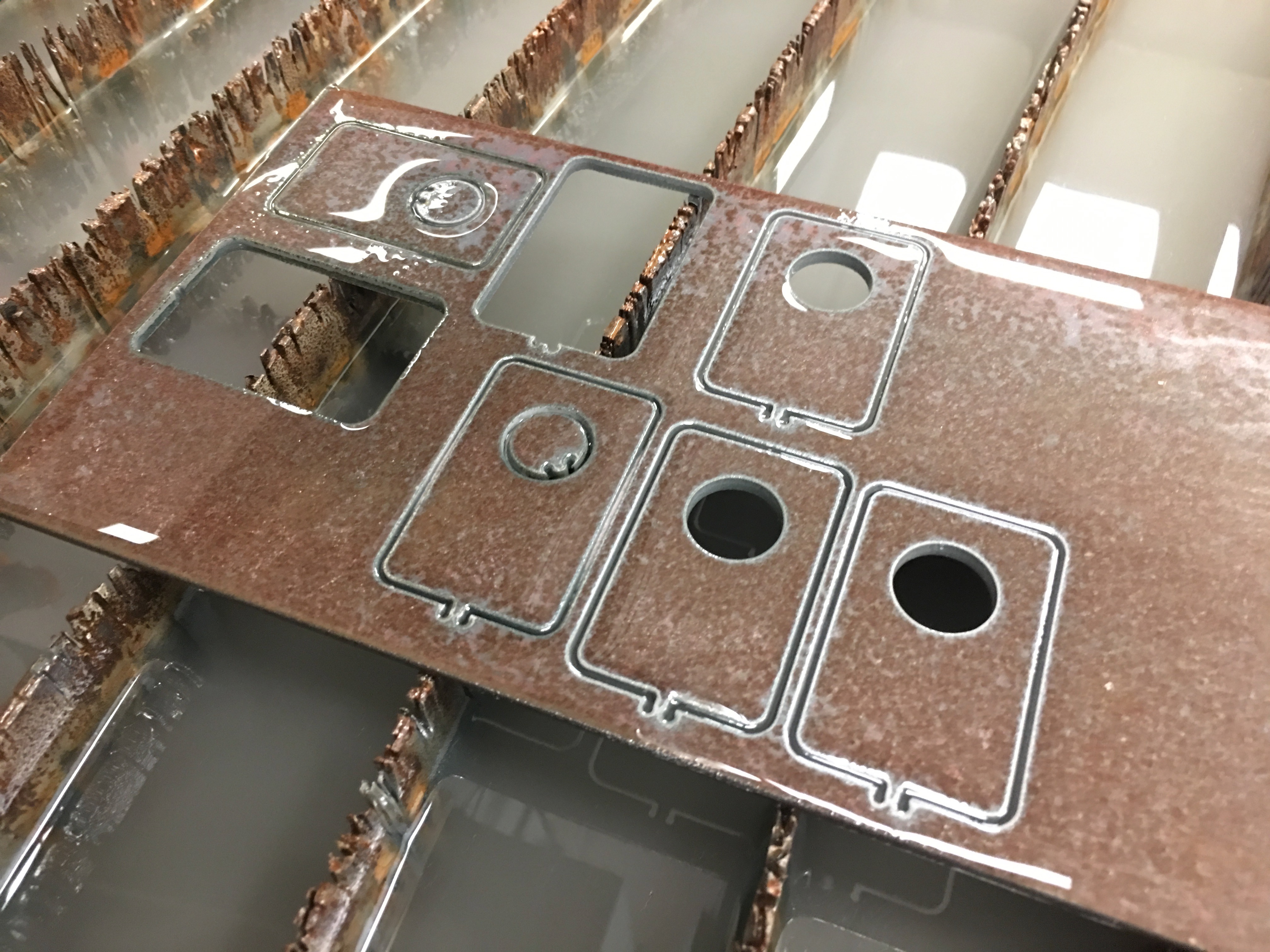
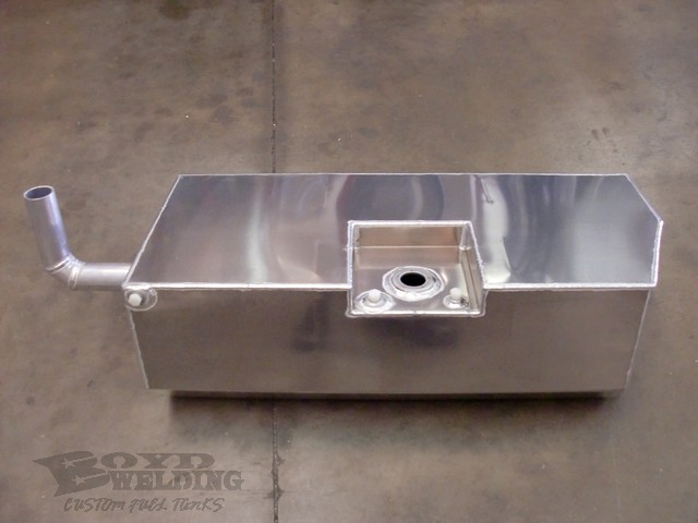
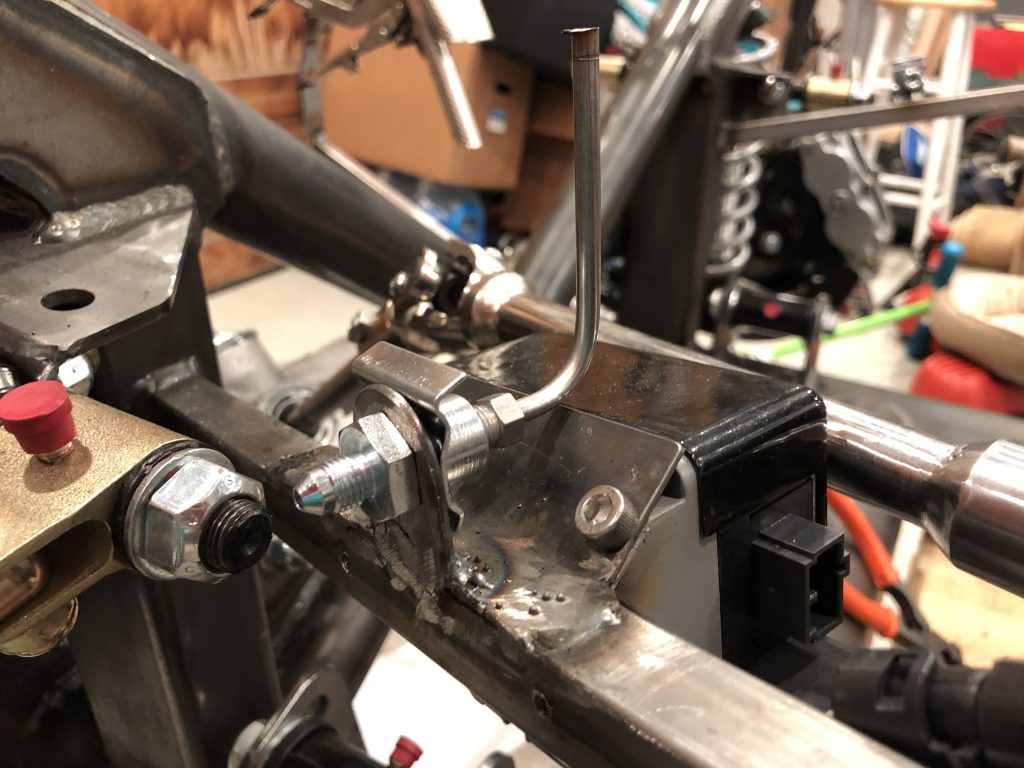
I installed the top and inside of the driver side foot box because I was considering installing the brake/clutch reservoir in the top of the foot box to ensure the bottom of the reservoirs were level with or higher than the inlet of the master cylinders. After some careful measurements, I determined I could install them in front of the foot box and meet this criteria. I quickly fabricated a bracket out of some 1/8″ steel plate I had and welded it to the chassis tube.

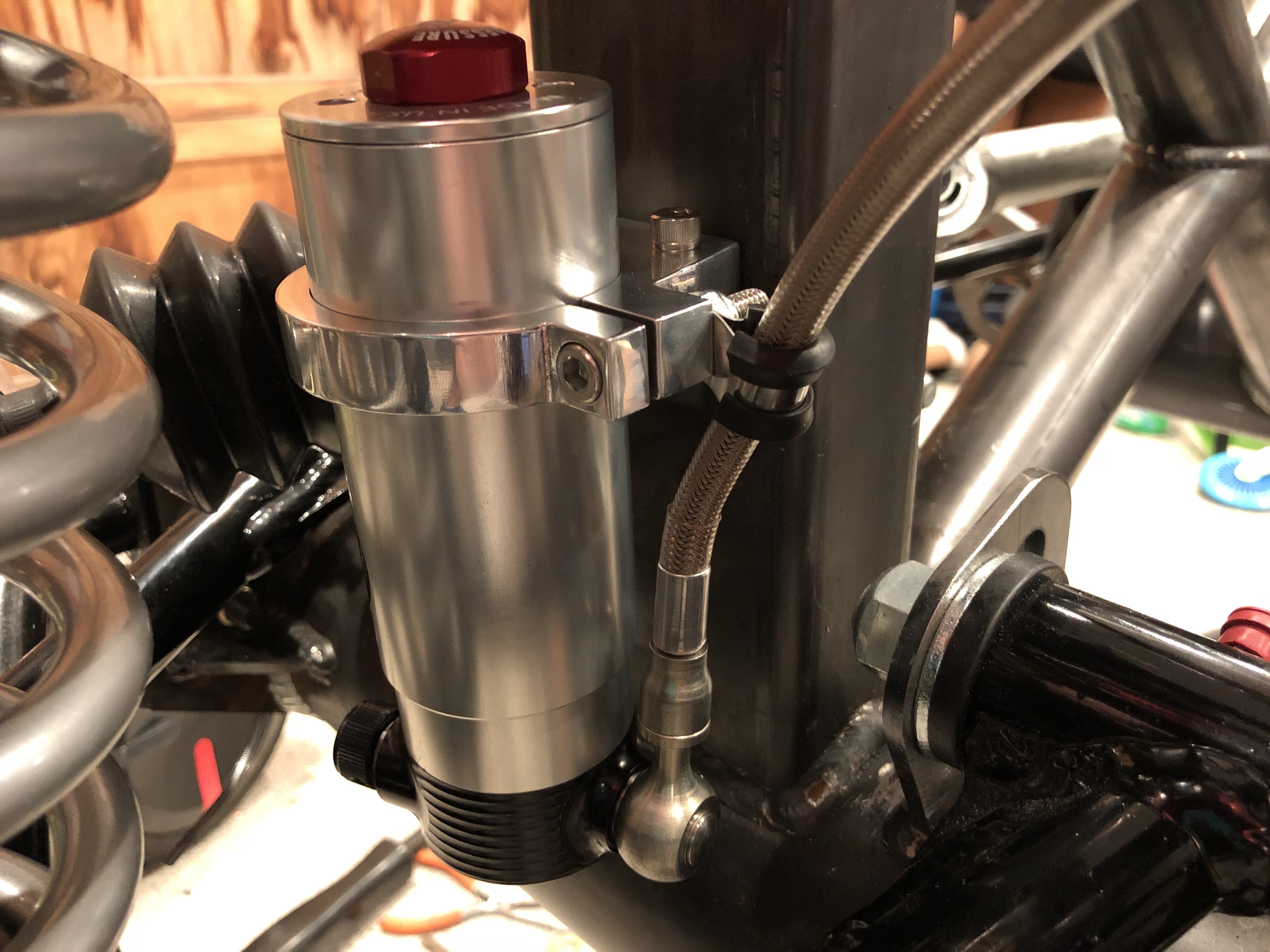
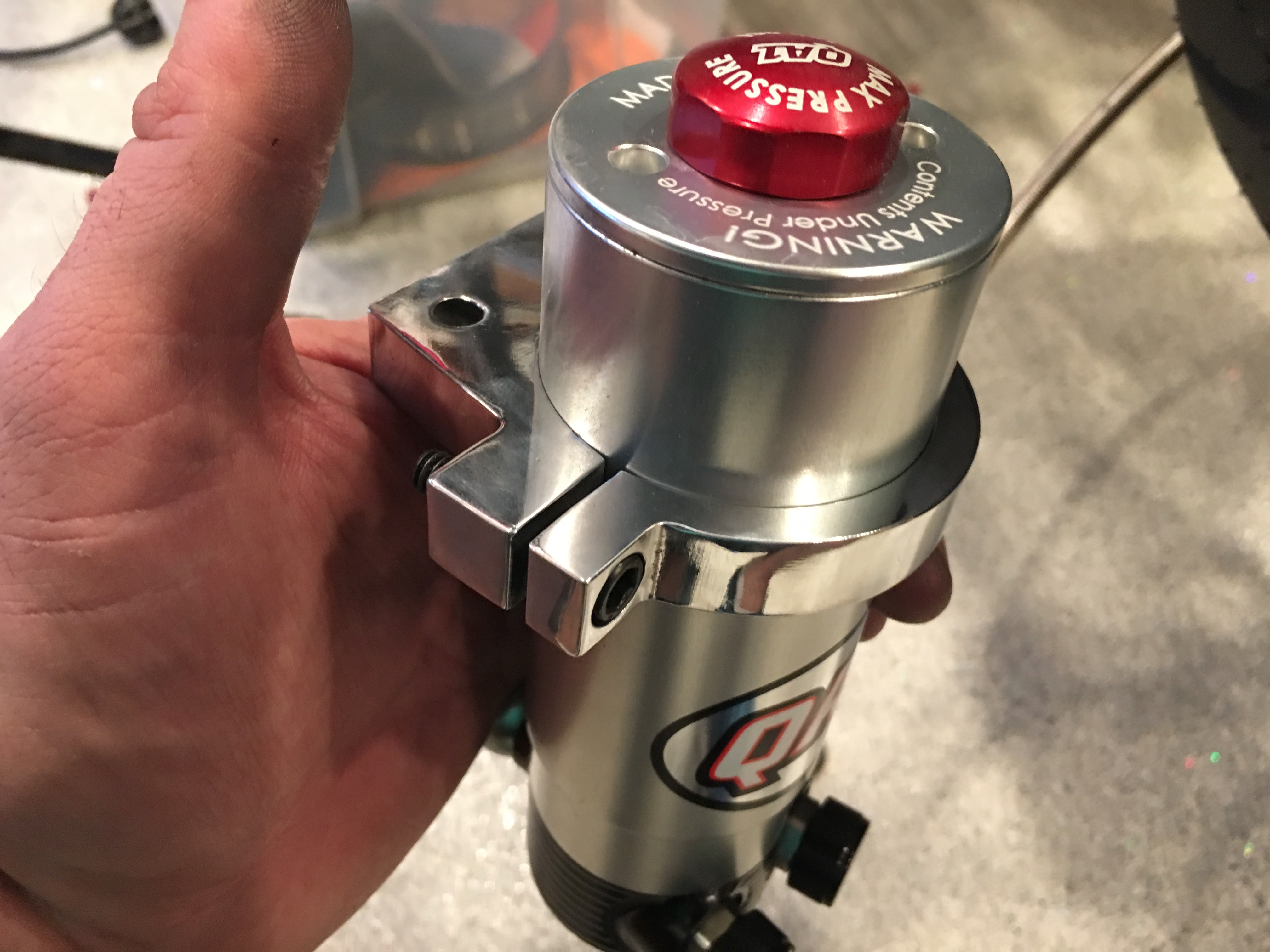
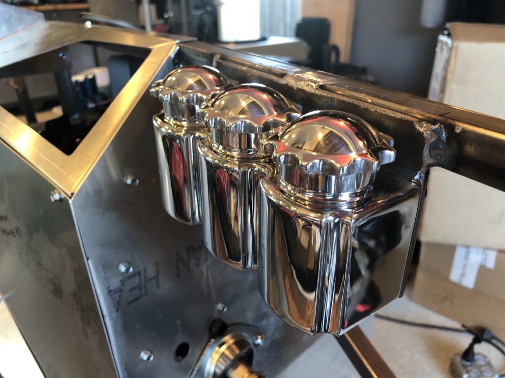
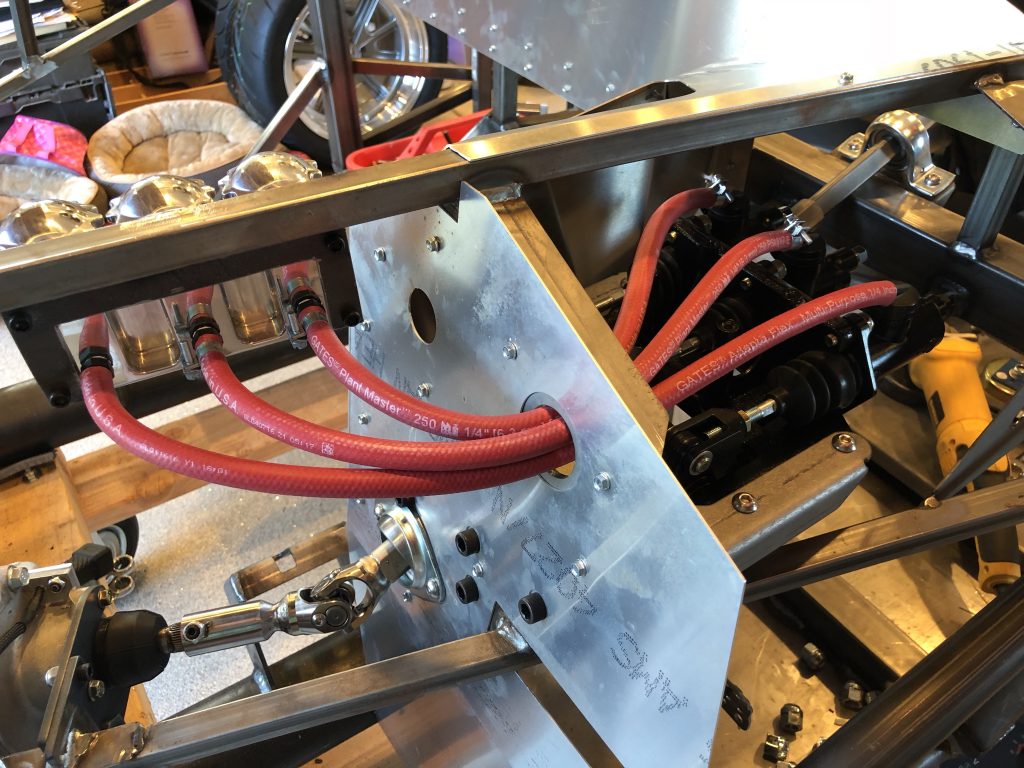
The triple reservoir bolts to this bracket through the holes visible above. The tops of the caps are even with the top of the chassis tube. I went with a triple reservoir so that there are separate reservoirs for the front and back brakes for redundancy. The left two reservoirs are for the brakes; the right is for the clutch.

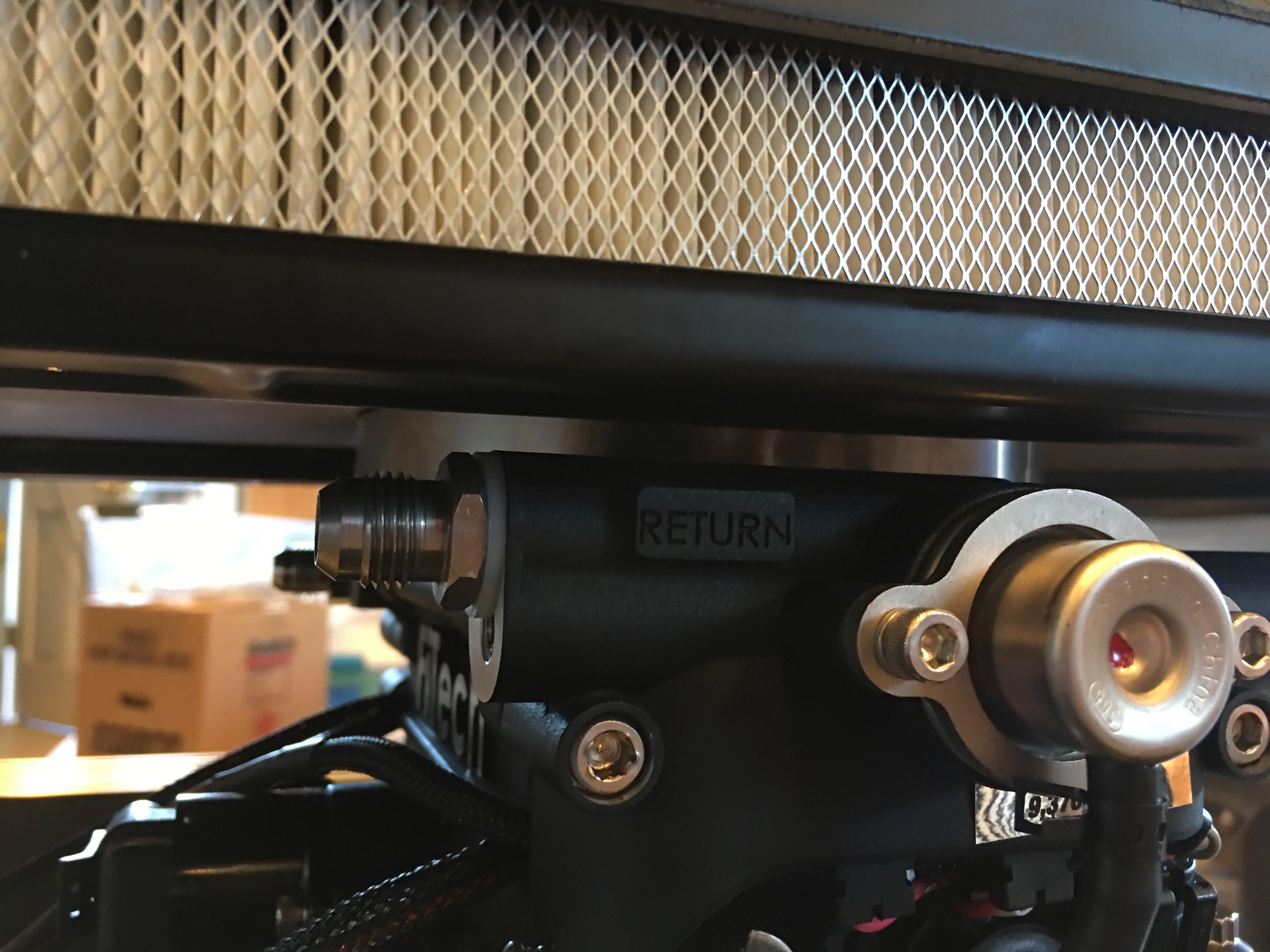
I connected the reservoirs to the master cylinders with some EPDM tubing. I didn’t have enough hose clamps to finish this, but I have more on order.

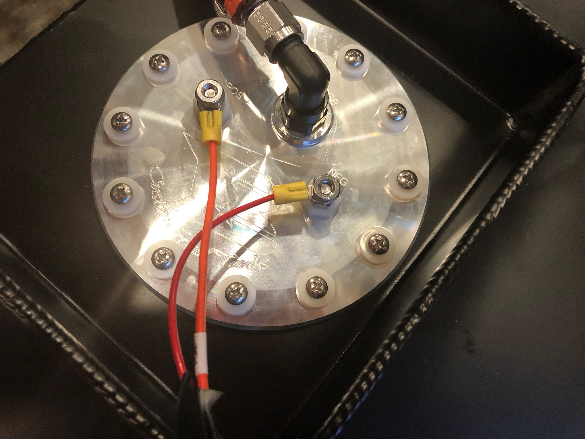
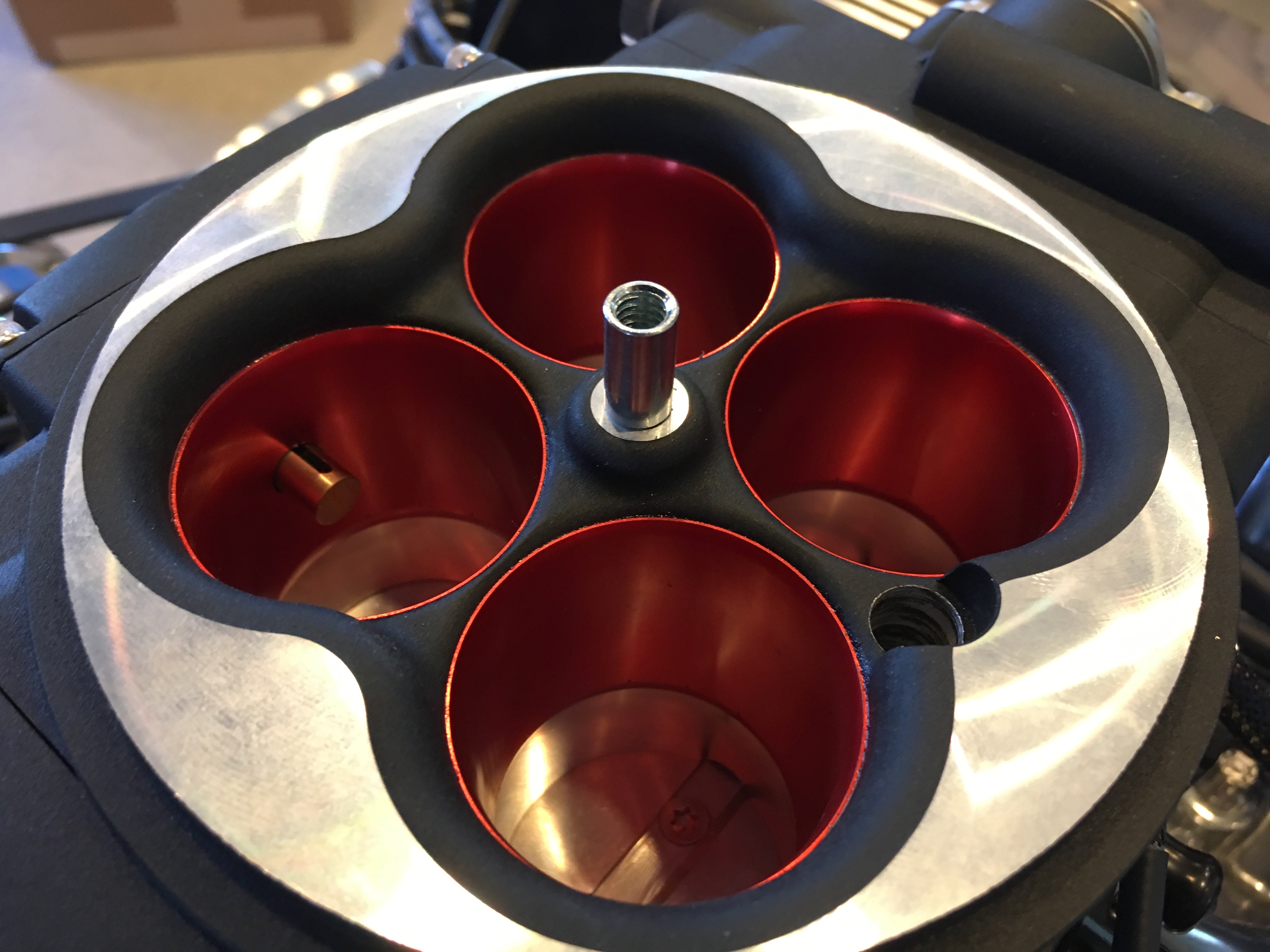
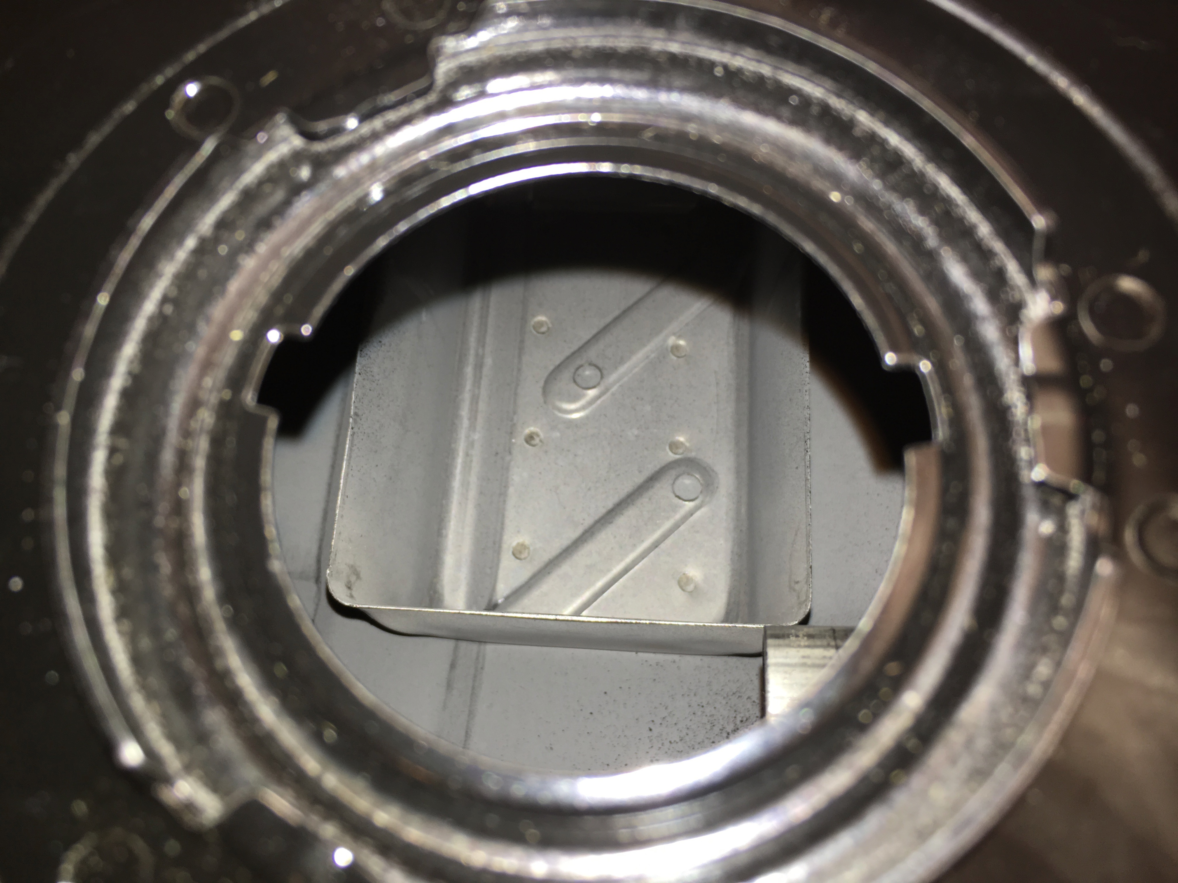
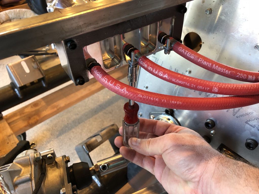
I’ve been trying to make sure that everything is accessible for future maintenance. Although access is easy now, with the body on, the only way to access these screws is from below.

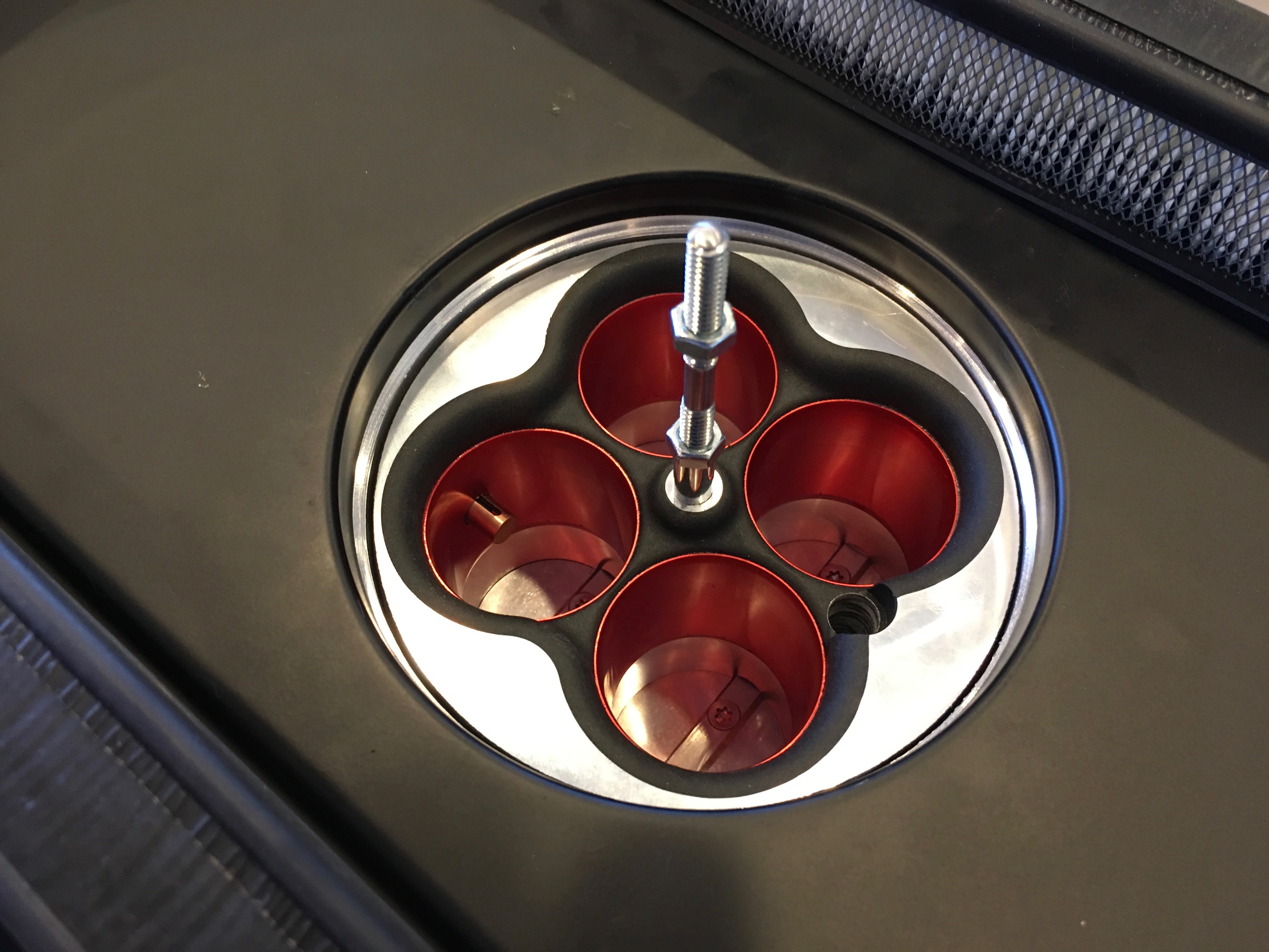
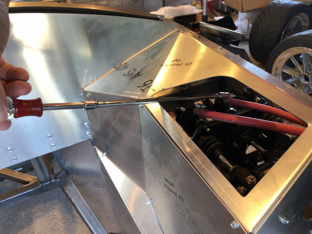
I did the same thing with the hose clamps in the foot box. With the body on and the foot box riveted in place, the only access with either be from below or through this hole. I made sure I could access all of the hose clamps from above before tightening everything down.

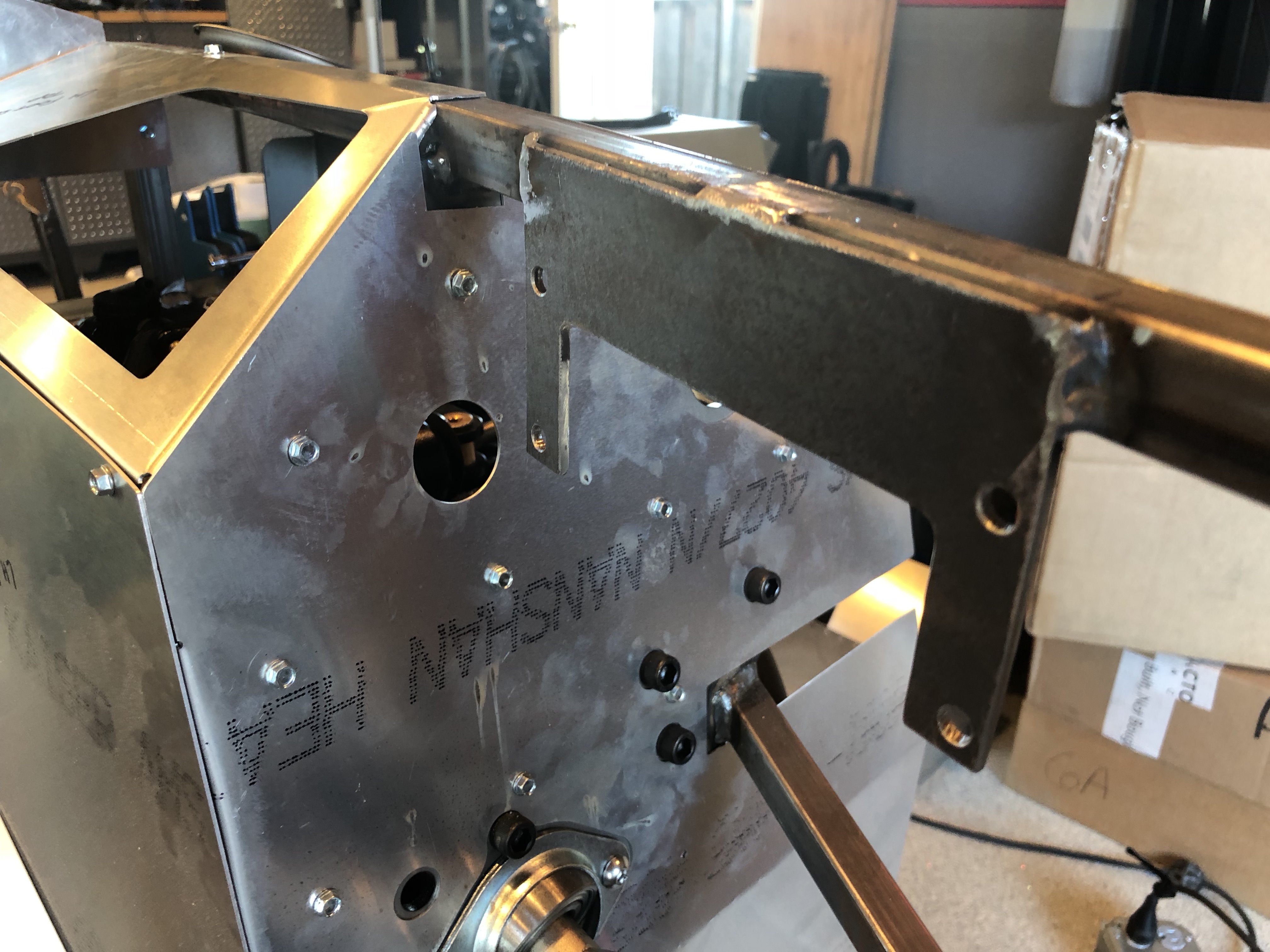
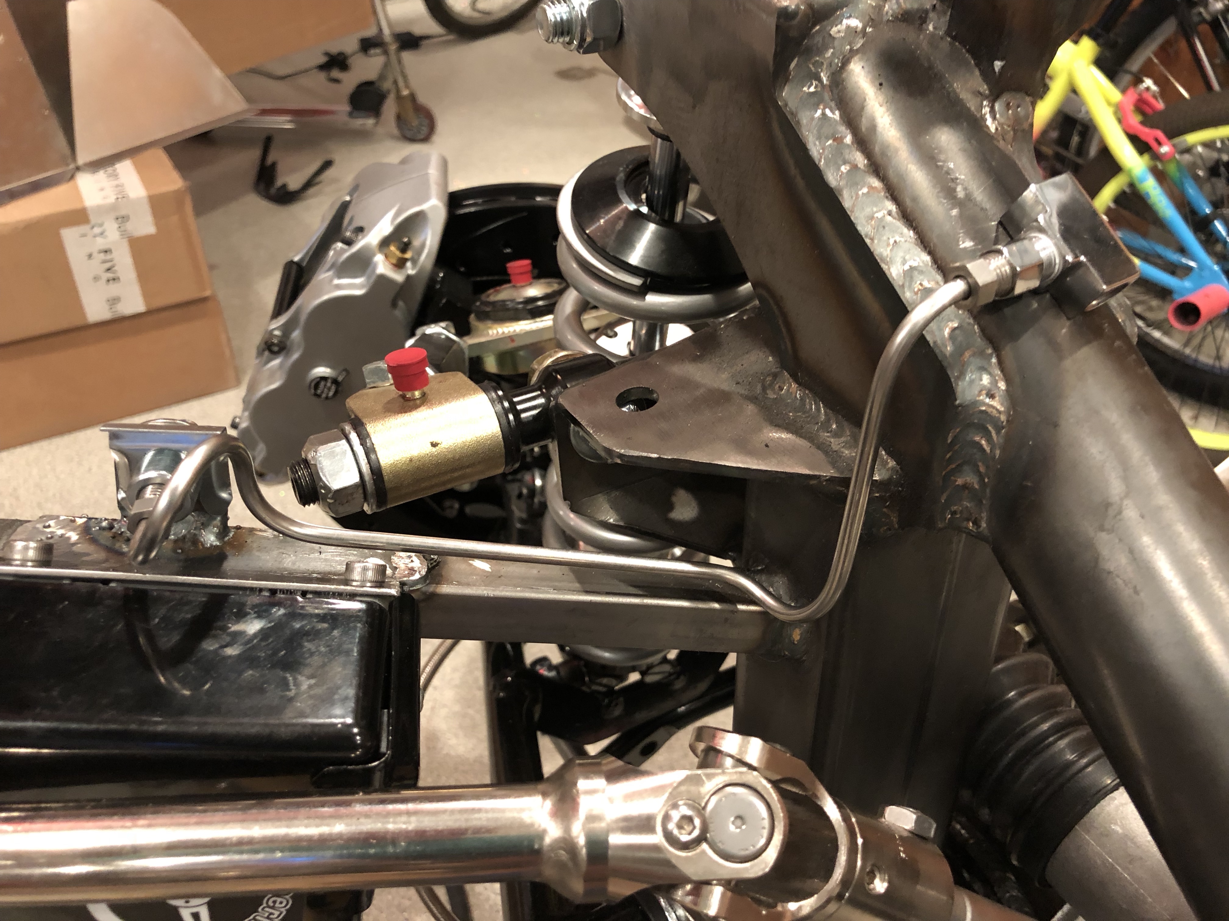
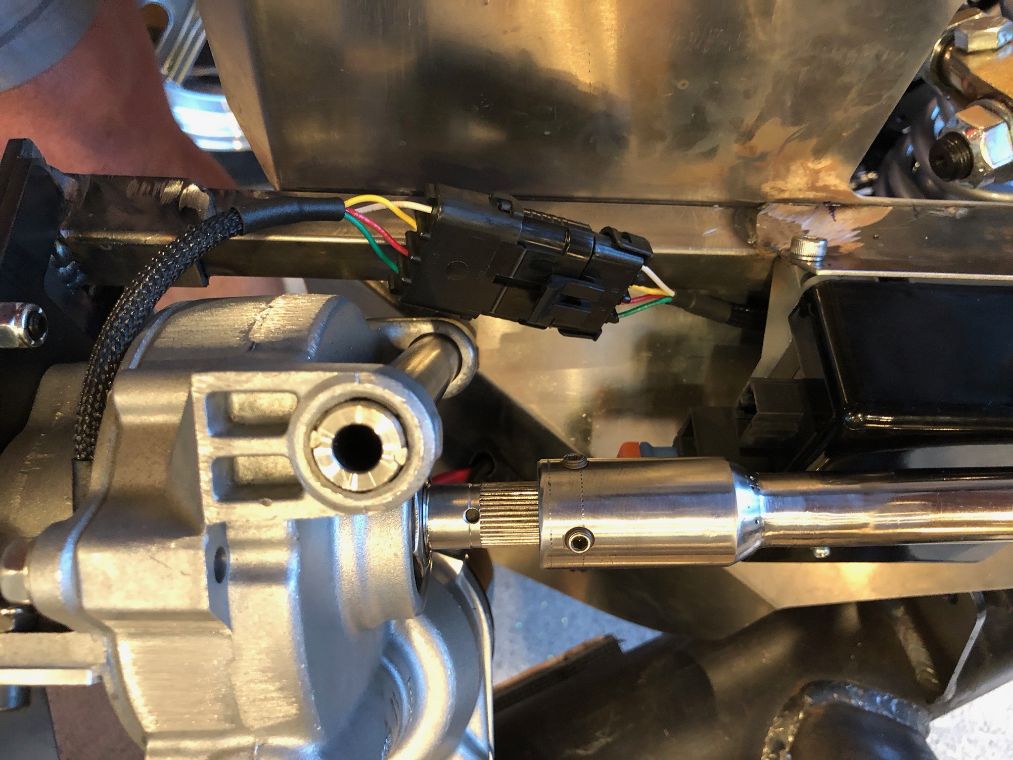
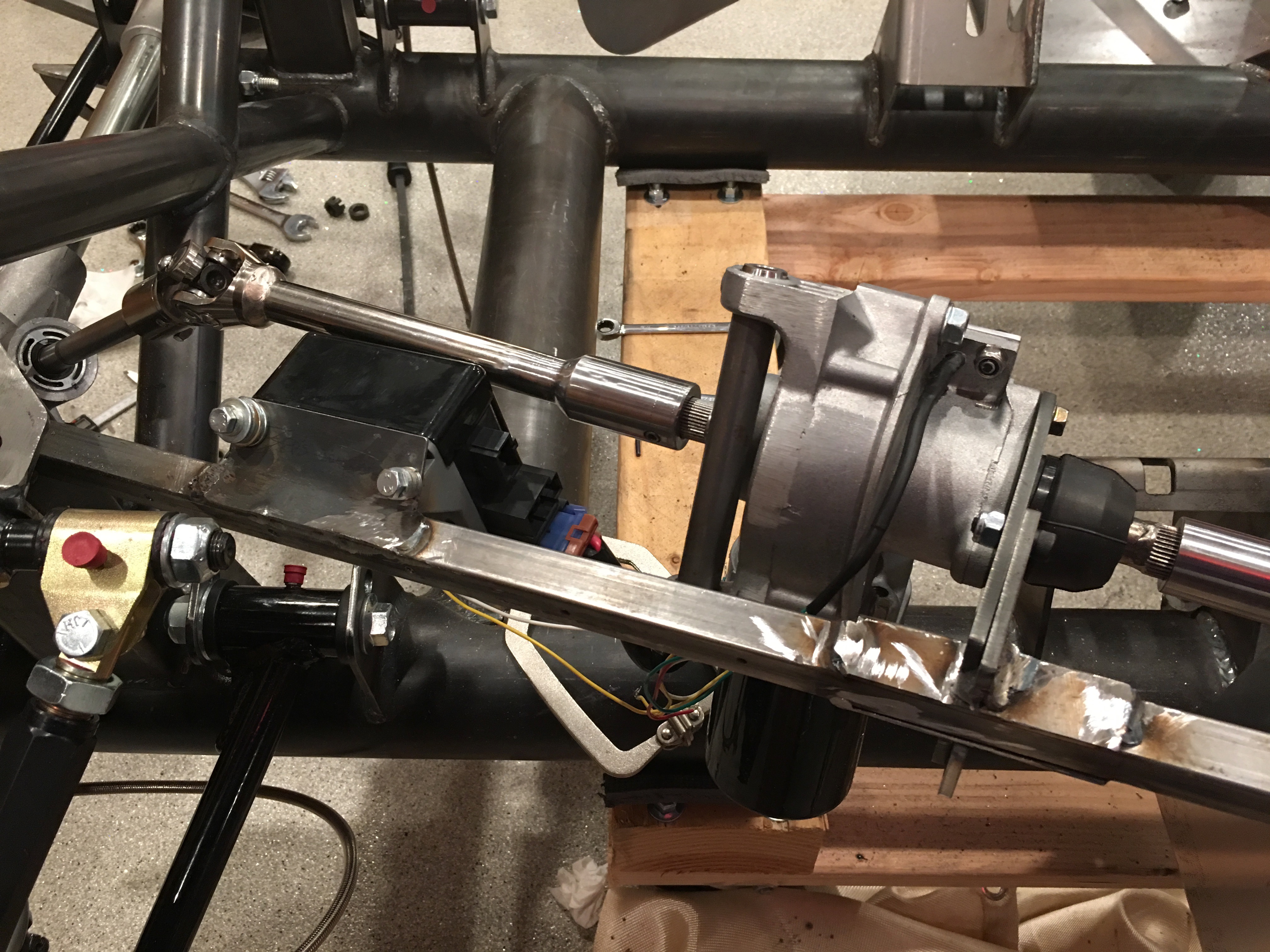
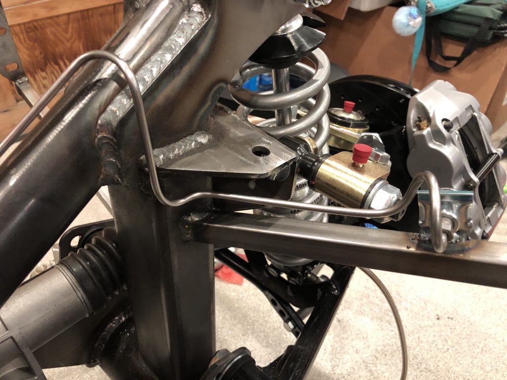
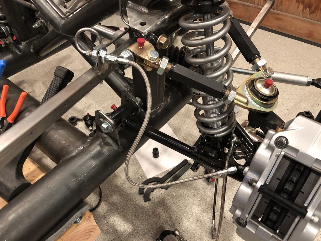
With the reservoir and master cylinder plumbing complete, I continued fabricating the hard lines. I welded on the front tabs near the aft end of the holes in the F panels. I’ll finish cleaning up the welds before the chassis is finished.

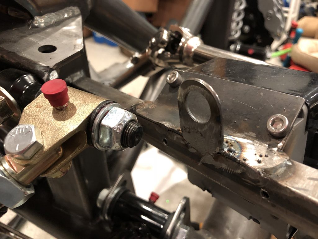
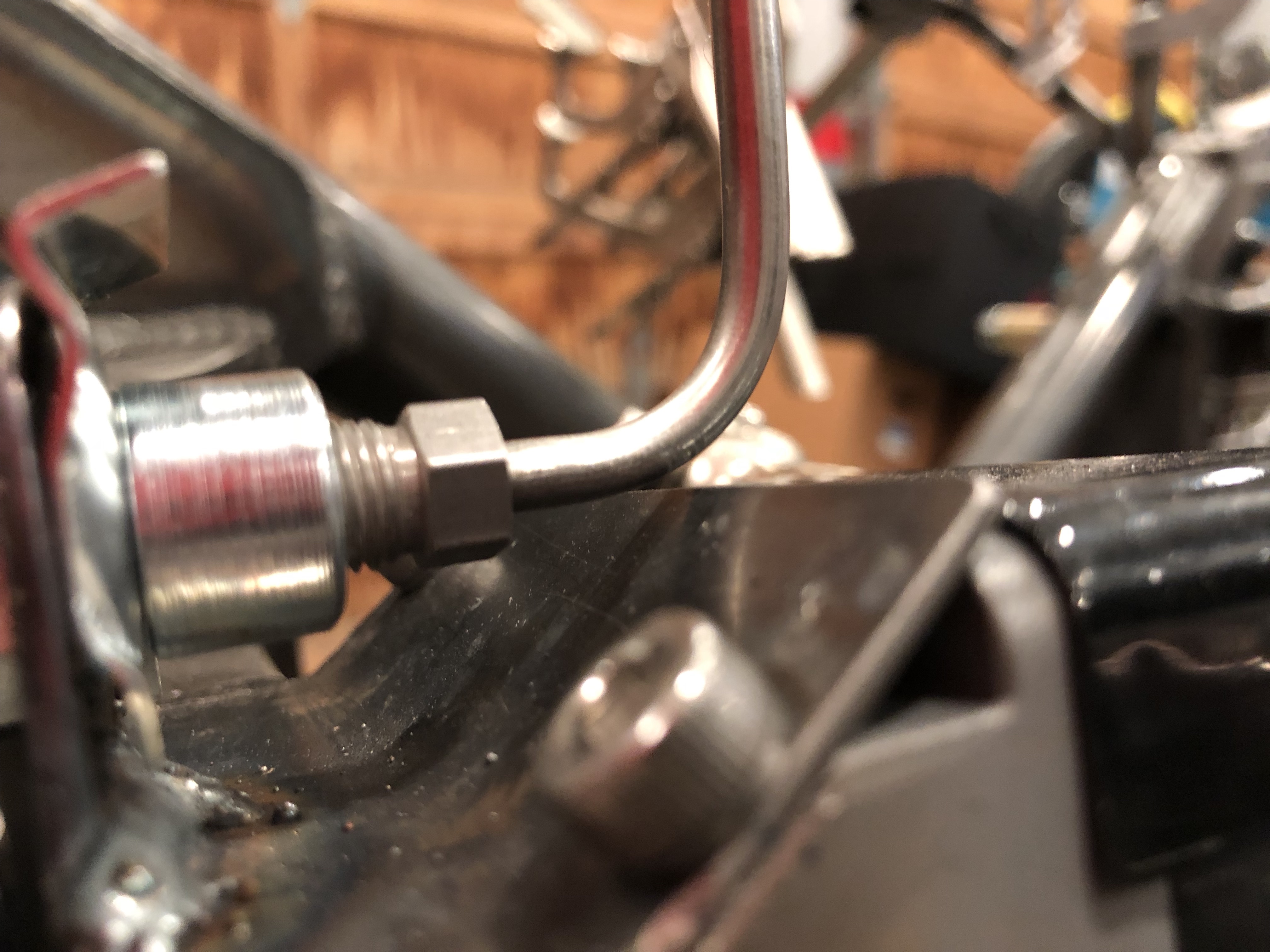
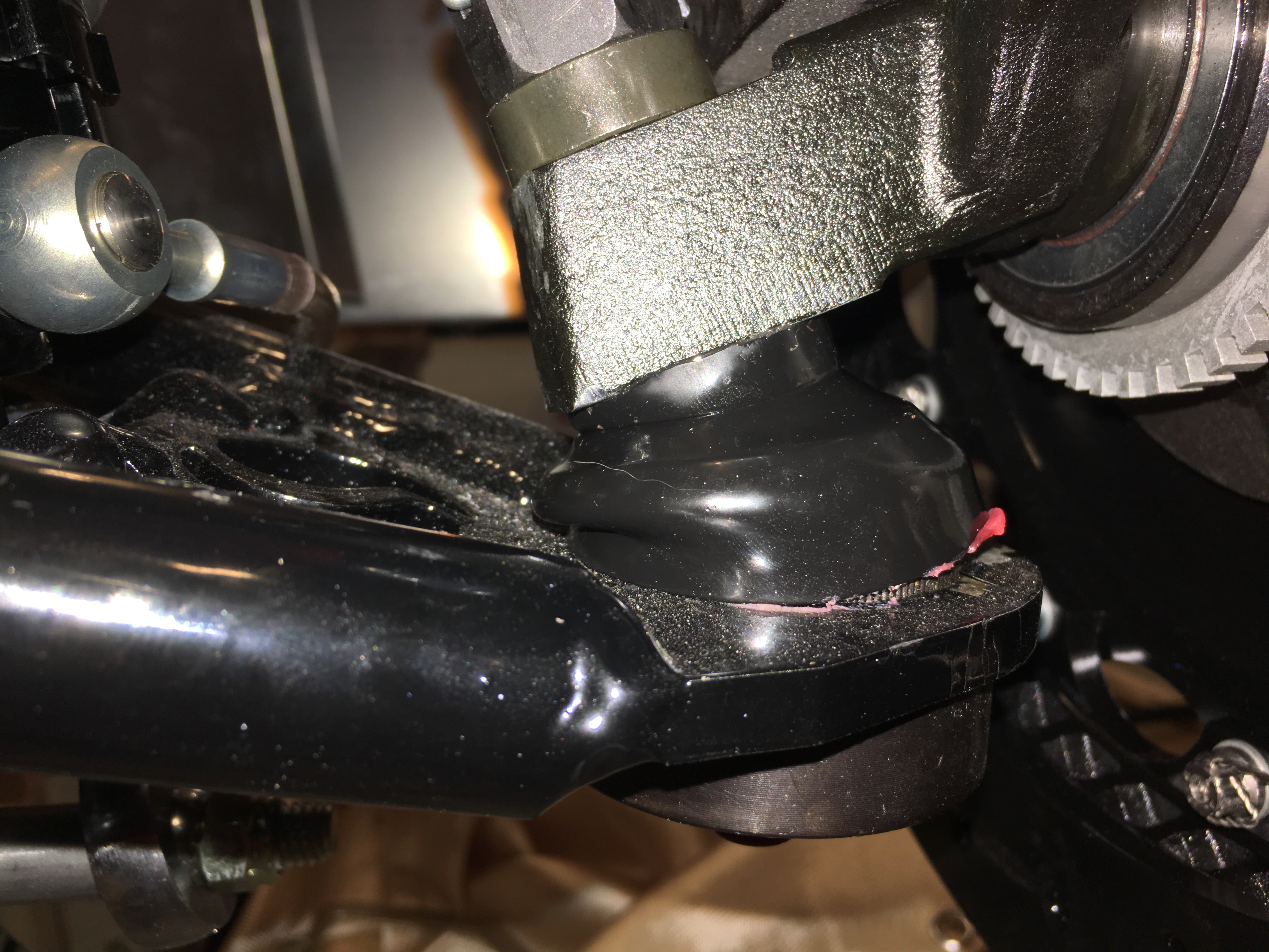
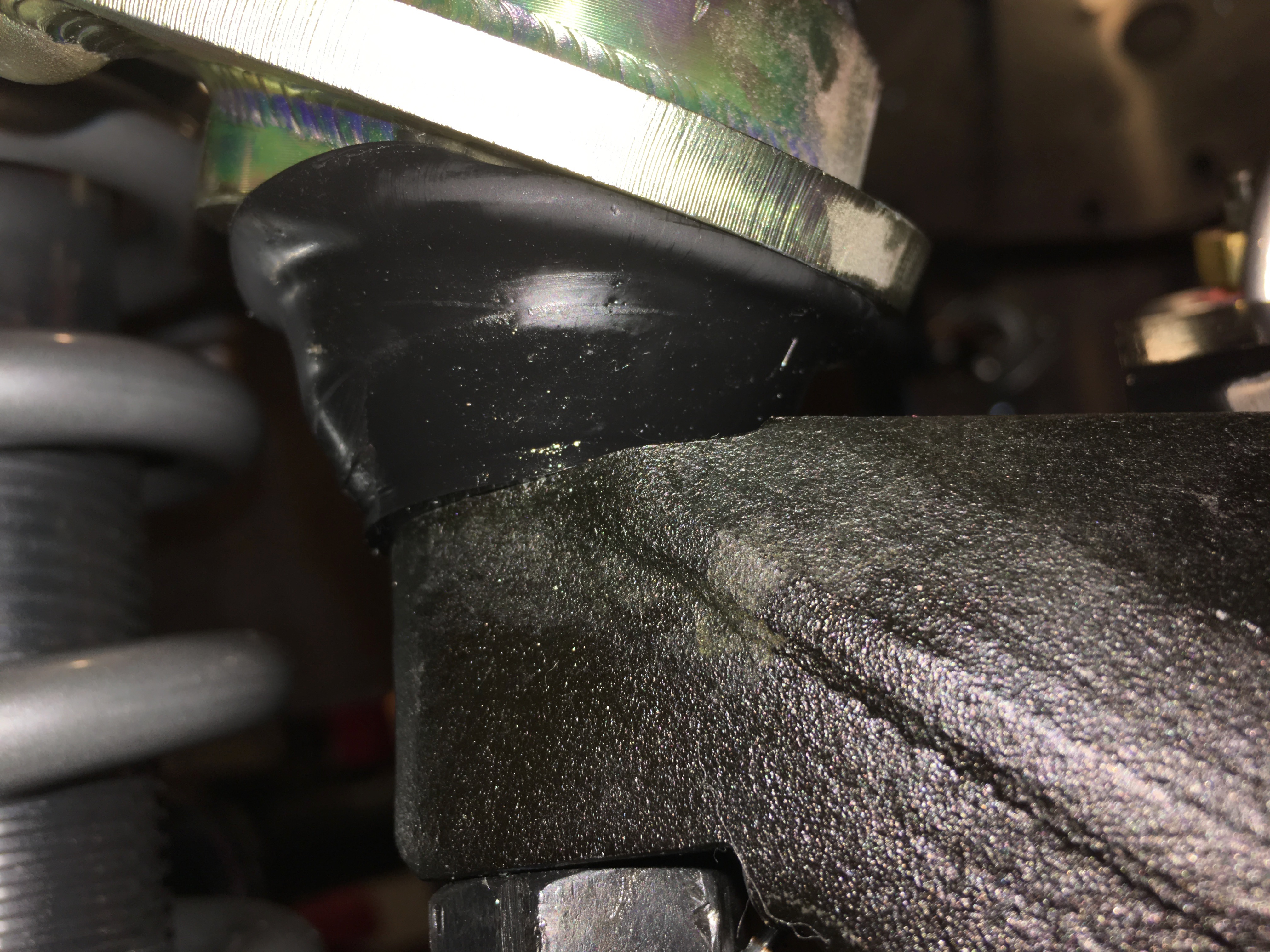
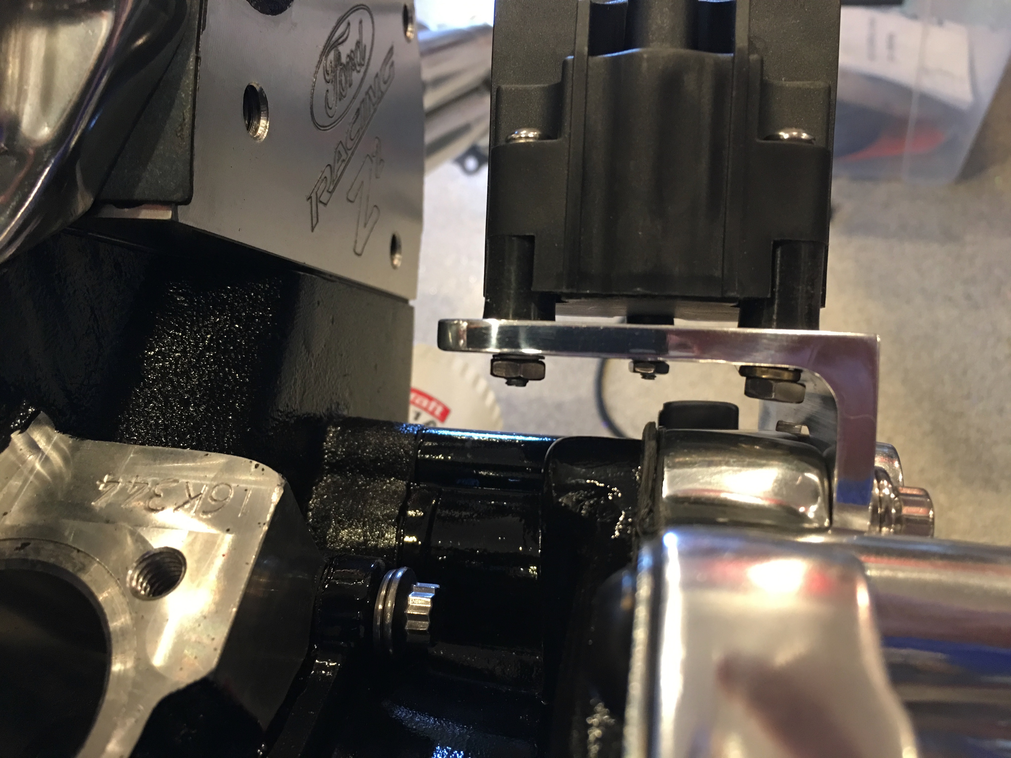
With the tab welded in place, I wanted to make sure that the brake line didn’t contact theelectric power steering support.

Fortunately, I got lucky and there’s about 1/8″ of clearance here.

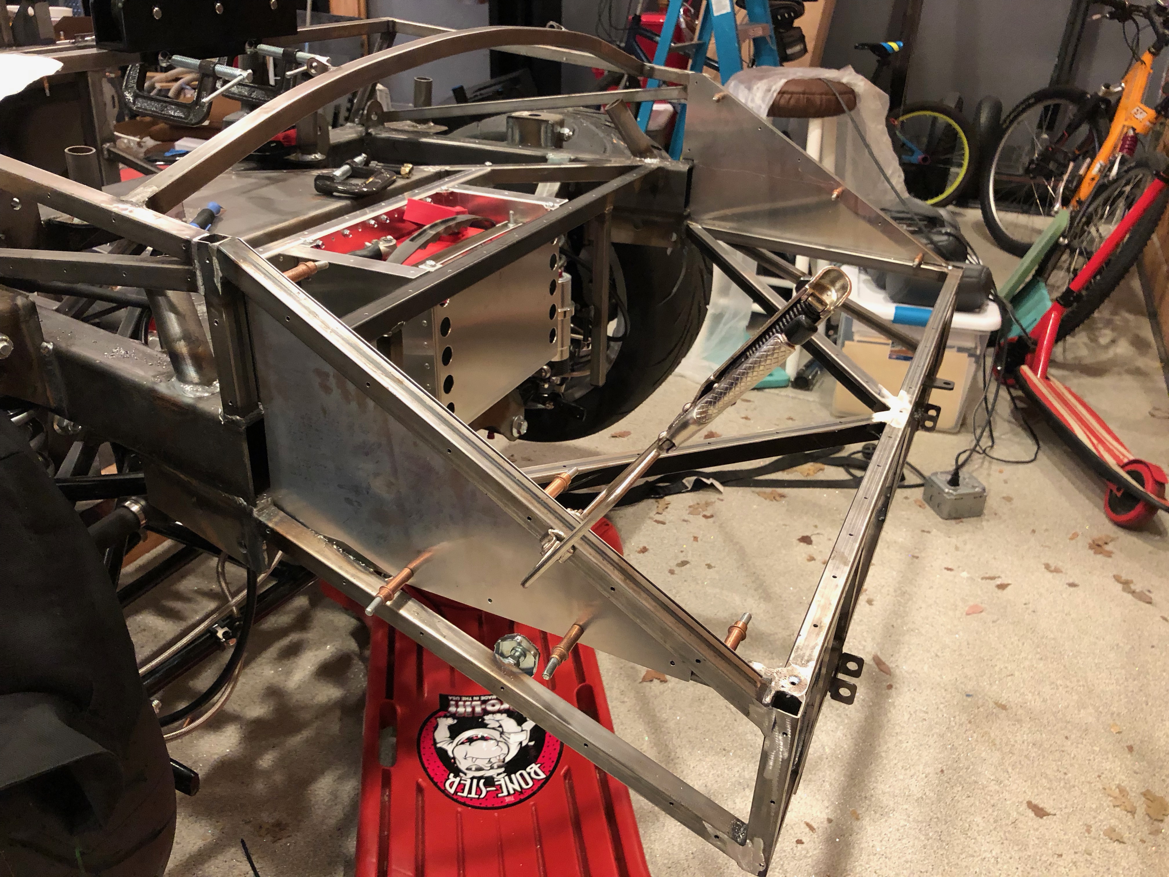
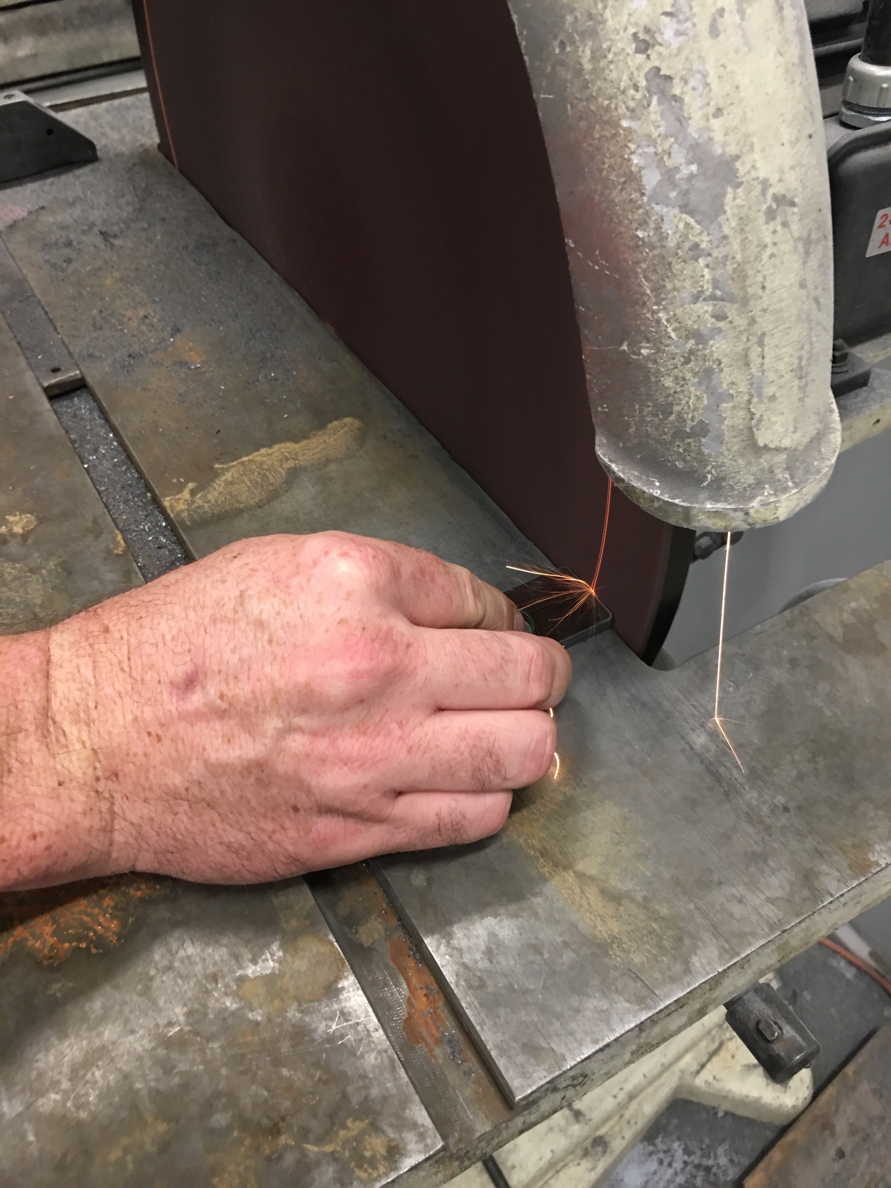
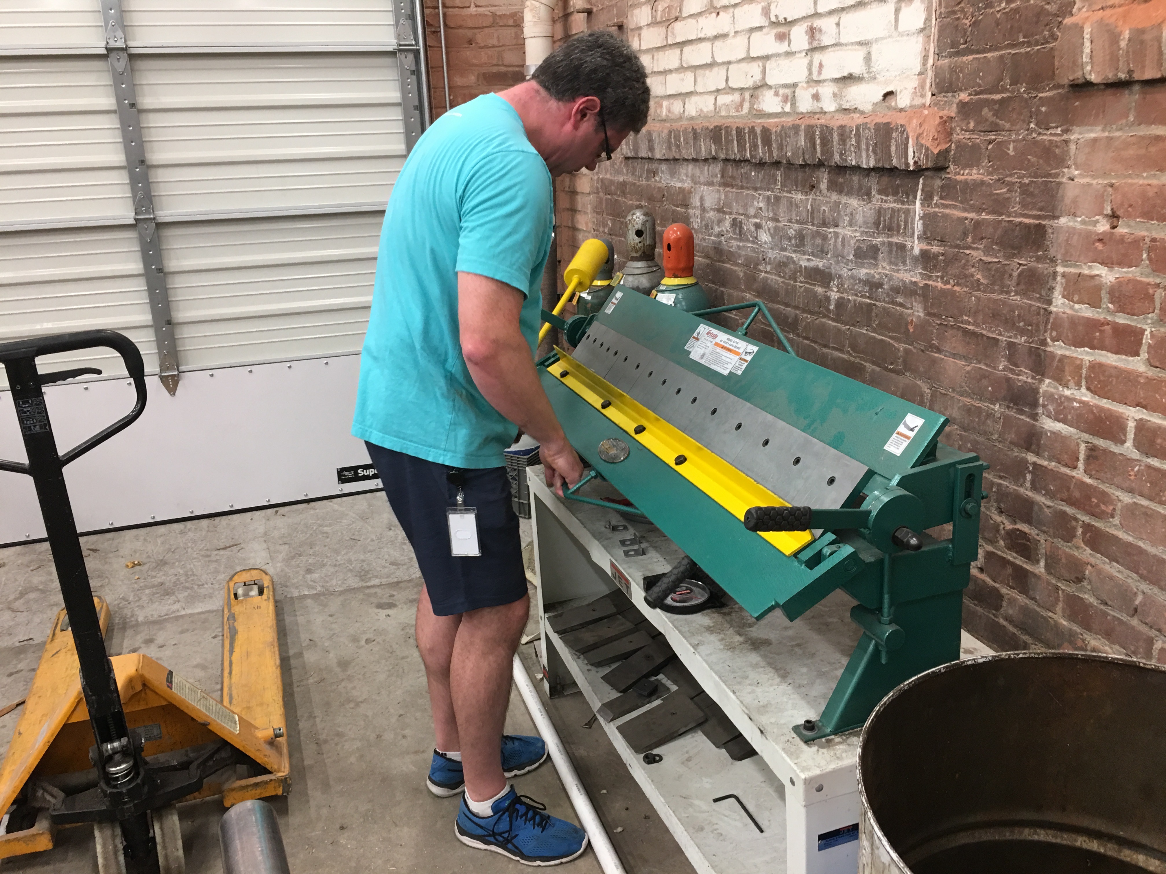
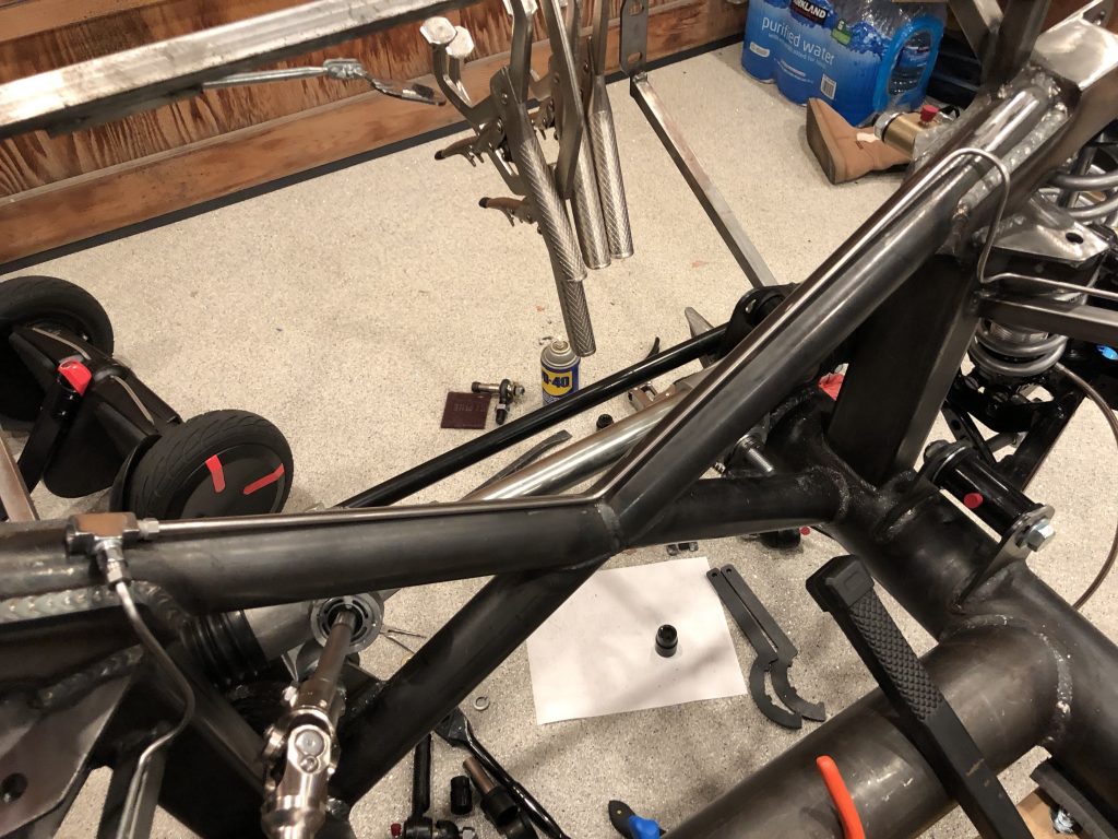
I clamped the tubing straightener to the aft end of the chassis so that I could straighten out some pieces of stainless brake tubing.

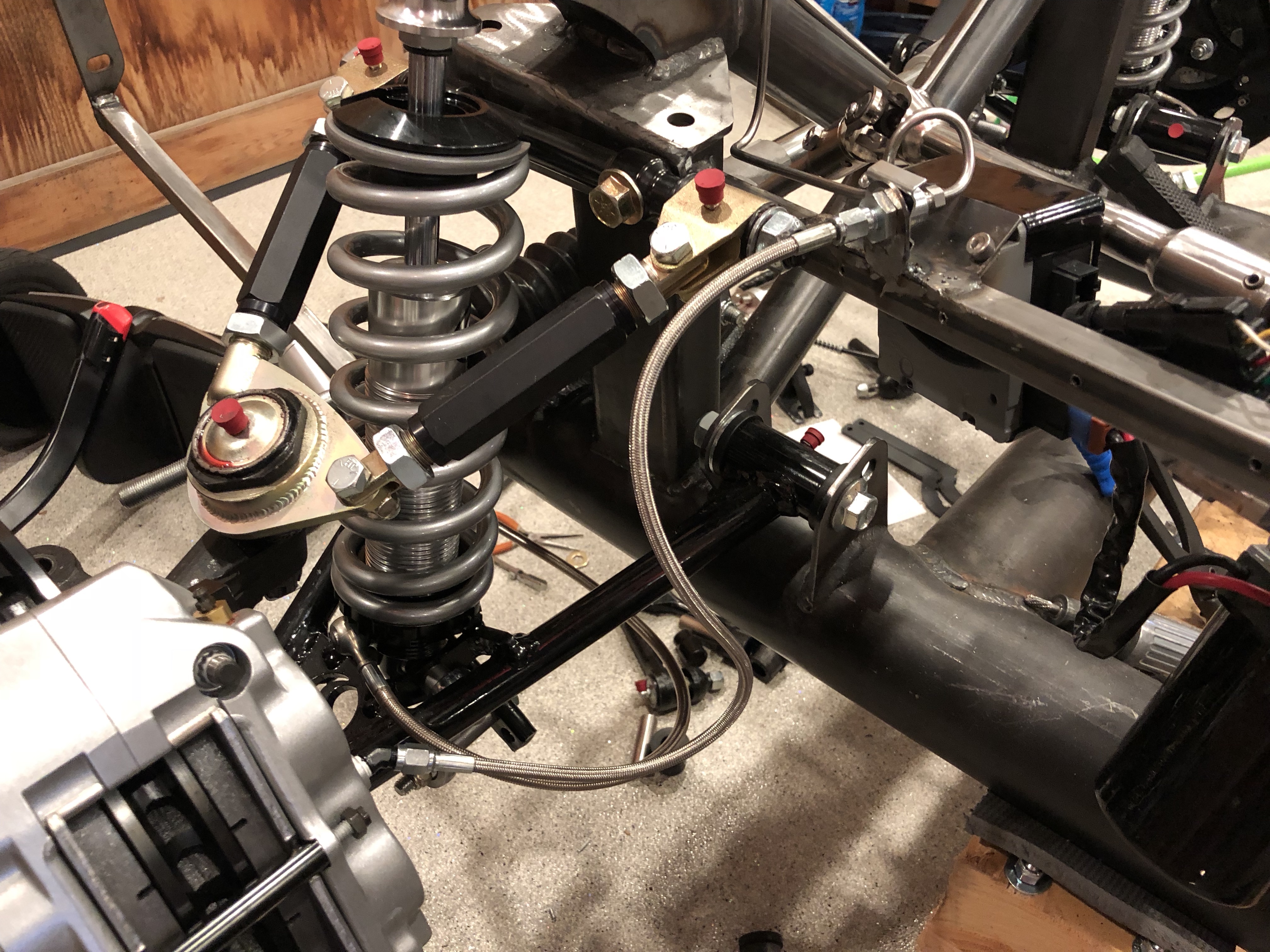
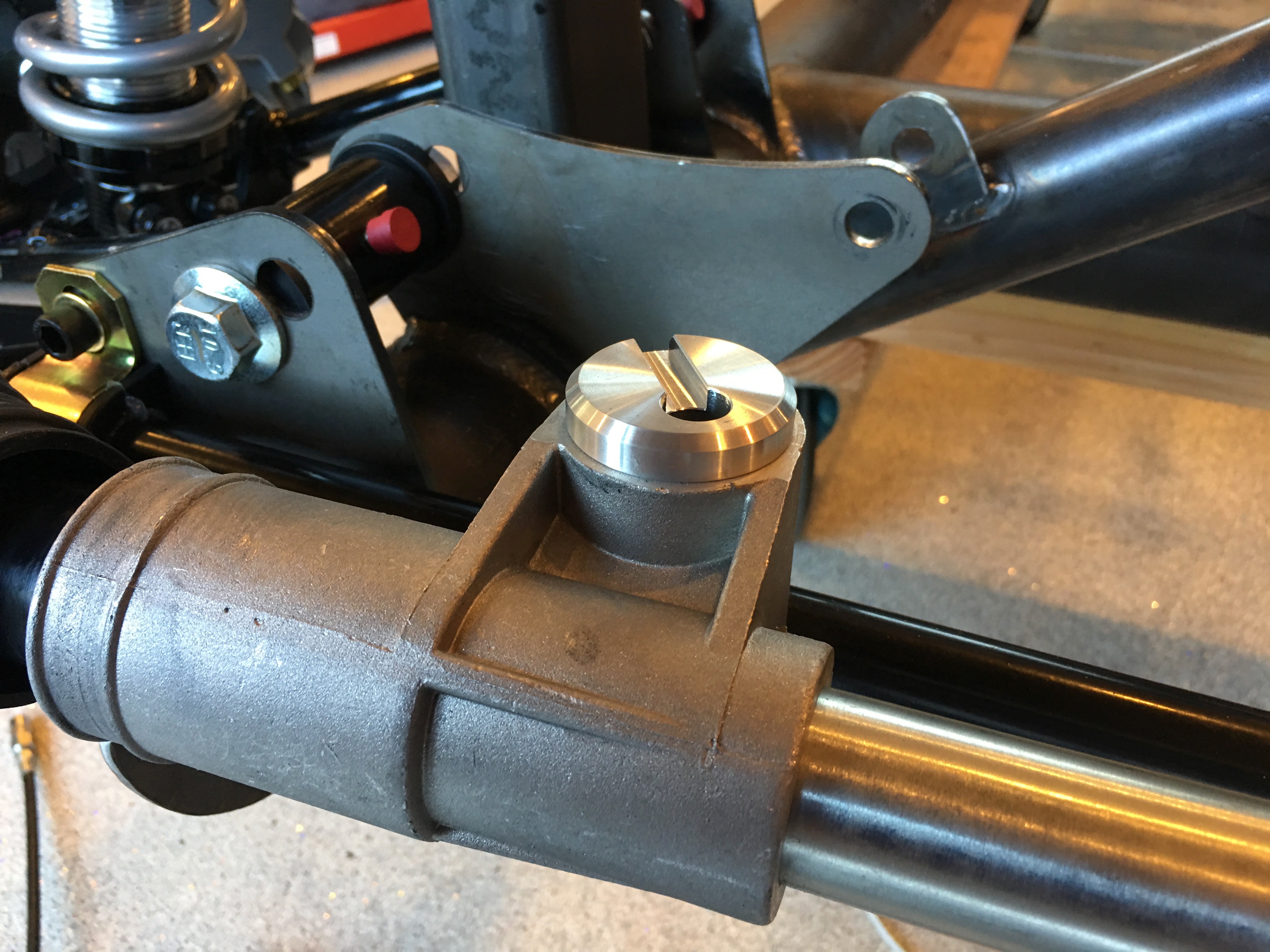
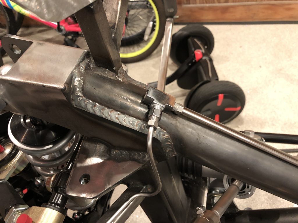
I started with a fairly short piece of brake line that connects the front left fitting to a tee that will sit on top of the x-frame tubing.

Then bent up a mirror image piece for the other side.

This one runs along the top of the x-frame to the same tee.

A final piece will run from a bulkhead fitting on the front of the driver’s foot box to the other side of this tee.

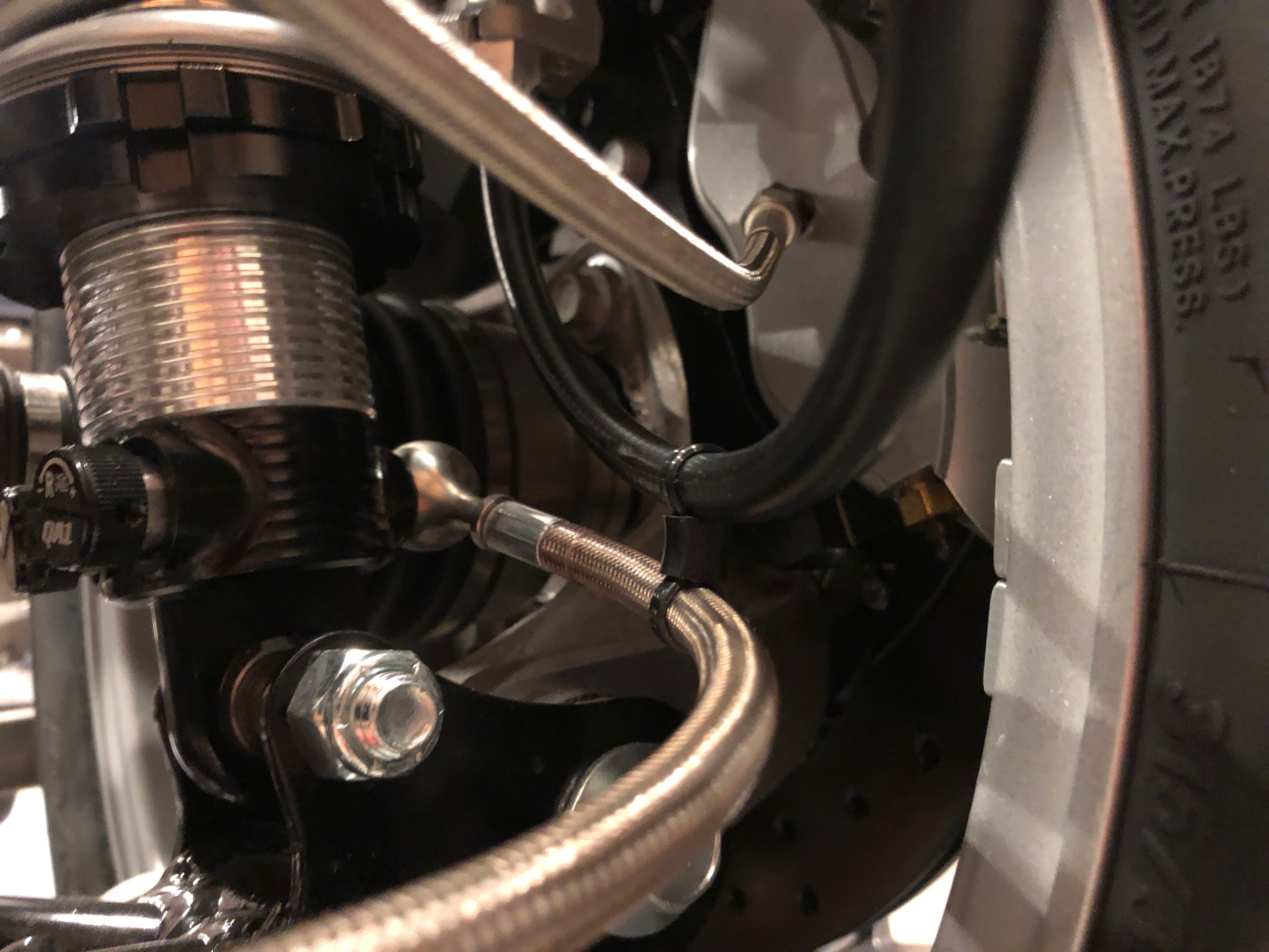
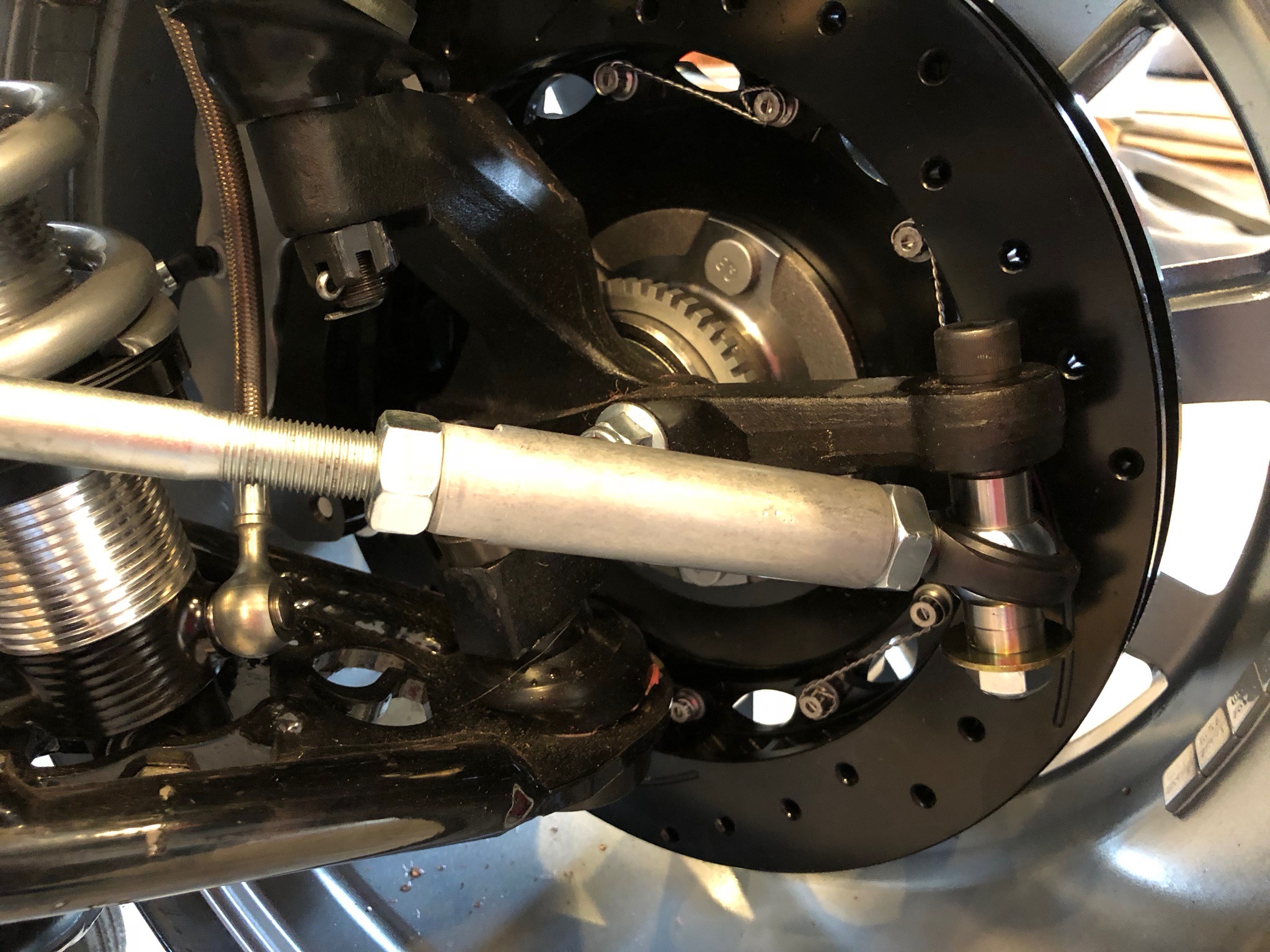
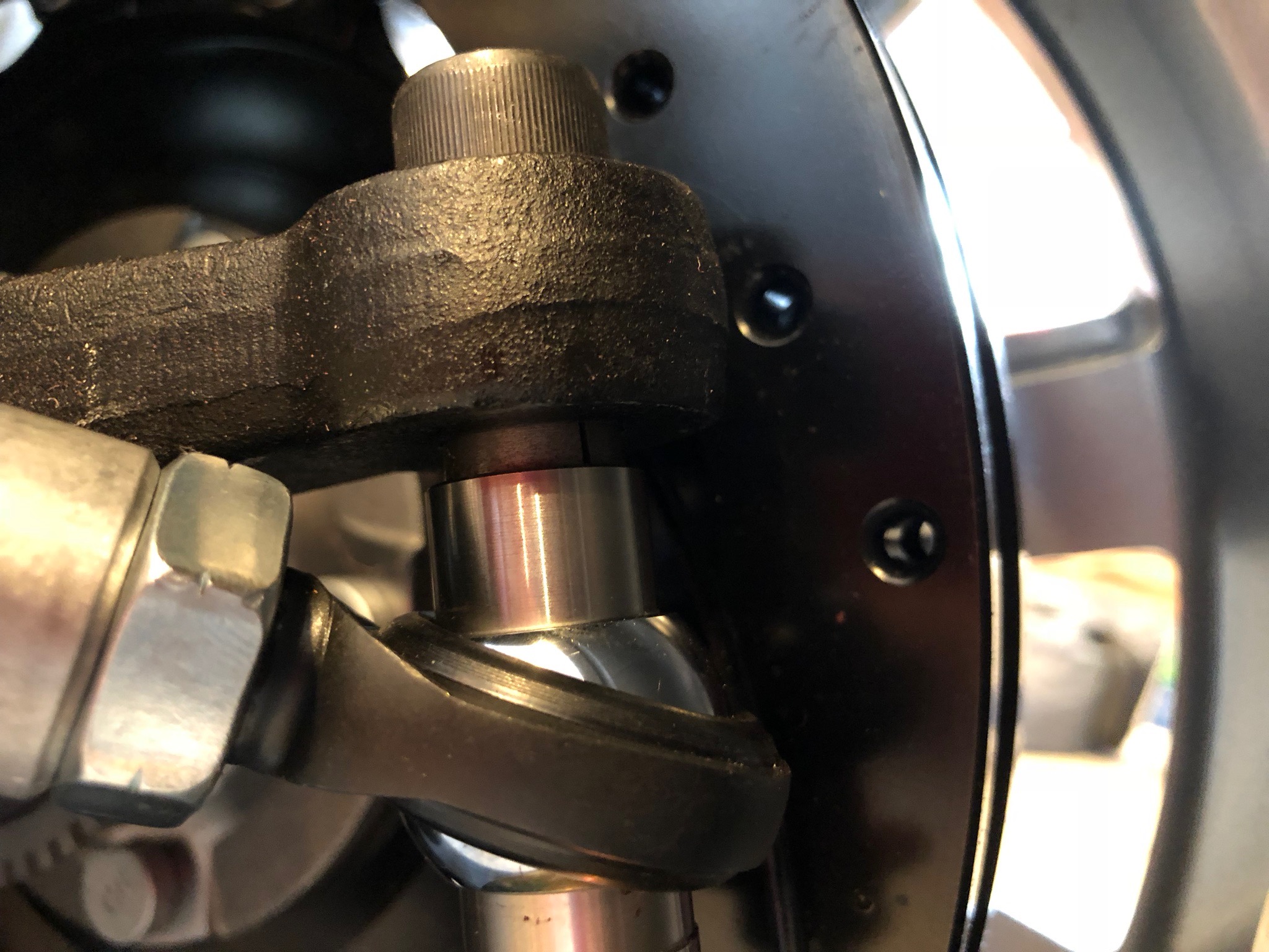
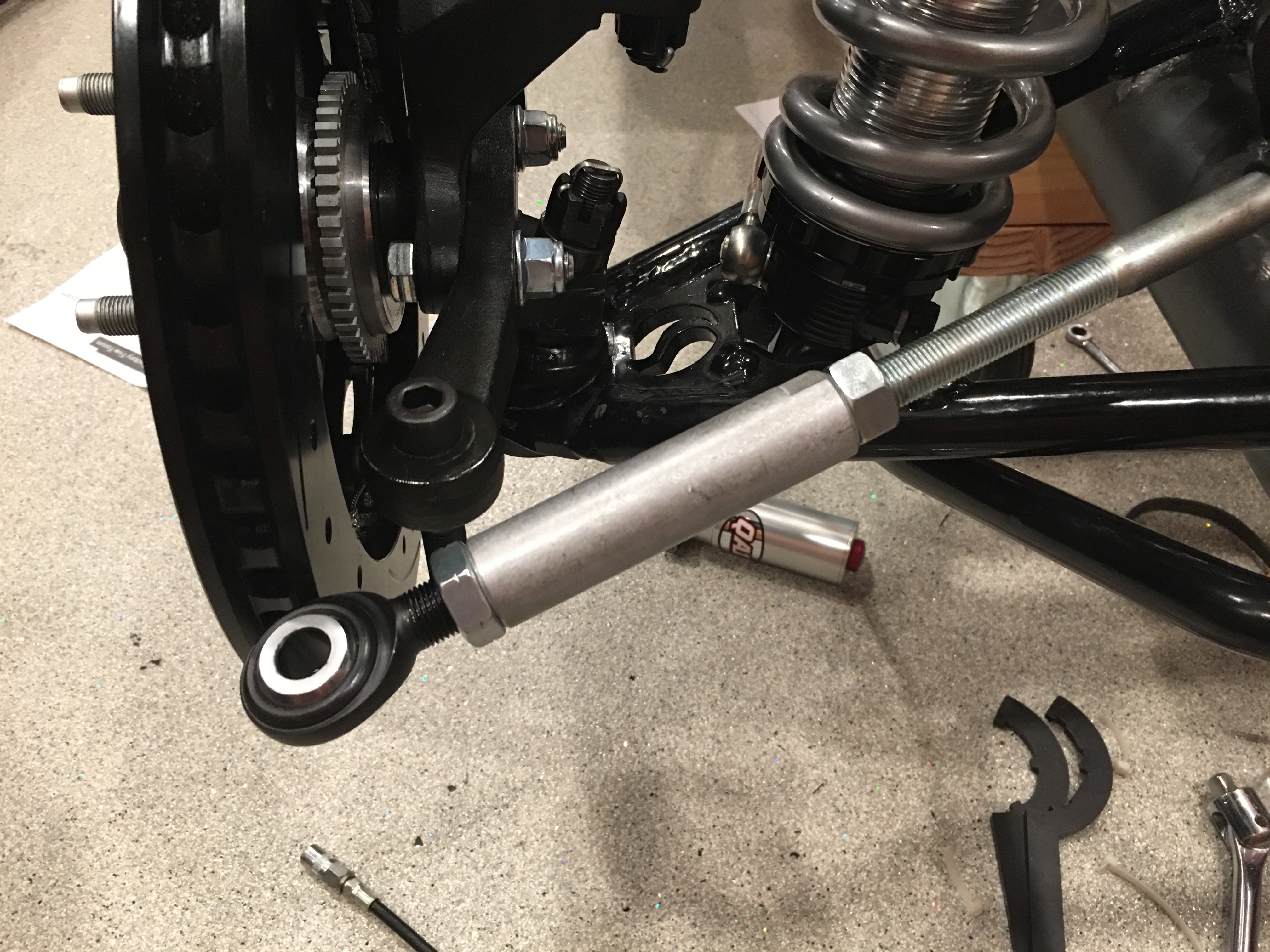
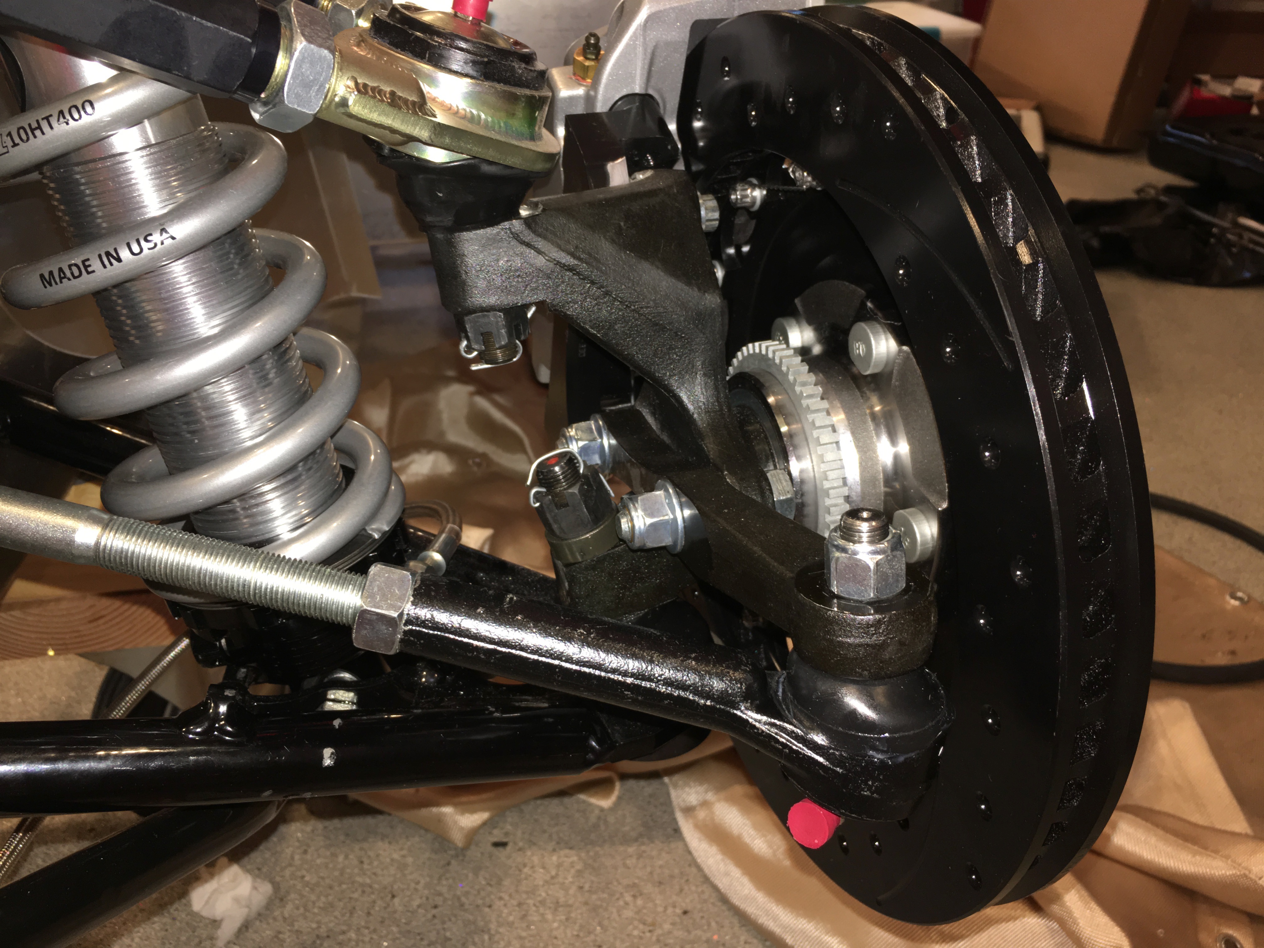
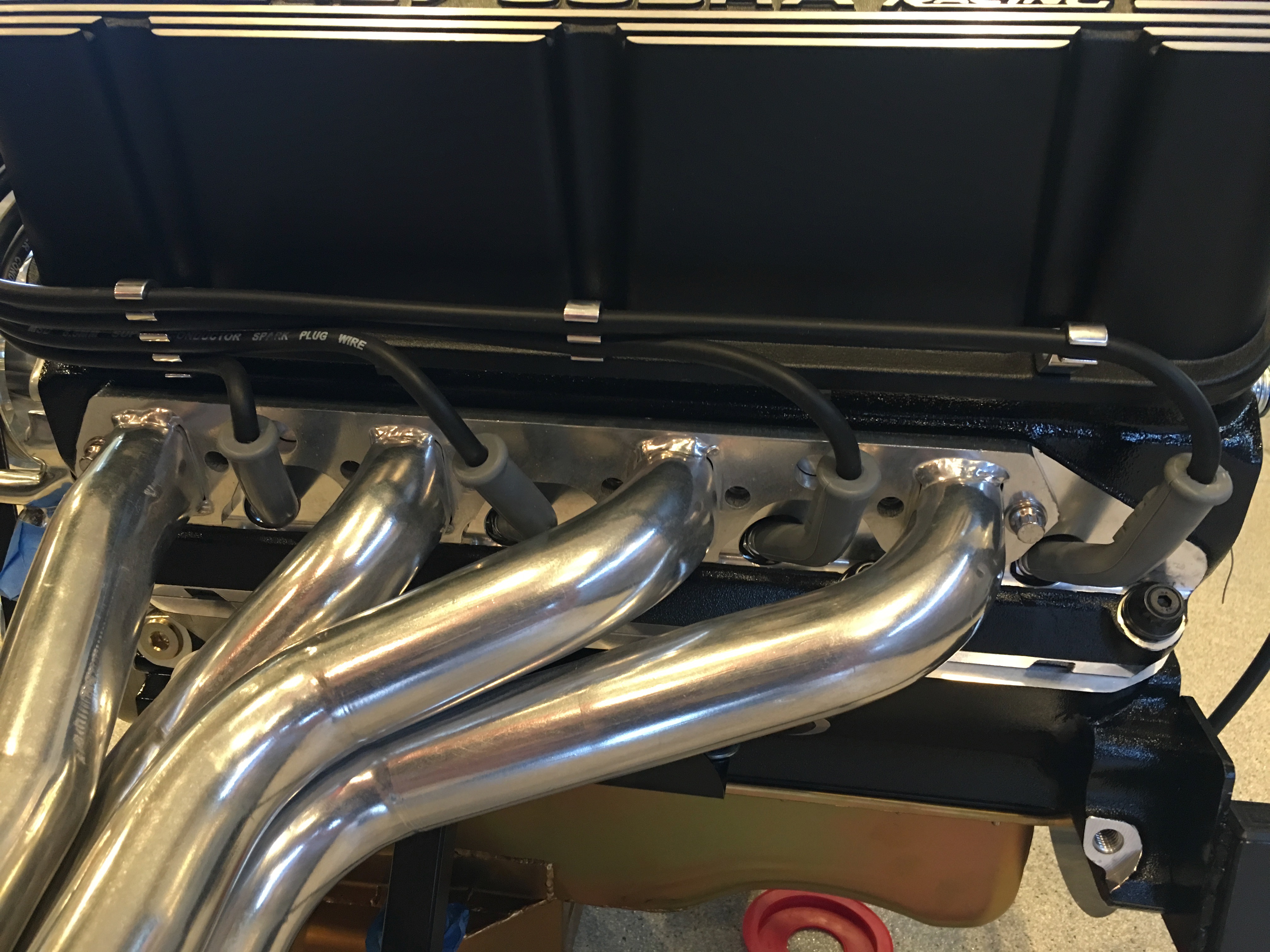
With the hard lines in place, I installed the fitting in the brake caliper and connected a piece of stainless brake hose.

I then did the same thing on the other side.

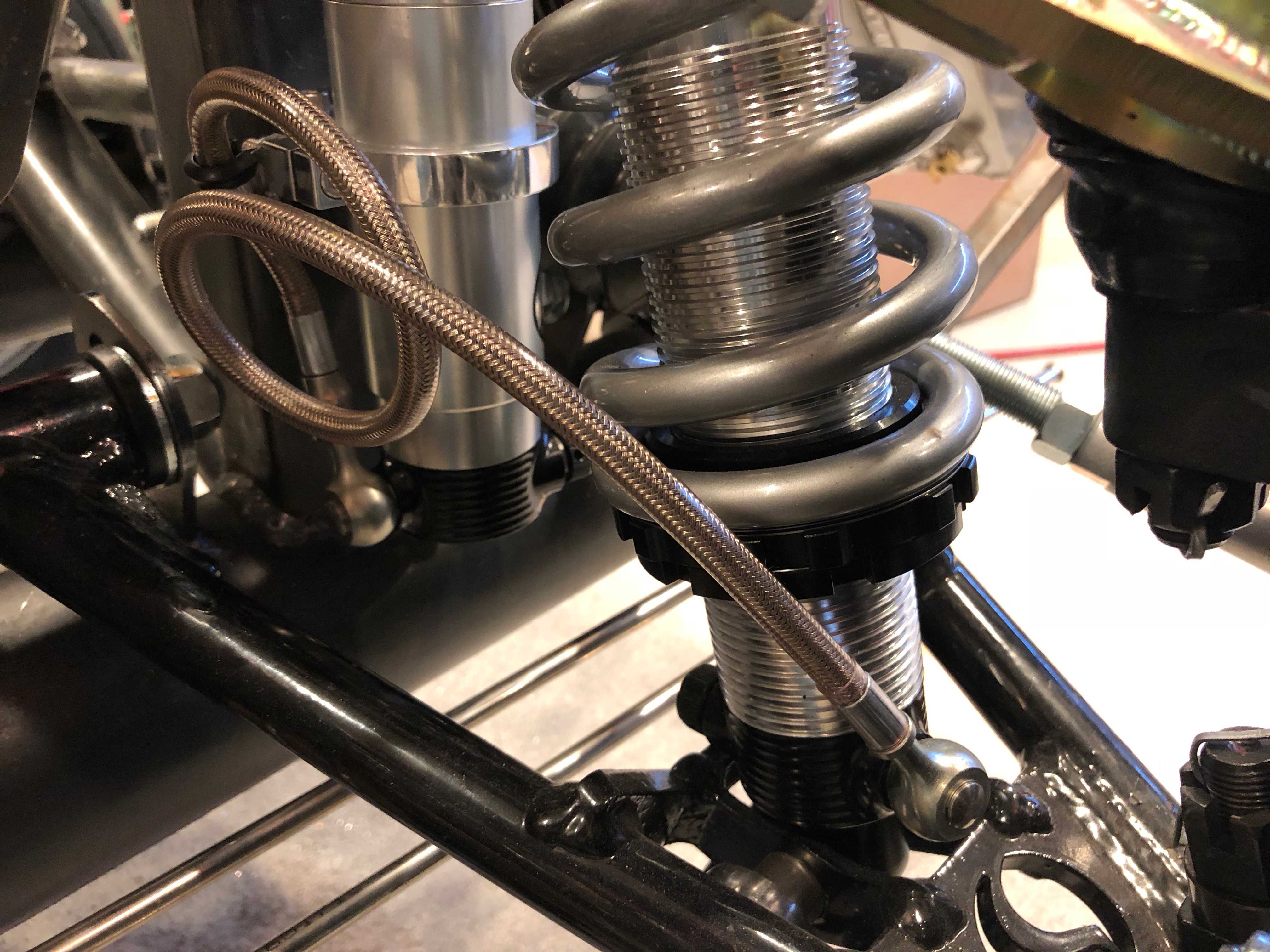
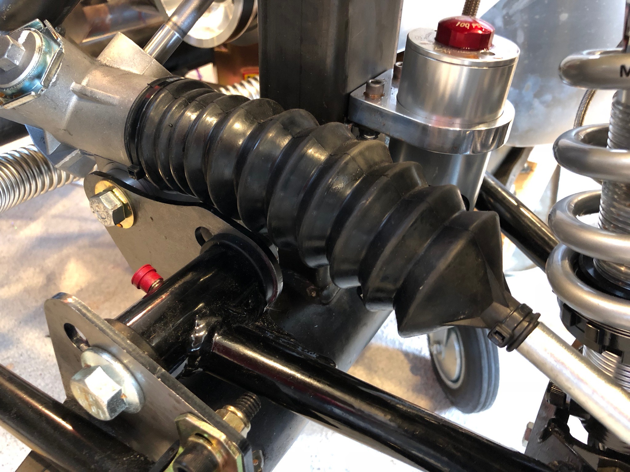
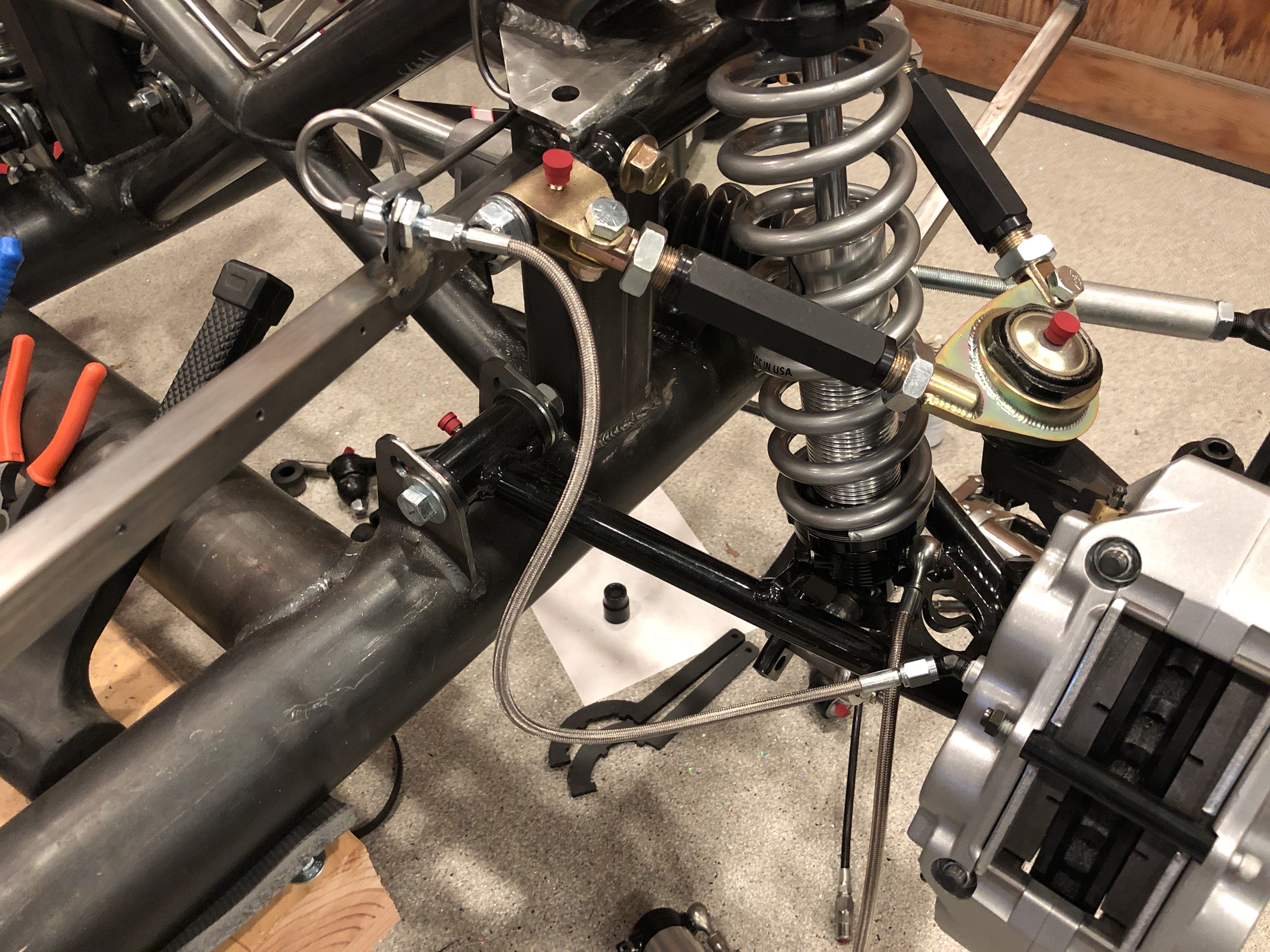
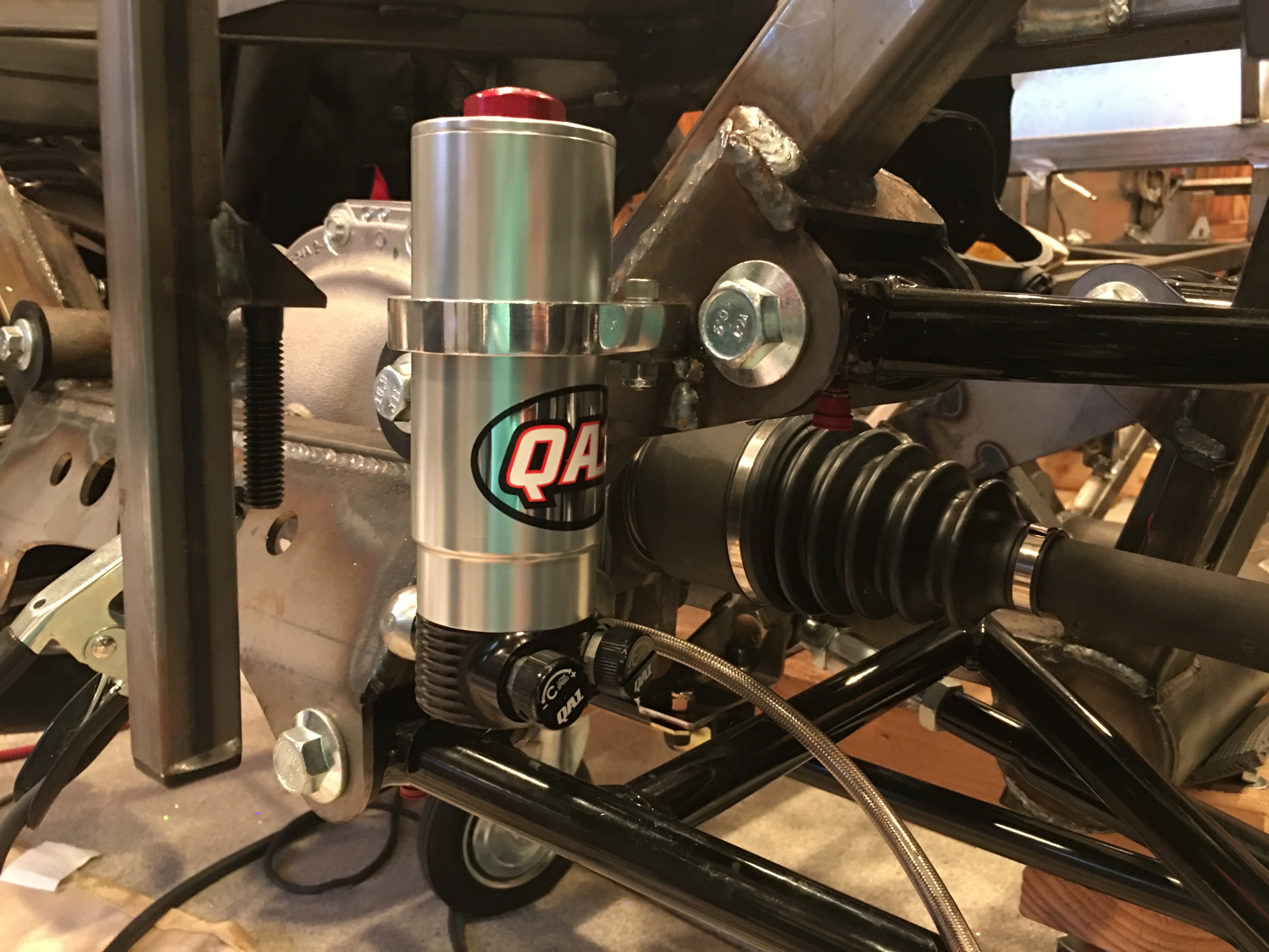
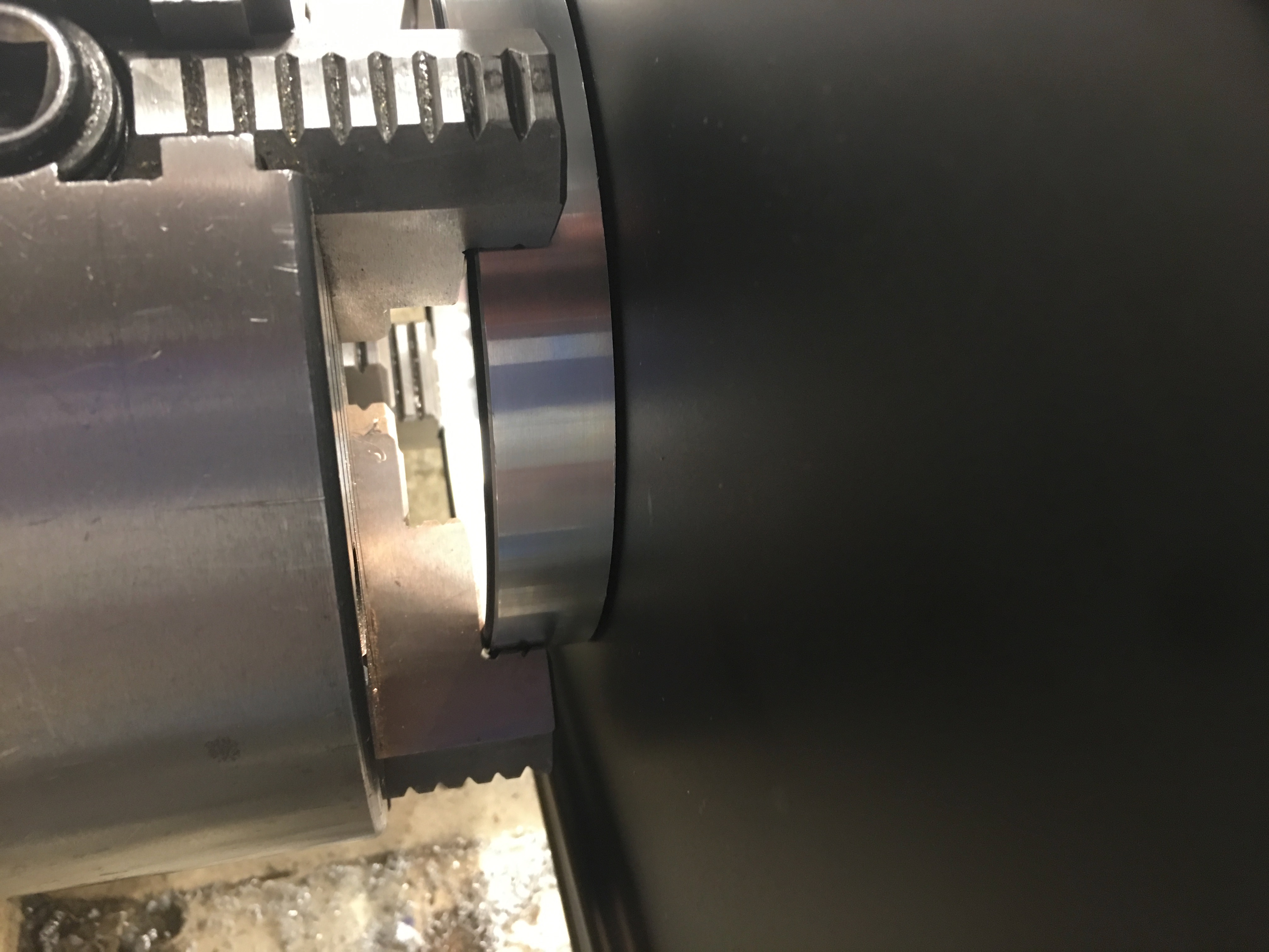
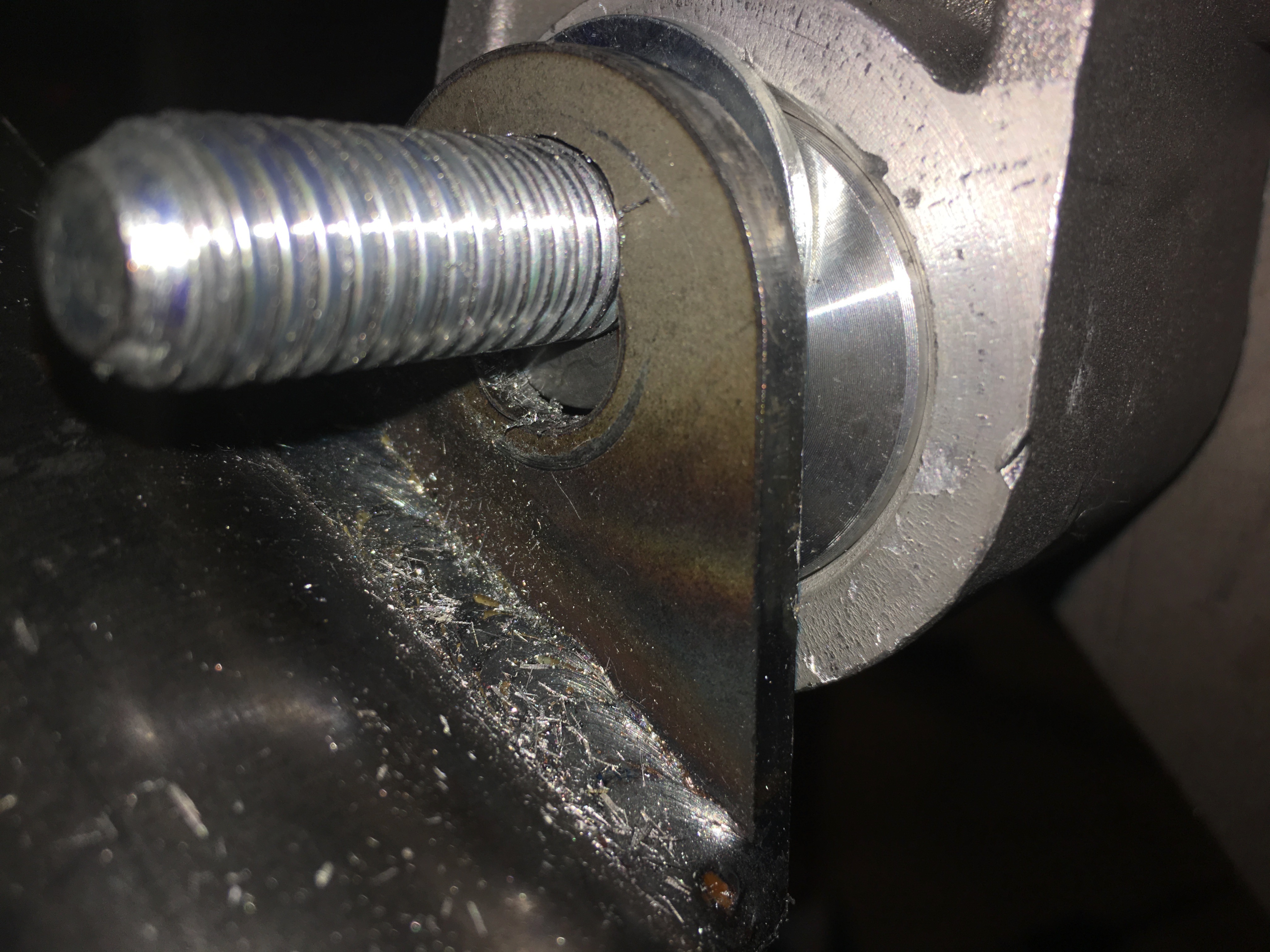
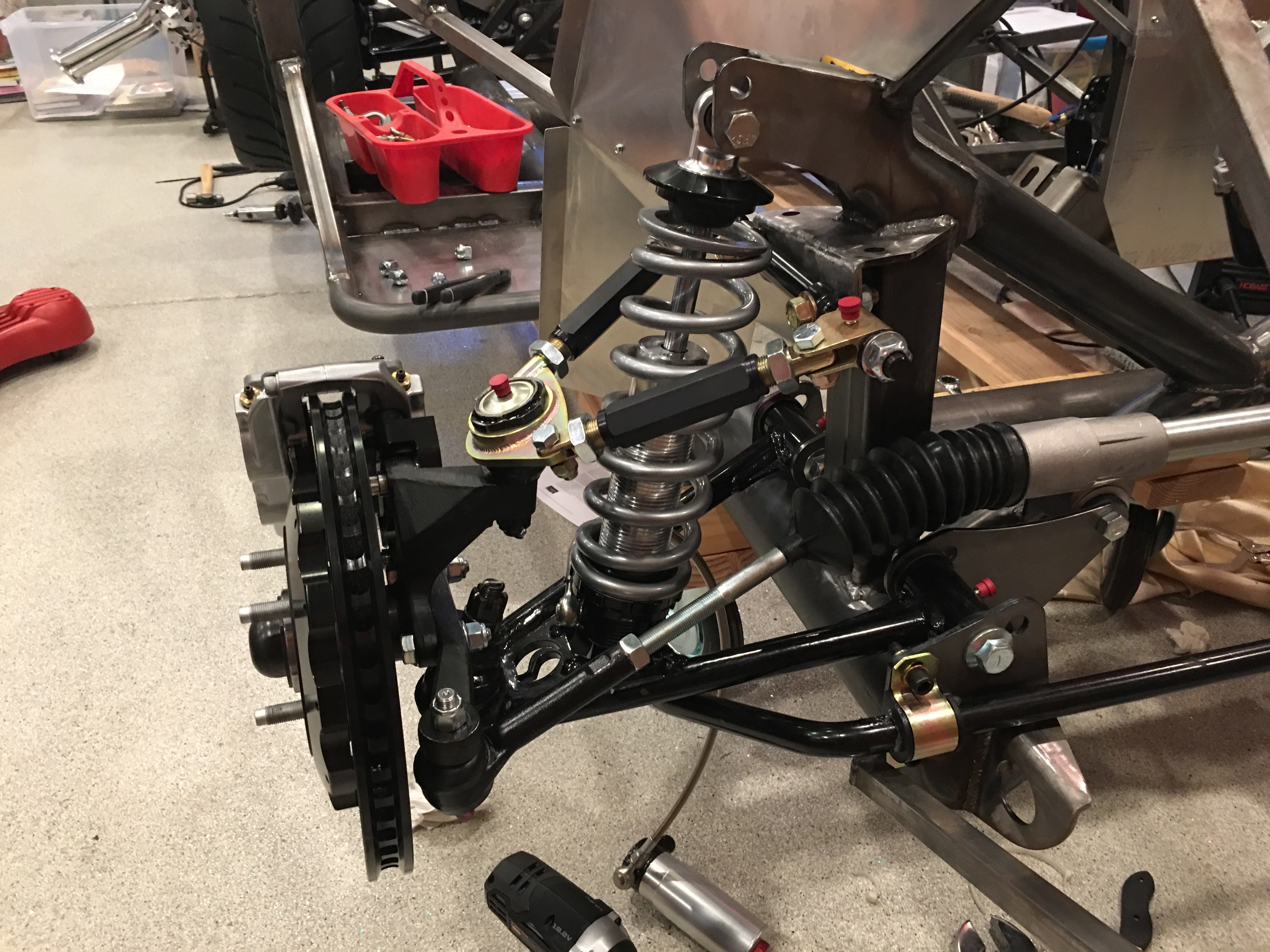
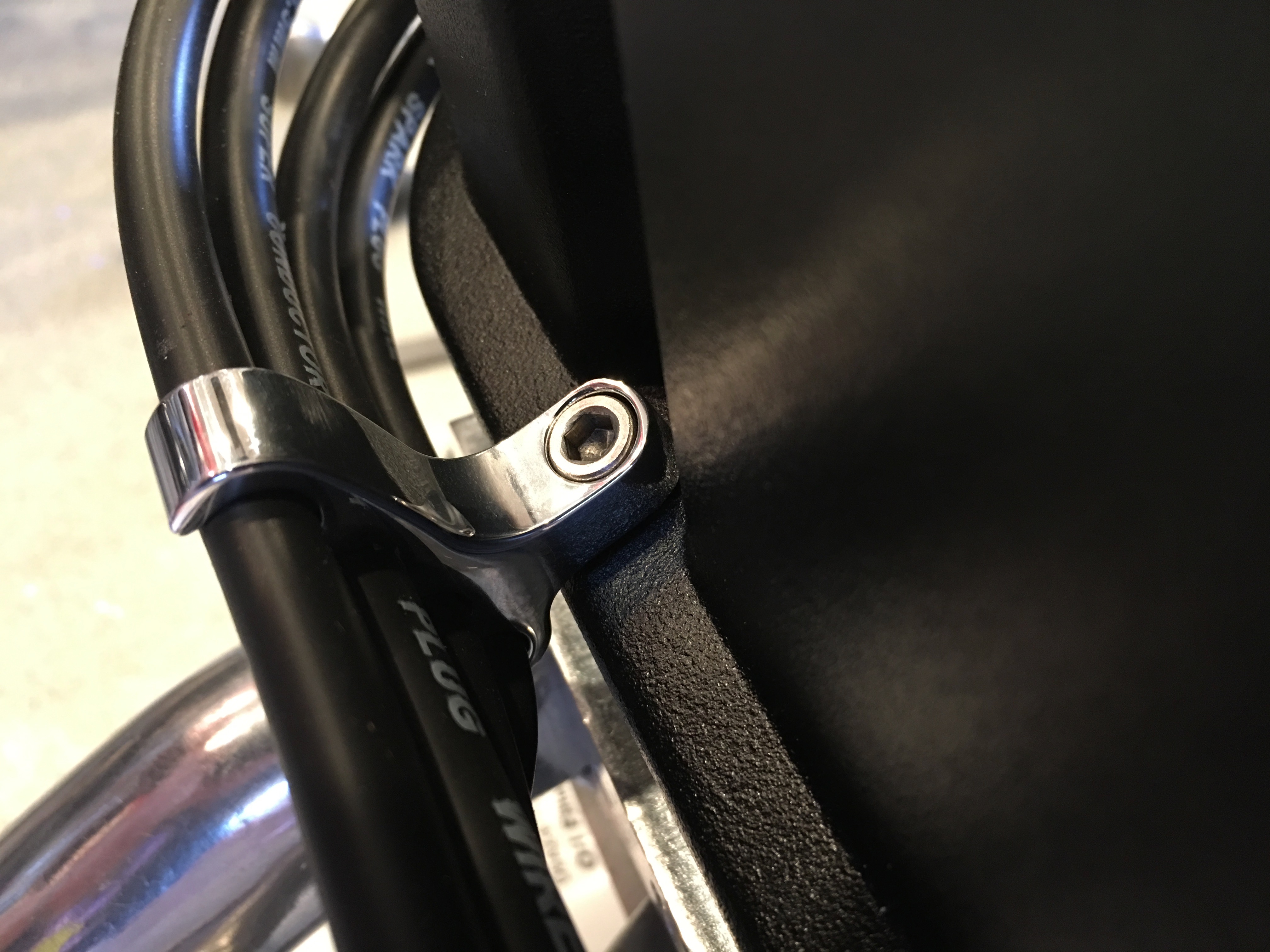
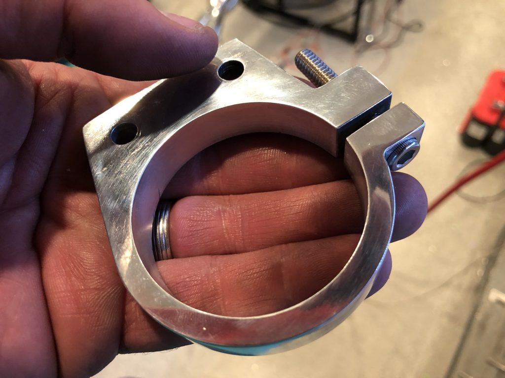
Finally, I decided to mount the front strut reservoirs. I decided to clamp the tubing to the screw that is used to secure the strut reservoir. To do that, I need to use a longer clamping screw, but the ones I had have a section without threads near the head. I used a 1/4″ reamer to remove a portion of the threads.

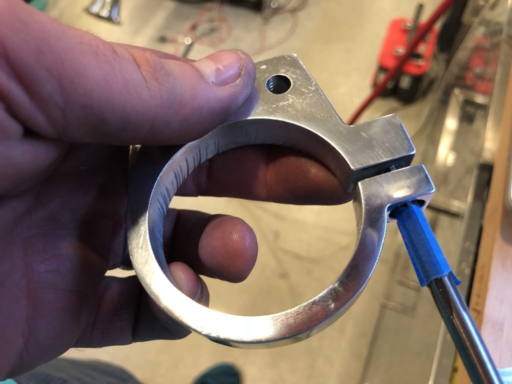
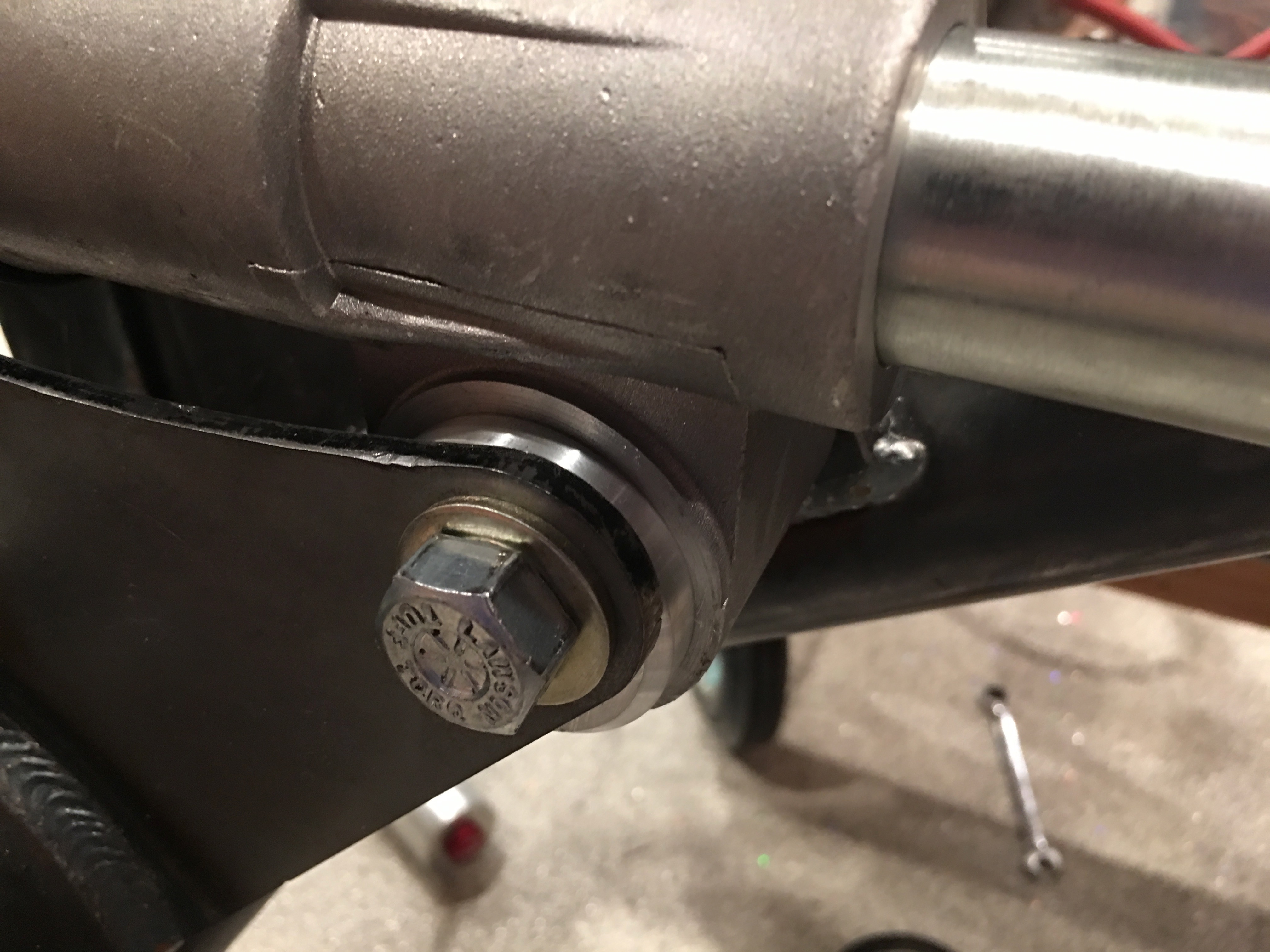
This lets me install the longer screw.

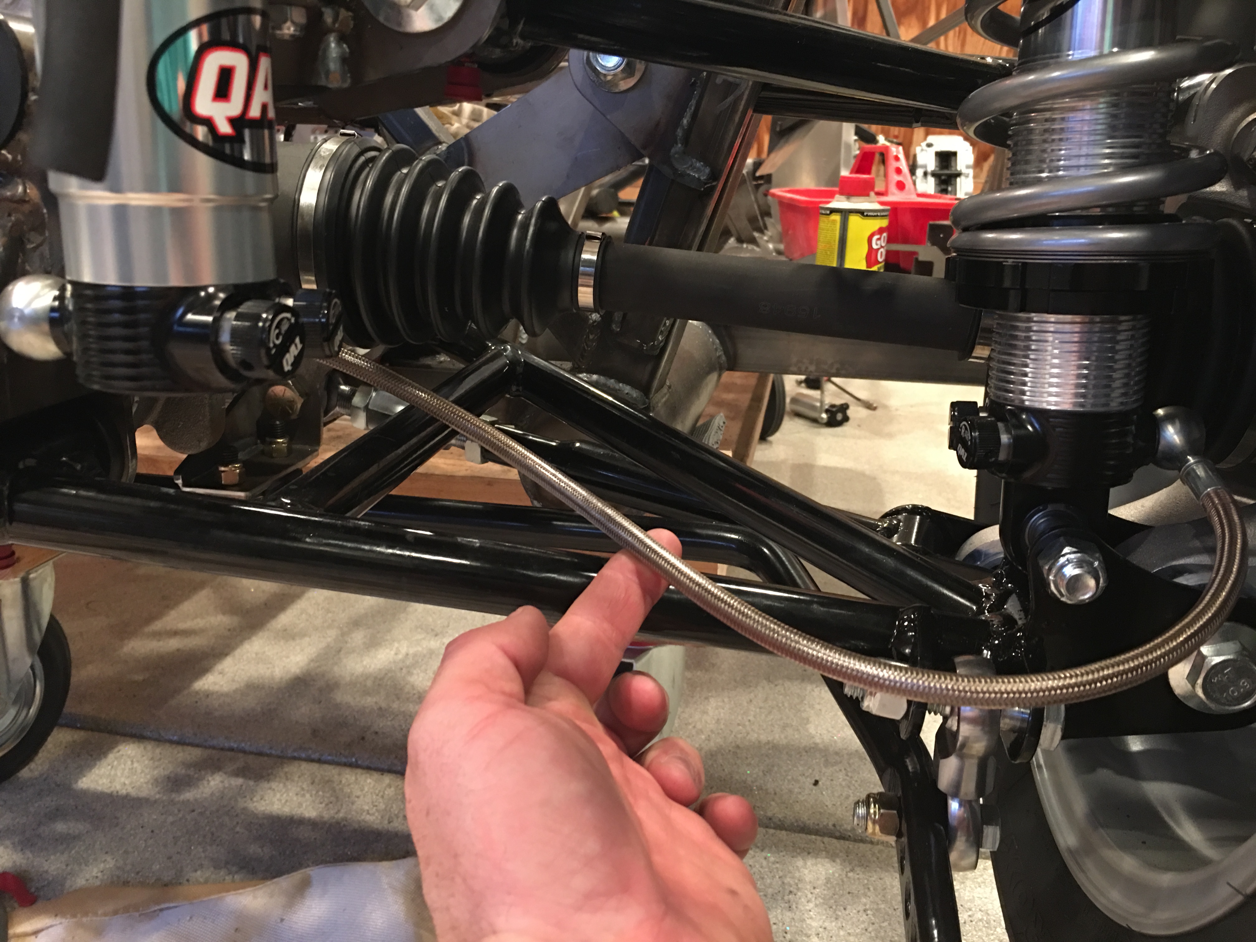
I then welded the steel brackets to the vertical pillars. Excuse the ugly welds, I’ll have to clean these up when the car is disassembled.

I slipped the strut reservoir in place and tightened down the clamping screw. I then used a cushion clamp to secure the hose to the back side of the clamp.

Prepping Engine for Dyno Shop

I’ve got a handful of details left to wrap up before we can run the engine at the dyno shop. First up, I needed to plumb the fuel filter between the fuel pump and the throttle body. I had a few scrap pieces of hose laying around from my airplane build, so I used one to insert the fuel filter into the supply line.

I also temporarily wired up the fuel pump to the FiTech unit. I’ll replace these terminals with better ones during the final wiring on the car, but this is what I had laying around that fit these large studs.

I also needed to wire up the ignition coil to the FiTech unit since it controls the ignition timing. Most of the car will be wired with automotive TXL insulated wire since that’s what comes in the Infinitybox wiring harness, but I don’t have any of that right now. I used some MIL-W-22759/16 wire I had laying around (which is better than the TXL wiring anyway). This cable snakes under the ignition coil (where it will be secured with a cushion clamp) and up behind the distributor where it follows the rest of the wires around the right side of the throttle body to the back of the engine.

The coil needs to be connected to two wires coming off one of the other FiTech connectors, so I looped them back. The white wire will also be connected to the switched side of the ignition switch.

Since I don’t want to mess with the key switch now, I just rigged up an old toggle switch to turn the ignition on and off.

I also temporarily attached the ground strap to the engine block. At the other end is the red wire that goes to the fuel pump ground. I didn’t have any 18+ ga black wire around, so I used red and flagged it with some black electrical tape. None of this will end up in the car.

While I had my tools out to install the WeatherPak connectors on the back of the engine, I connected the electric power steering motor to the controller.

Mounted Rear Strut Reservoirs

I welded on the mounting brackets for the rear strut reservoirs. I ended up deciding to mount them to the side of the upper rear control arm mounting bracket. This puts it well out of the way of any moving parts and provides nice routing for the hose that connects the strut to the reservoir.

The hose follows an ‘S’ curve from the strut to the reservoir. I’ll anchor it to the lower control arm near the middle with a couple of adel clamps so that it can’t rub on anything.

Fabricated Mounting Brackets For Strut Reservoir Brackets

The strut reservoir brackets that I fabricated a couple of weeks ago need to be bolted to the chassis. To allow this, I fabricated some steel mounting brackets that I’ll weld to the chassis. I started with some 1/8″ thick 1.5″x1.5″ steel angle and cut down both legs a bit and match drilled it to the reservoir brackets.

I then clamped the mounting brackets in an angle vise to bevel the ends to match the reservoir brackets.

I then flipped the brackets over to bevel the other end.

With a drill bit used to line up the holes, you can see how the mounting bracket matches the angle of the aluminum reservoir bracket.

After cleaning all of the burrs off with a scotchbrite wheel, I used the media blaster to clean them up so that they’re ready to weld to the chassis.

Air Cleaner Spacer and Steering

When I ordered the hold down kit, I decided to go ahead and pick up an aluminum spacer for the air cleaner. I really need a 3/4″ high spacer, but the only options were 1/2″ and 1″, so I picked up the 1″ and removed 1/4″ from the height on the lathe.

I then cut a new recess on the inside 1/2″ down from the top and opened it up a few thousanths wider than the air filter base flange.

I test fit the air filter base and it’s a nice, snug fit onto the spacer.

On the other side, you can see that the spacer doesn’t sit flush on the bottom of the air cleaner base. The problem is that the air cleaner base is a stamped steel part and there is a radius around the flange.

I machined a bevel on the inside corner of the spacer to allow space for the radius.

Now the spacer fits tight against the air cleaner base.

I installed the 1/4″-20 to 5/16″-18 adapter in the throttle body.

I had to cut down the shaft a bit so that it is the right length for the air cleaner plus spacer.

I did a final test fit of the air cleaner and everything looks great.

There’s now about 1/4″ of space above the throttle body which is plenty to prevent anything from touching and to clear the fittings that will thread onto the fuel connections you see here.

With the test fit complete, I used some black RTV to adhere the spacer to the air cleaner base. This seals out any leaks and means we don’t have to install the spacer separately. You can see here that the spacer also has an o-ring installed in the base so that we don’t need to use a gasket when installing the air cleaner.

Our steering rack wasn’t centered before, so you could turn the wheels farther one direction than the other. You can compensate for this by using different thickness steering spacers on each side, but the right fix is to center the rack in the car.

My order from Breeze Automotive arrived today with their offset rack mounting kit which let’s you shift the rack from left to right and also lower it a bit which helps reduce bump steer.

I installed the rack and some spacers and then adjusted the offset bushings until the rack was exactly centered in the chassis. One additional advantage of using the Breeze kit is that the steering rack is rigidly mounted which means it acts as a structural member of the chassis and increases its stiffness.

The rear hole on the passenger side needed to be elongated vertically since it wasn’t quite aligned with the front hole. It wasn’t really a problem with the polyurethane bushings since they could flex a little, but the rigid bushings require the holes to be aligned.

I also picked up a bump steer kit from Mike Forte. I threaded it in all the way on both sides and then loosened it until I had some adjustment available. With the steering rack centered and the wheel roughly aligned, it looks like the tie rod is nearly 2″ too long. I’ll confirm with Mike Forte before cutting them though.

Brake Fitting and Strut Reservoir Brackets

The Factory Five kit has rigid brake lines between the master cylinders and each of the wheel wells. At the wheel well, there is a fitting that transitions between the rigid line and a flexible stainless line that runs out to the caliper. This fitting is held in place with a small bracket. The kit only came with two of the brackets (probably because I deleted the brakes from the kit) and they’re stainless. Since I plan on welding the brackets on, I decided to fabricate four new brackets out of mild steel.

I drew up a simple bracket in Autodesk Mechanical and cut them out on the waterjet. It took a couple of tries with different tab size settings and cut speeds until we got four that we were happy with.

I used the disk grinder to sand off the tab and clean up the edges.

I then sandblasted all the rust off.

The parts from FFR have a couple of holes and are riveted to the side of the 3/4″ chassis tubing. Instead of riveting ours on, I put a bend in the brackets so that I can weld them to the top of the 3/4″ tubing.

Here’s one of the bent pieces along with the other three that are ready for bending.

After finishing up the brake fitting brackets, I loaded up the cut path for the bracket I designed to hold the remote strut reservoirs. I’m cutting these out of a piece of 1/2″ 6061 aluminum.

I’m glad I did the brake fitting brackets first since I had plenty of extra steel and could afford to make a couple of mistakes (as I did). For the reservoir brackets, I only had a big enough piece of aluminum to cut the four I need. Fortunately, everything worked perfectly and every piece turned out great.

I designed these with a tab on the left that I can use to clamp the bracket tight around the reservoirs. I also cut a couple of 1/4″ holes in these so that they can bolt to a piece of angle steel that I will weld to the chassis.

I needed to use several tools to drill the holes in the tabs, so I set up a couple of positioning fixtures to assure every piece is clamped in precisely the same location. The part sits on the fixture on the right to align it with the bed; this assures the hole is exactly perpendicular to the tabs. The fixture on the left provides a hard stop to precisely position the part in the X axis (along the bed). The Y location is fixed by the back of the vise which doesn’t move. The vise clamps both the upper and lower portions of the tabs so that there is no movement in the tabs during machining.

I used a center drill to create a small pilot hole in the center of the tab. I then drilled through both parts of the tab with a #7 bit and then through the upper part of the tab with a 1/4″ bit.

Afterward, I use a 3/8″ end mill to create a recess 0.235″ deep.

After threading the lower part of the tab with a 1/4-20 tap, I test fit a 1″ socket head bolt. The socket head bolt fits perfectly in the recess and is flush with the top of the tab. The 1″ bolt is a little long, so I’ll probably use a 3/4″ stainless bolt for the final install.

I sanded the edges smooth and used a drum sander to smooth out the inside of the hole until it’s a slip fit over the reservoir. Afterward, I polished the brackets until they are nearly a mirror finish.

The brackets hold the reservoirs perfectly. They slide over the reservoirs with almost no play and clamp tight with only about 1/2 turn on the bolt.

Fuel Tank and Steering Rack

We’re planning on running a FiTech EFI on our engine. The best way to set up an EFI system is an in-tank fuel pump since you really don’t want high-pressure pumps to pull fuel and it’s much easier for an external pump to lose its prime and cause the engine to die. I had planned on using FiTech’s new HyFuel in-tank retrofit pump, but the OEM tank from FFR is not ideal for this pump. The pump needs to mount on a fairly flat spot on the tank, but you really want the pickup to sit in the baffled part of the tank. Unfortunately, the baffle is pretty small in this tank and there is no flat spot above the baffle that will work without extensive modification to the tank.

After a bit of research, I’ve decided to ditch the OEM tank and I’ve ordered a Boyd Welding aluminum tank with built-in Aeromotive 340 Stealth pump. This pump will work fine with the FiTech EFI unit and is already installed for less than it would cost to buy the pump separately.

I got back to wrapping up the steering linkage. Unfortunately, I realized that I installed the steering arms upside down way back when I assembled the front spindles. Even more unfortunately, they can’t be removed without completely removing the spindle from the control arms. I purchased a ball joint separator and removed the spindles. Since I had them apart, I went ahead and swapped the ball joint boots with the ones I purchased from Energy Suspension.

Here’s the lower boot (highly deformed since the suspension is unloaded).

Here’s the upper boot (also fairly deformed). These are made from polyurethane and are quite a bit tougher than the ones that came off the ball joints. I’m glad I replaced these since both upper boots had already torn from the pressure on them when the suspension is unloaded.

I adjusted the length of the tie rods until the wheels are roughly aligned. This is probably as close as I can get this until the car is sitting on its tires at roughly the driving weight.

Spark Plug Wires and Steering Linkage

I temporarily fit the headers so that I could route the spark plug wires. I’m using the MSD multi-angle boot spark plug wires so that I can adjust the boots for the best clearance. I’ll do the final tweaking of the boot angles and wire position once the distributor is installed and all of the wires are cut to length.

I’m using some billet aluminum wire supports from Billet Specialties.

They replace the valve cover bolts and are a solid piece (unlike many of the cheaper wire supports). They’re sold in packs of two with between 1-4 spots for wires. I needed the following:

  • 3x 4 position
  • 1x 3 position
  • 2x 2 position
  • 1x 1 position

I also further trimmed the ignition coil bracket I made and polished it up before mounting it to the water pump. I needed to order some custom length bolts to mount this since the old bolts were too short.

There’s plenty of clearance between the bolts that attach the coil and the top of the water pump. The right most bolt looks like it’s not engaged sufficiently, but the stud is flush with the bottom of the nut. Given the low load on these, that is sufficient.

I pulled off the F panel on the left side and welded the brackets on securely. I think the steering linkage is installed for the last time before we drive the car.