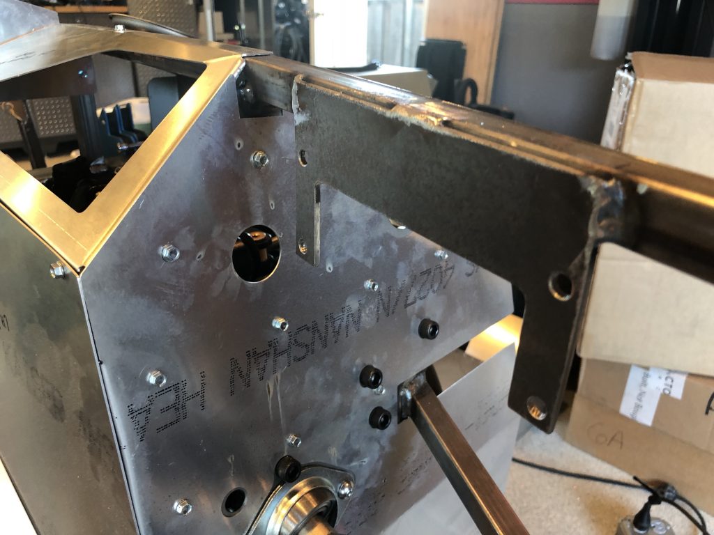
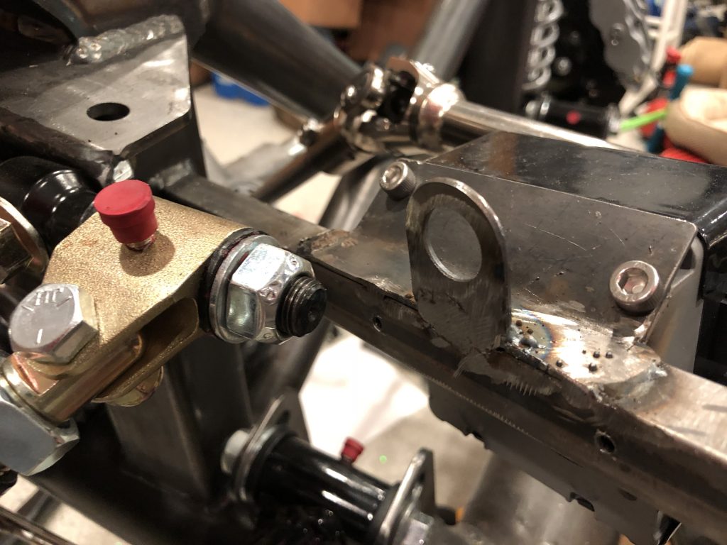
I installed the top and inside of the driver side foot box because I was considering installing the brake/clutch reservoir in the top of the foot box to ensure the bottom of the reservoirs were level with or higher than the inlet of the master cylinders. After some careful measurements, I determined I could install them in front of the foot box and meet this criteria. I quickly fabricated a bracket out of some 1/8″ steel plate I had and welded it to the chassis tube.
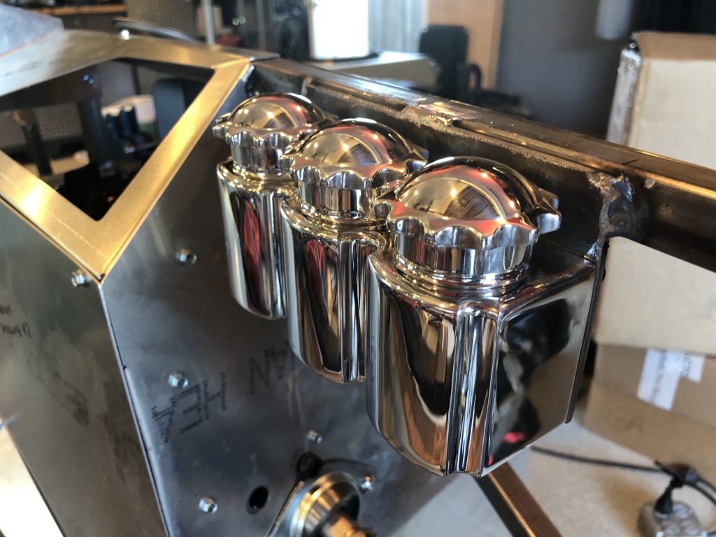
The triple reservoir bolts to this bracket through the holes visible above. The tops of the caps are even with the top of the chassis tube. I went with a triple reservoir so that there are separate reservoirs for the front and back brakes for redundancy. The left two reservoirs are for the brakes; the right is for the clutch.
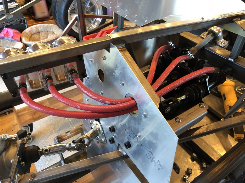
I connected the reservoirs to the master cylinders with some EPDM tubing. I didn’t have enough hose clamps to finish this, but I have more on order.
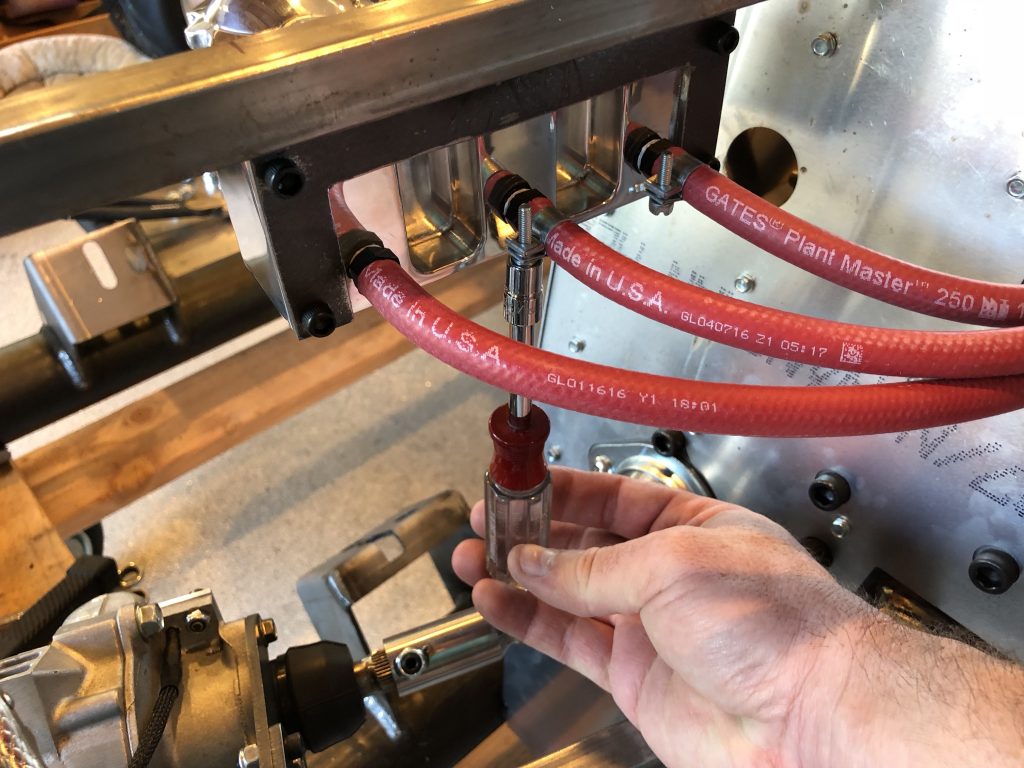
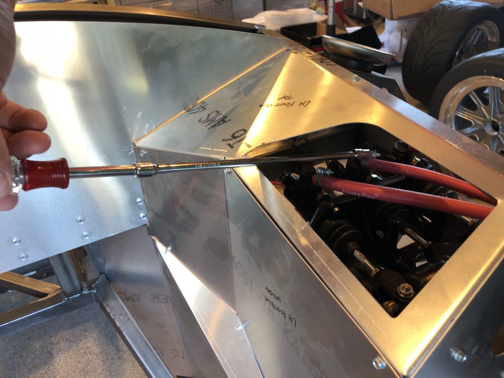
I’ve been trying to make sure that everything is accessible for future maintenance. Although access is easy now, with the body on, the only way to access these screws is from below.
I did the same thing with the hose clamps in the foot box. With the body on and the foot box riveted in place, the only access with either be from below or through this hole. I made sure I could access all of the hose clamps from above before tightening everything down.
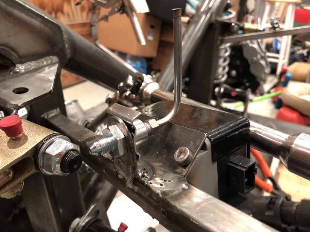
With the reservoir and master cylinder plumbing complete, I continued fabricating the hard lines. I welded on the front tabs near the aft end of the holes in the F panels. I’ll finish cleaning up the welds before the chassis is finished.
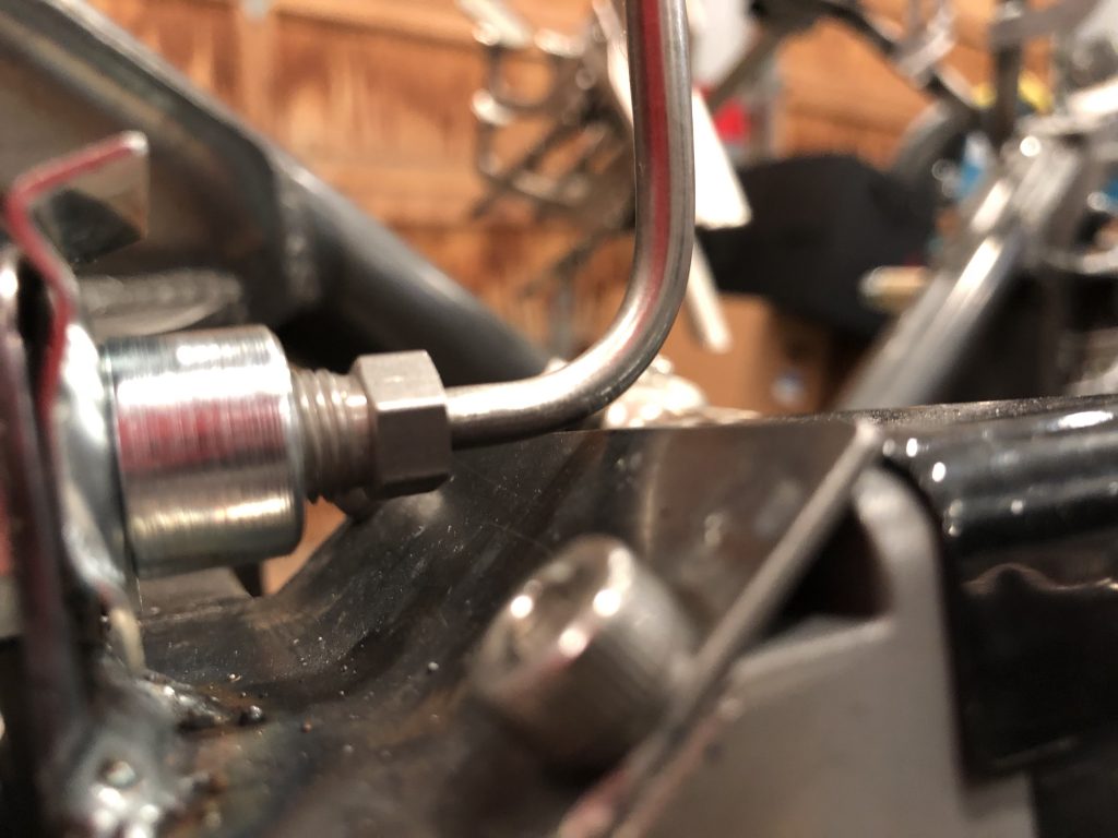
With the tab welded in place, I wanted to make sure that the brake line didn’t contact theelectric power steering support.
Fortunately, I got lucky and there’s about 1/8″ of clearance here.
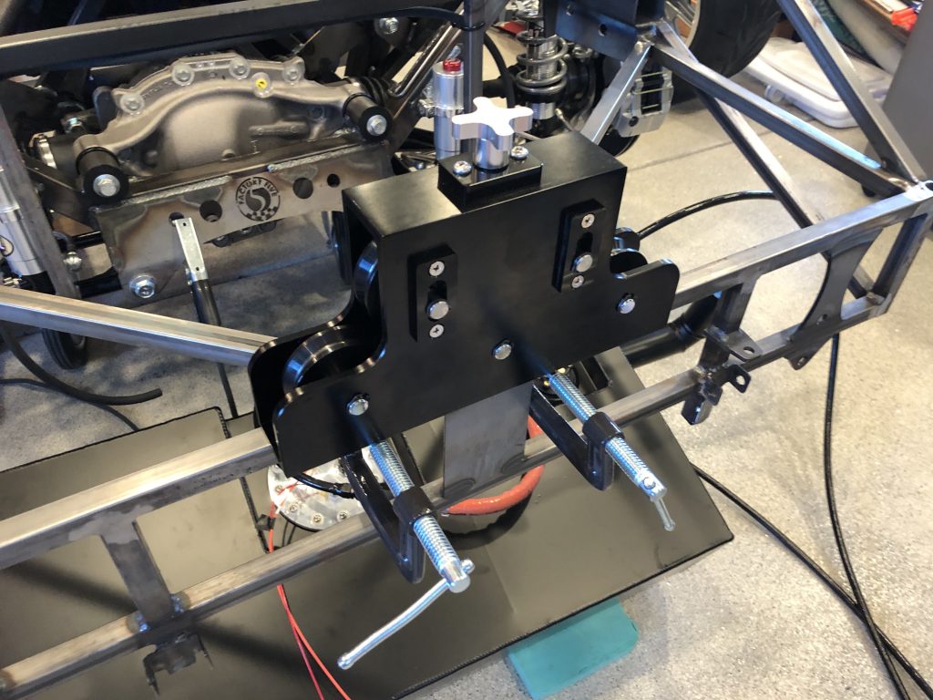
I clamped the tubing straightener to the aft end of the chassis so that I could straighten out some pieces of stainless brake tubing.
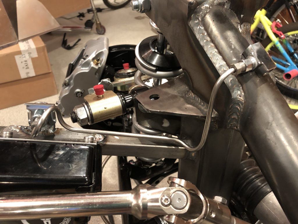
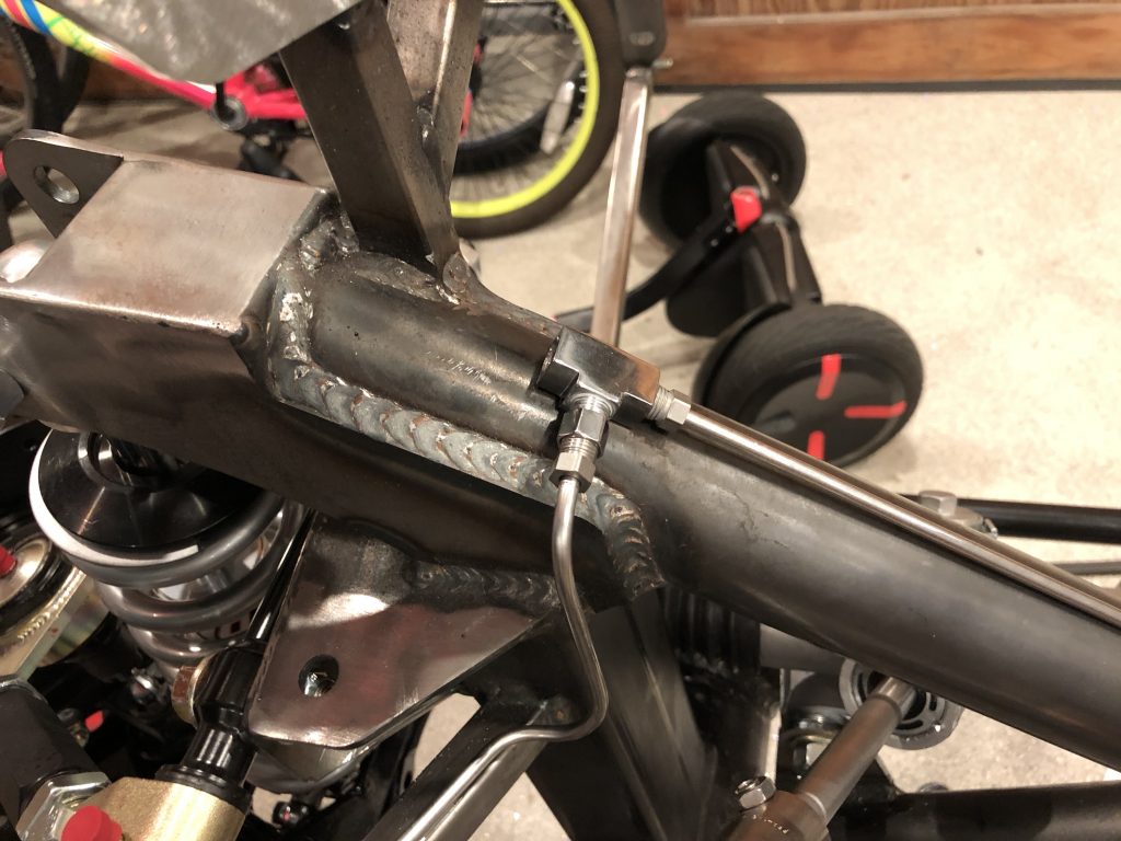
I started with a fairly short piece of brake line that connects the front left fitting to a tee that will sit on top of the x-frame tubing.
Then bent up a mirror image piece for the other side.
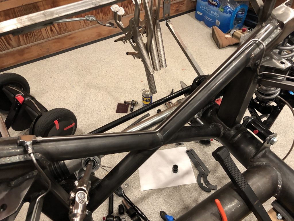
This one runs along the top of the x-frame to the same tee.
A final piece will run from a bulkhead fitting on the front of the driver’s foot box to the other side of this tee.
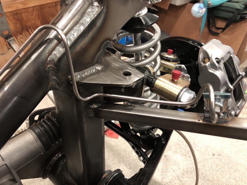
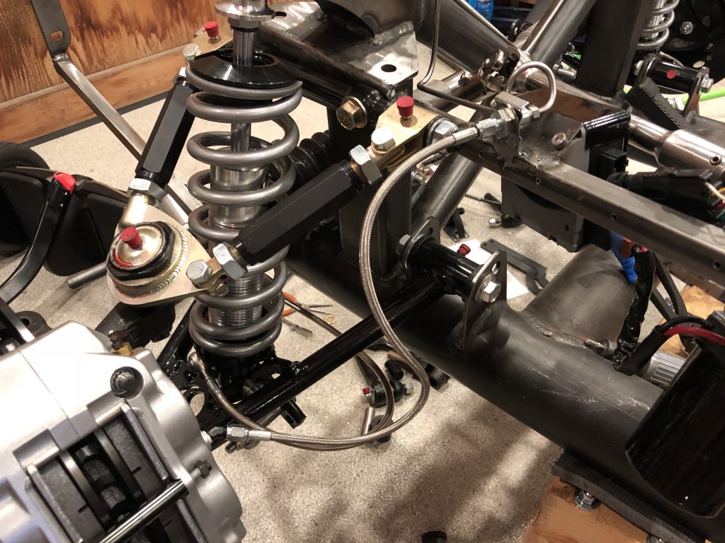
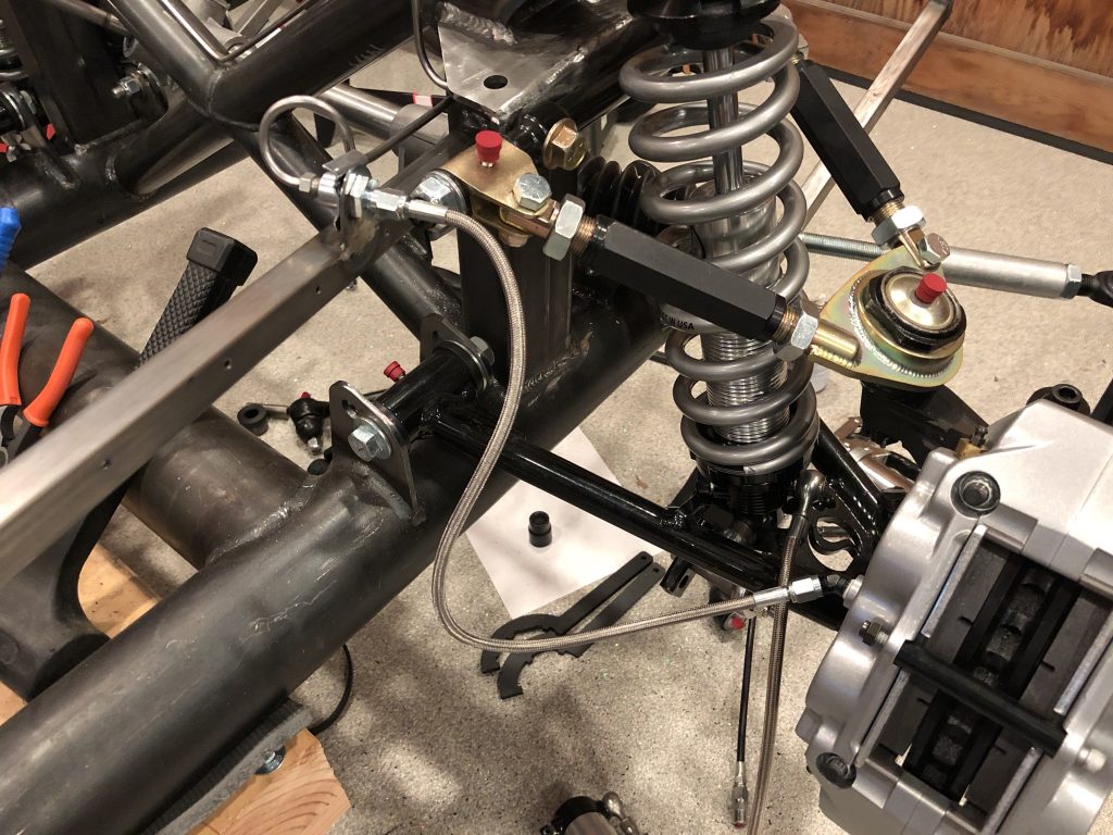
With the hard lines in place, I installed the fitting in the brake caliper and connected a piece of stainless brake hose.
I then did the same thing on the other side.
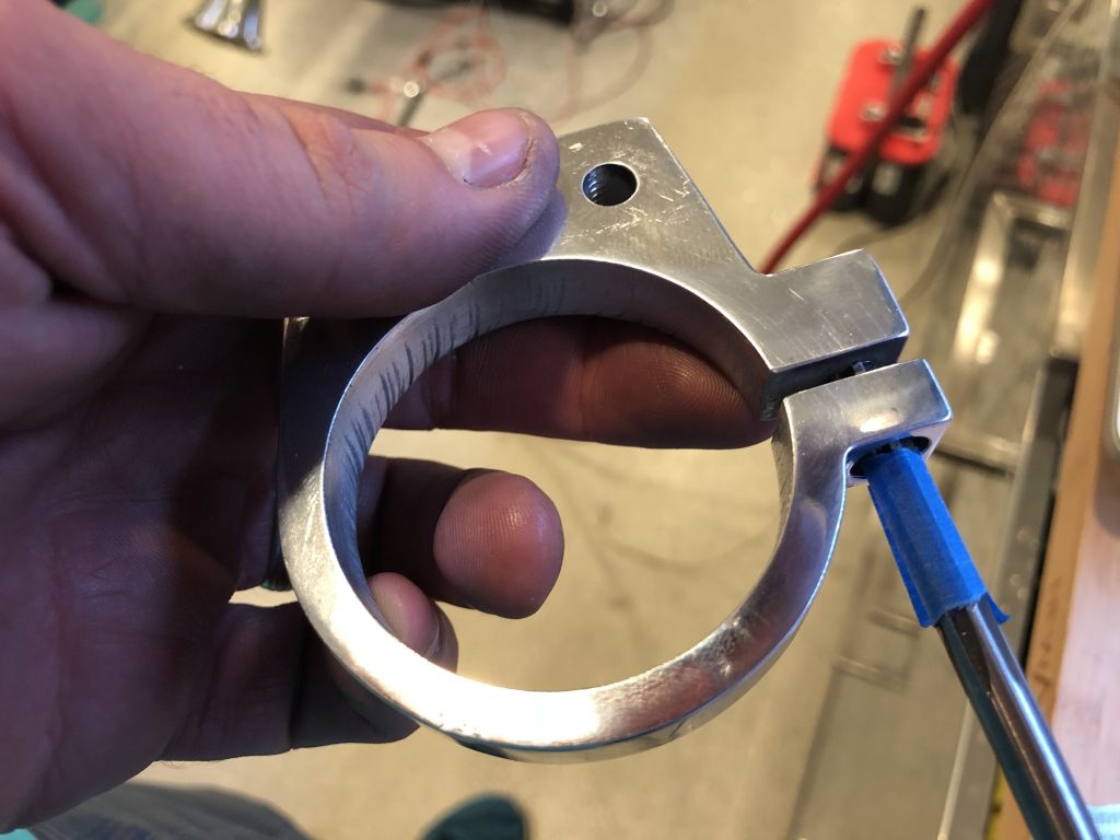
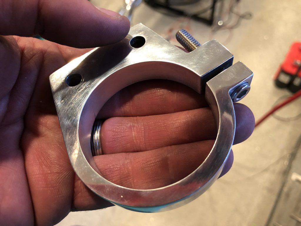
Finally, I decided to mount the front strut reservoirs. I decided to clamp the tubing to the screw that is used to secure the strut reservoir. To do that, I need to use a longer clamping screw, but the ones I had have a section without threads near the head. I used a 1/4″ reamer to remove a portion of the threads.
This lets me install the longer screw.
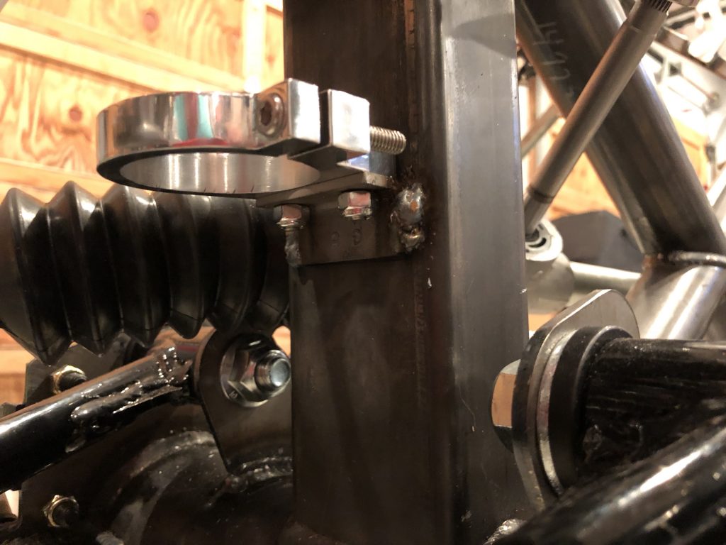
I then welded the steel brackets to the vertical pillars. Excuse the ugly welds, I’ll have to clean these up when the car is disassembled.
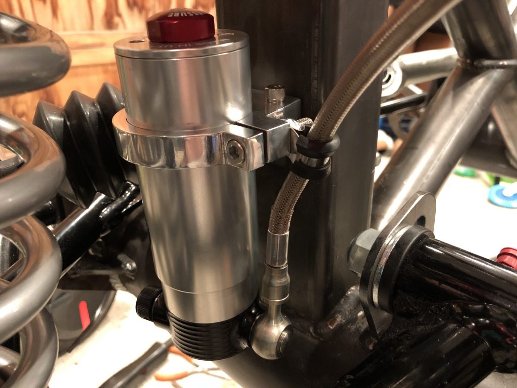
I slipped the strut reservoir in place and tightened down the clamping screw. I then used a cushion clamp to secure the hose to the back side of the clamp.

