Soldered Hazard Light Circuit

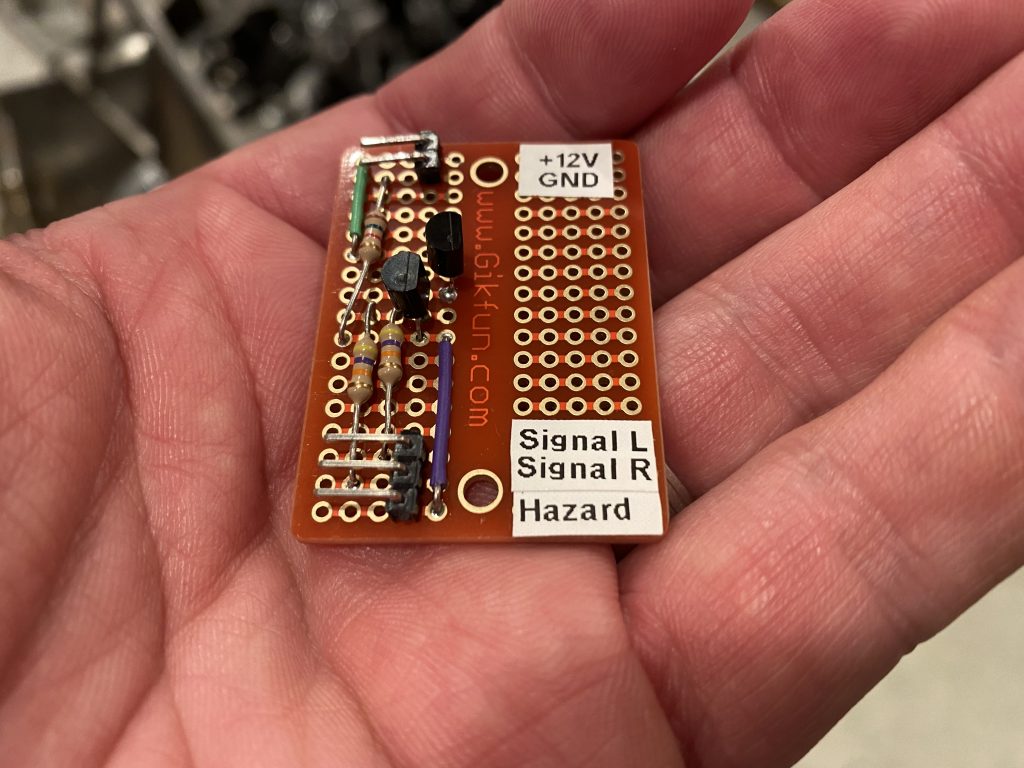
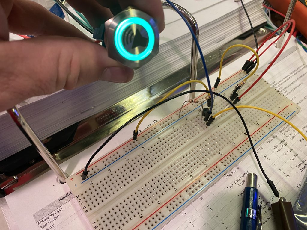
I picked up a handful of these solderable breadboards and soldered up the hazard light circuit with a couple of I/O connectors. Before installing it, I verified the circuit still worked as expected.

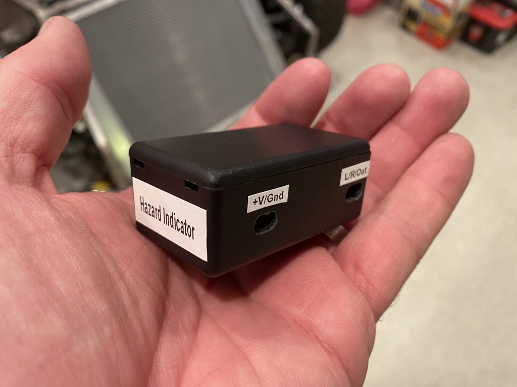
I also picked up some of these small plastic enclosures. I cut some access ports on the side using the mill that align with the connectors and then threw a few labels on it.

Wiring Cleanup

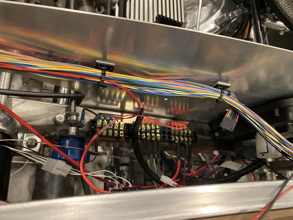
I started trying to organize the wiring a bit and shortening some of the long wires that I had coiled up behind the dash.

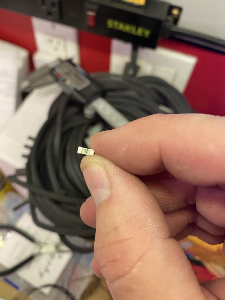
When I powered everything back up though, the indicator lights in the panel weren’t working. Somehow in the process of shortening the wires, one of the power wires coming from the inDASH Max box must have hit the chassis and blew the internal fuse. I opened it up, and it uses these incredibly tiny micro fuses. I verified one of the two had blown and ordered some replacements. The came a couple of days later and I verified that the replacement fuse fixed the problem.

Hazard Circuit

The buttons in the button panel I showed yesterday have LED rings around them that will light up when the corresponding function is turned on. Most of these are pretty simple since there is a single output wire from the front POWERCELL for each of the functions. I tapped into each of these wires and will power these LEDs from them.

The hazards are a different matter though. There’s not a separate output from the POWERCELL for the hazard lights. Instead, the power cell flashes both left and right turn signals in unison. I obviously don’t want the hazard button to flash whenever a turn signal is on; it should only turn on when both turn signals are on at the same time. Essentially, I need an AND gate for 12V signals that is capable of flowing enough current to drive these LEDs.

Fortunately, that’s a pretty trivial circuit to build with a couple of NPN transistors and a few resistors. The two upper yellow wires represent the left and right turn signal wires. When both are plugged in to the power rail adjacent to the red line, the LEDs turn on, but if either wire is removed from 12V (as would happen if only a single turn signal is turned on), the LED is off.

I have some small breadboards coming in a couple of days and will solder up this circuit to be installed in the car.

Prototype Button Panel and Lighting

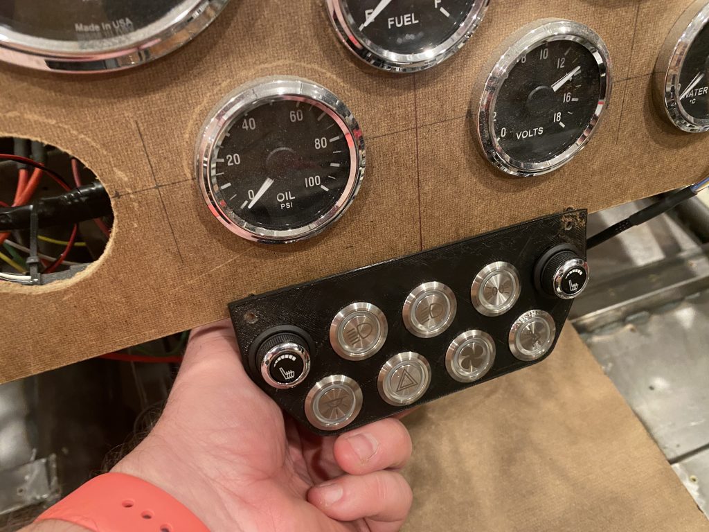
I 3D printed a prototype button panel. Ultimately, I’ll fabricate something that sits below the dash and is recessed somewhat. That will make it easily reachable, but not in the way of shifting.

The final button arrangement hasn’t been determined, but the initial layout places the seat heater controls on the top row at each end and all exterior lighting between them. Starting from the right is a button for the parking lights. The middle light will turn on the headlights (which will also turn on the parking lights if they’re off). Finally, the left button is the high/low beam toggle. I considered putting these near the steering wheel somewhere, but any location along the bottom of the dash is obscured by the steering wheel. Any higher location is easily visible, but more awkward to reach.

The bottom row has an assortment of buttons. Starting from the left, the first button is for the interior lights. These will come on automatically when the alarm is disarmed or when the car is turned off. The second button is the hazards. The third button is the fan override, and the final button is the passenger eject button.
I hooked up all of the exterior lights to verify they worked, and ran into an odd behavior. When the right turn signal was turned on, it worked correctly, but when the left turn signal was turned on, both left and right turn signals flashed dimly.
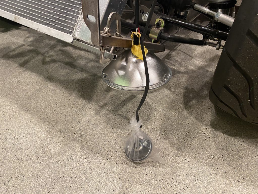
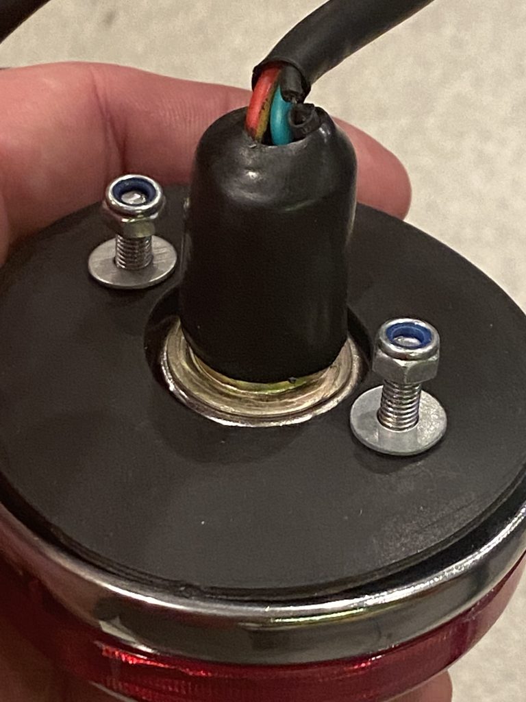
When I diagnosed the issue, I found out that one of the tail lights had a broken ground wire. This was causing power flowing into the turn signal to flow back through the brake light filament (through the shared ground in the bulb) and into the brake light of the opposite tail light. If it’s easy to fix, I’ll do that; otherwise I’ll call Factory Five to get a replacement.

Update: the wire broke right at the solder joint. I removed the heat shrink and re-soldered the ground, and everything now works correctly.
First Drive!

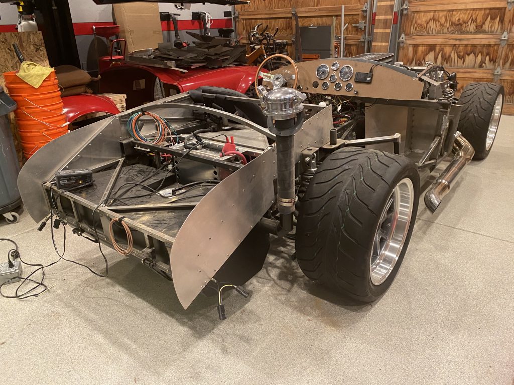
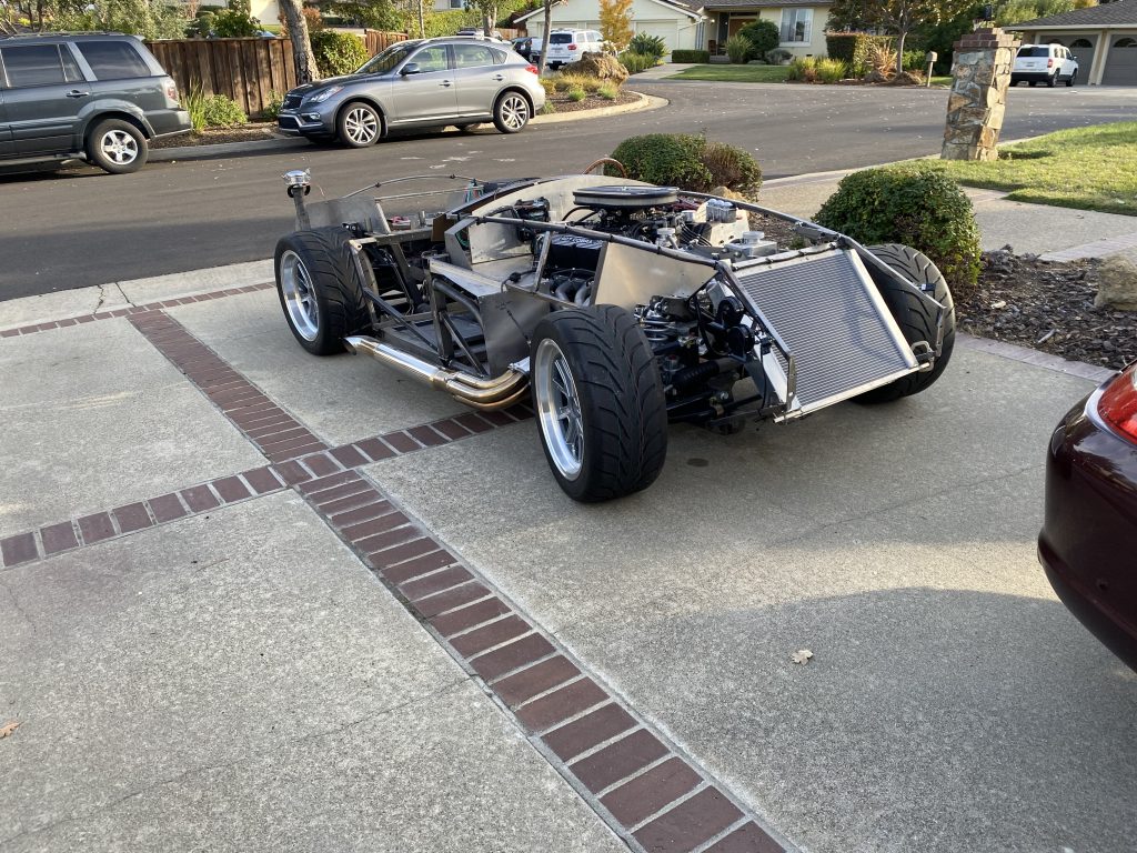
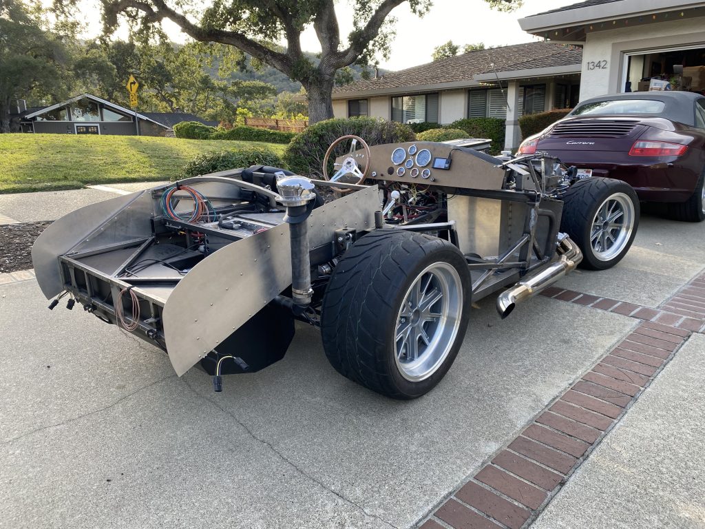
I buttoned up all the loose items on the car in preparation for taking it for its first test drive, then removed it from the dolly and sat it on the ground.

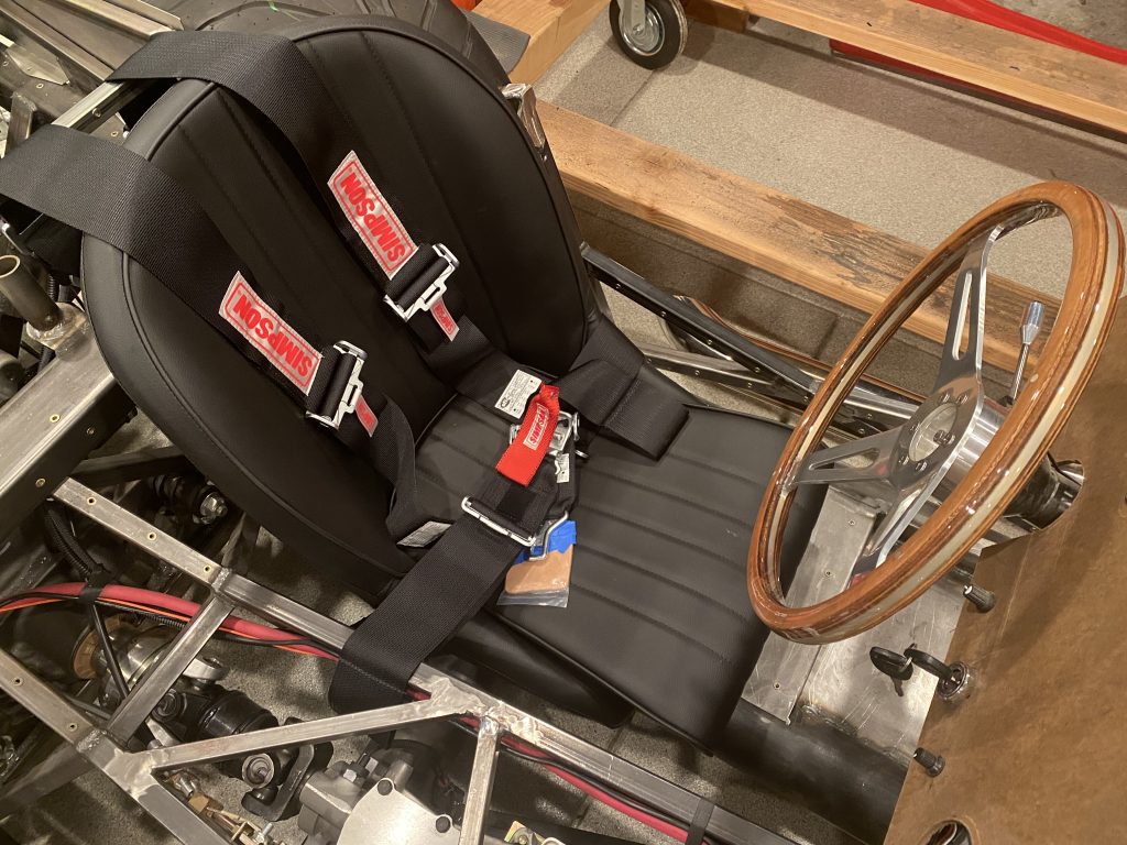
I also installed the driver’s seat, seat belts, and steering wheel.

I fired up the car and pulled it out into the driveway where I immediately ran out of gas. After a quick trip to the gas station, it fired right back up.

I drove it around for a bit to test the clutch, brakes, and throttle. Everything works as expected.

It will be incredibly handy to be able to move the car under its own power to turn it around and move it between bays. Also, it will be nice to be able to pull the car into the driveway when I need to run the engine to avoid filling the garage up with exhaust.

Installed Hydraulic Clutch

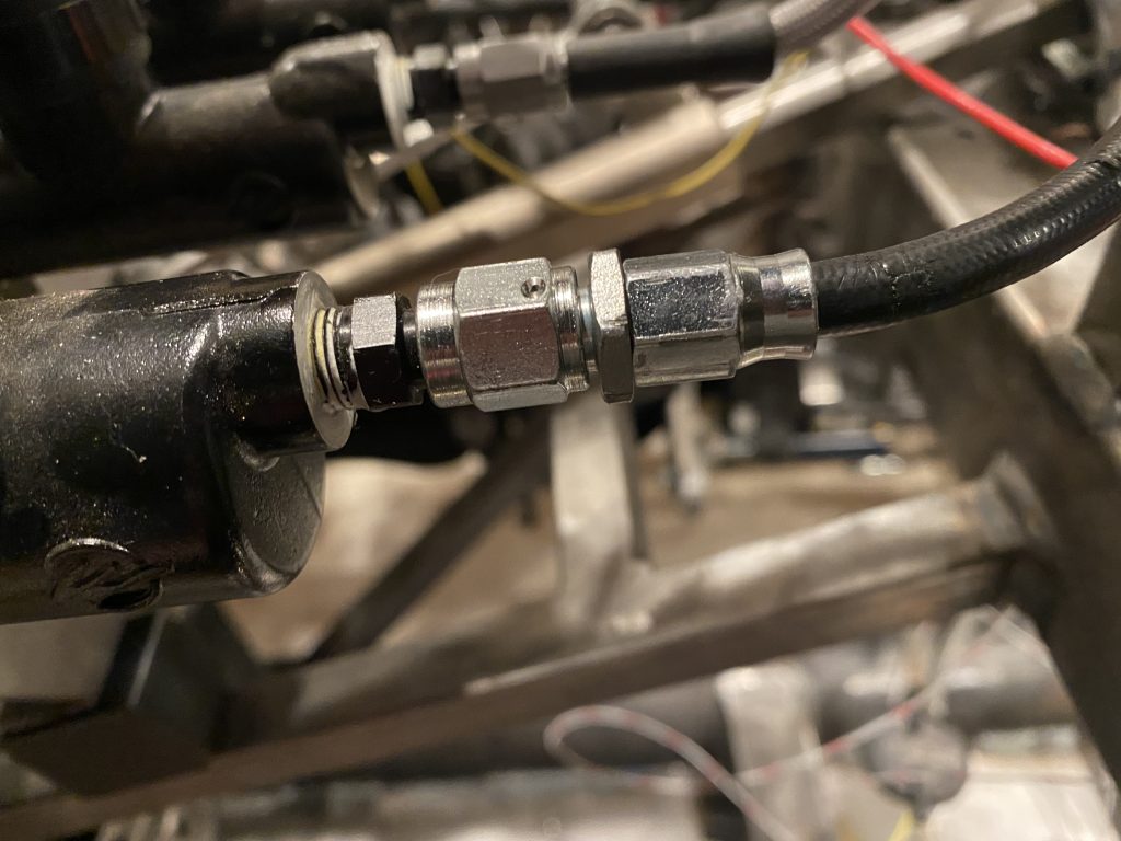
One of the few things left to do before I can go-cart the cart is to get the hydraulic clutch working. I cut the 3/16″ hose to length and installed the hose end. These are always a pain in the ass, but I think this is the last one I need to do in the car.

After installing it, I filled the reservoir with DOT 4 brake fluid and bled the system. I needed to adjust the clutch pedal to get a little more throw in order to release the clutch. The master cylinder has an adjustment on the pushrod which is easy to reach right now. I hope I never have to adjust them once the body is on the car because all of the access with be from below or through a small access panel in the engine compartment.

The other thing I did today was get the engine running again. It’s been quite awhile since it ran, so I disconnected the ignition coil and cranked until I had oil pressure. When I reconnected the ignition coil, it fired right up and ran great. I let it run for a bit to warm up and then revved it for a bit. The FiTech still doesn’t manage the fuel properly when reducing throttle after revving it, so it tends to die. I’ll need to dig into the config to see how to address this.

Installed Mill and Lathe in the Shop

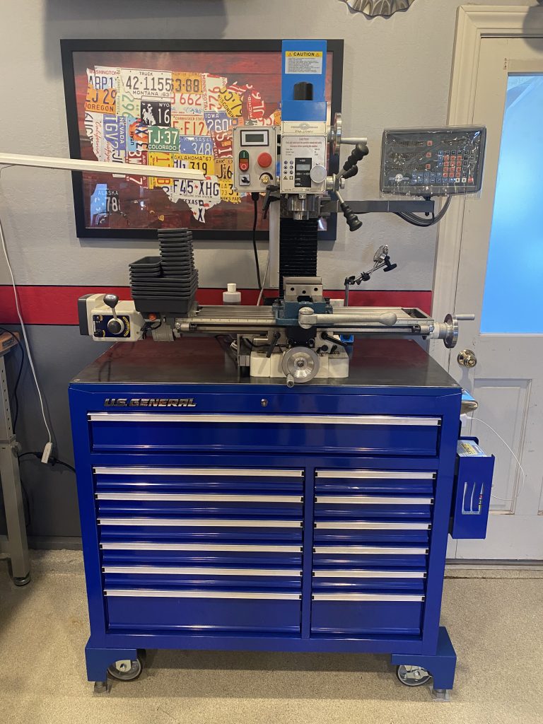
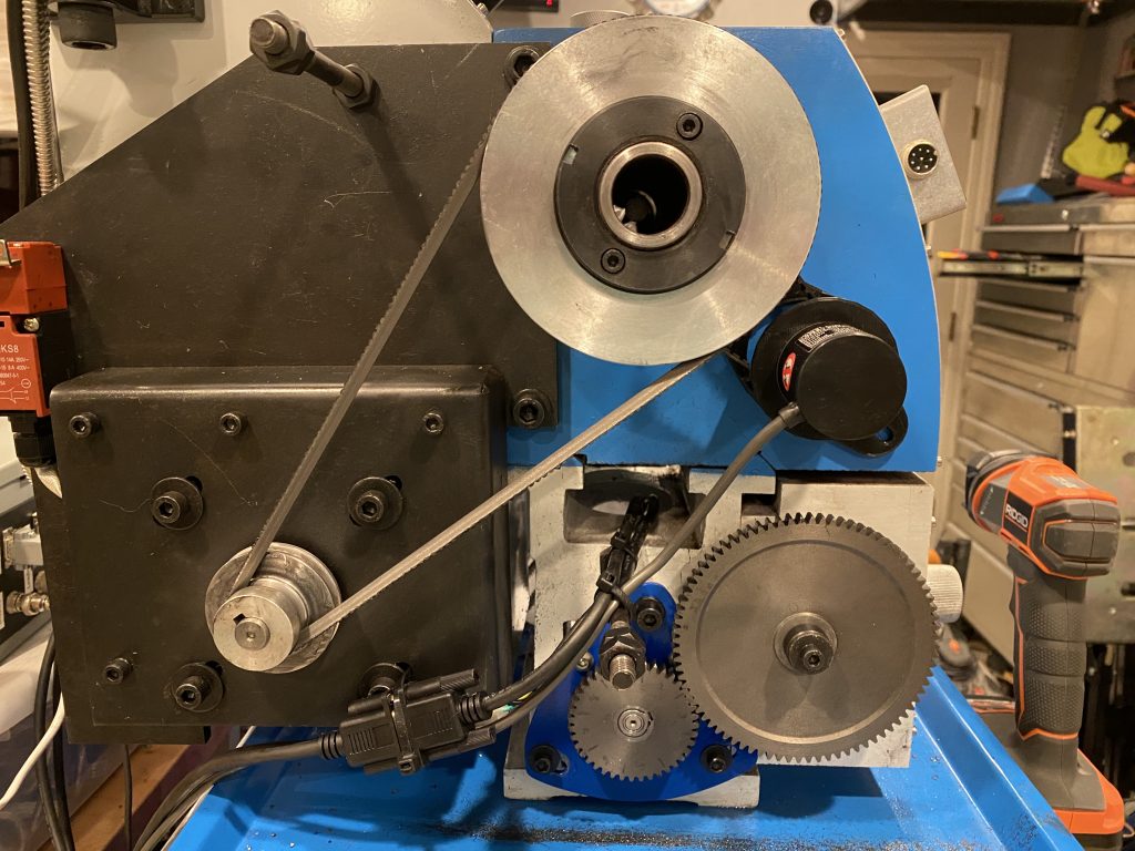
In preparation for resuming work on the car, I wanted to improve the tooling I have for metal work. I was fortunate to have a friend give me a Precision Matthews PM-25MV bench top mill he was no longer using. I added a couple of upgrades to the mill including a power feed on the x-axis and a quill stop and quill lock (not pictured).

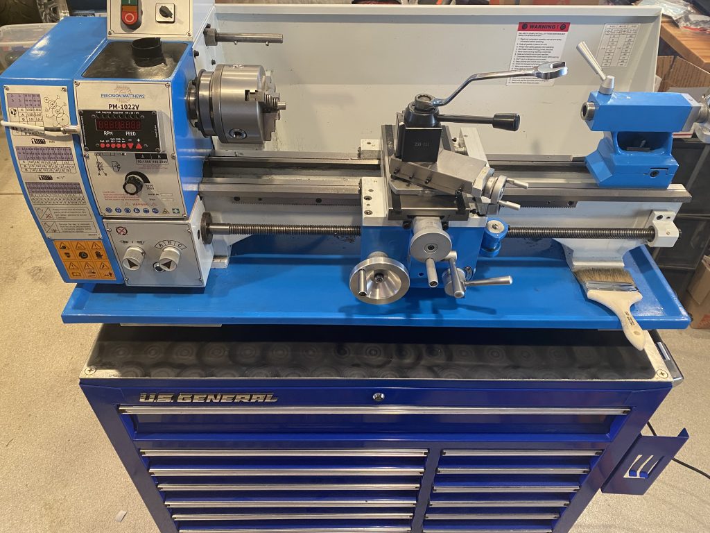
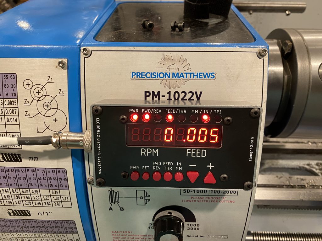
I also decided to add a lathe to the shop since I’ve already needed a lathe for a few tasks on the car. I don’t have a ton of space, so I picked up a Precision Matthews PM-1022V lathe and mounted it on an identical tool box.

These small lathes have relatively simple gearboxes, so they use a set of change gears that must be swapped to change the feed rate or for any threading operation. I didn’t like the thought of having to mess with that, so I installed an electronic lead screw. This was designed by James Clough but requires a custom installation on each machine. It uses an optical encoder to read the spindle position and then a microcontroller controls a servo to drive the leadscrew.

This lets you switch between forward/reverse, feeding/threading, and inch/mm units at the touch of a button and change the feed rate on the fly as well as simply selecting the threading pitch on the screen (for both SAE and metric threads). This should be a nice upgrade for this little lathe.

Reinstalled Firewall and Throttle Linkage

It seems like it’s been forever since I worked on the car, but home remodels and work have gotten in the way. The garage is finally back to a reasonable shape where I can work on the car though, so I pulled it out from under the lift and picked up where I left off.

I drilled and added rivnuts to the 2″ square cross tube every where I could reach, but the engine is in the way for all of the holes through the center. I’ll have to install those rivnuts after the engine is removed for chassis finishing.

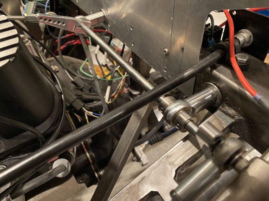
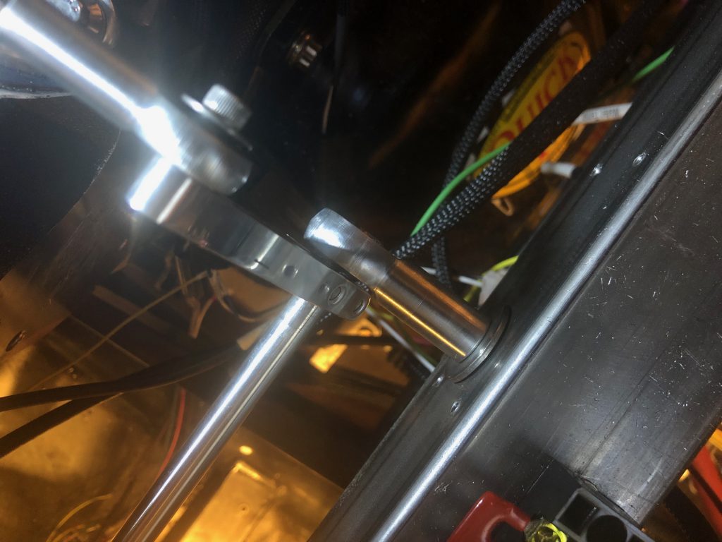
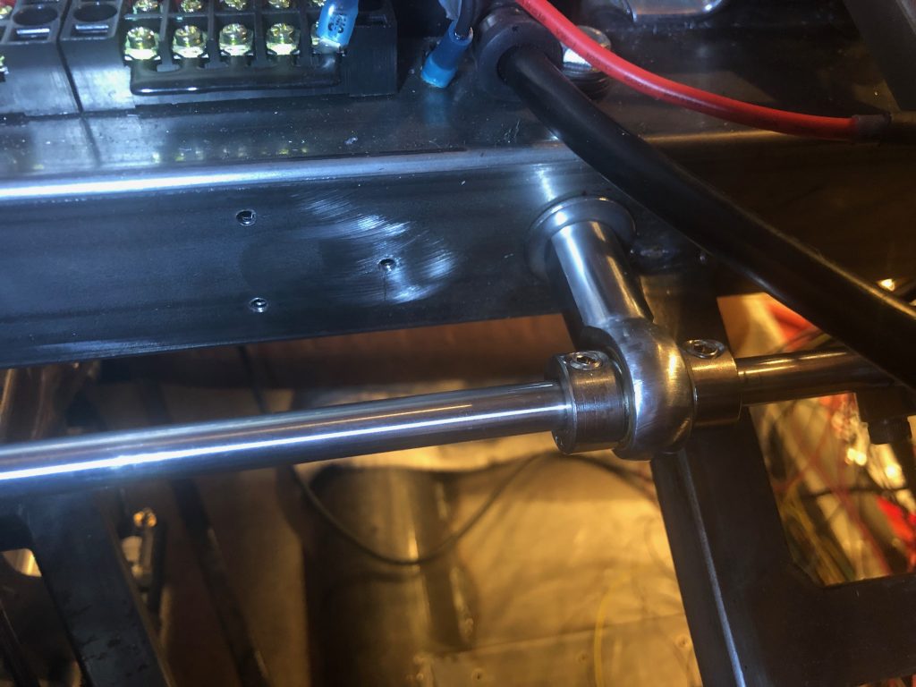
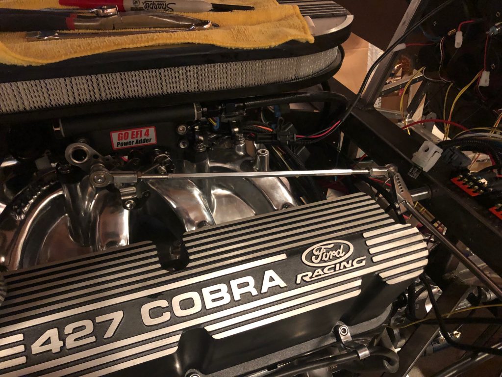
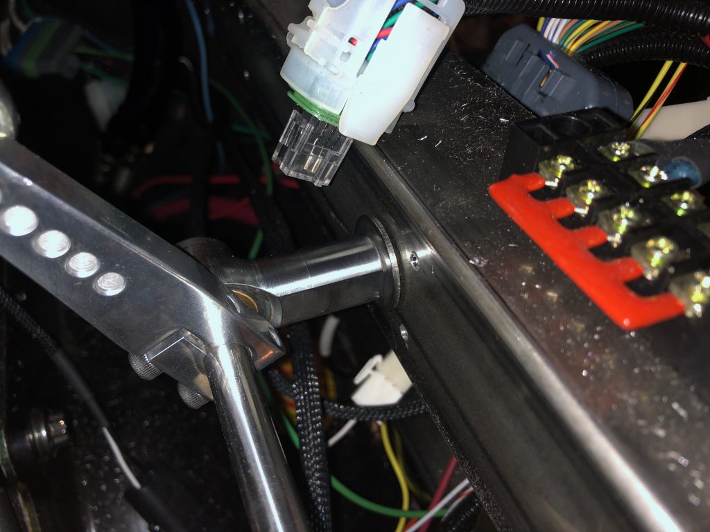
I reinstalled the firewall and then installed the two rod end bearings that support the throttle shaft, then installed the throttle arms and connected the linkage. The throttle arm that connects to the engine is sitting at an unusual angle, but this is intentional. When we first start driving the car, I want to limit the throttle travel since this engine is such a beast. I set up the throttle linkage to only give us about 1/2 throttle to start with and I can adjust this over time as we get used to driving it.

Finished Throttle Linkage

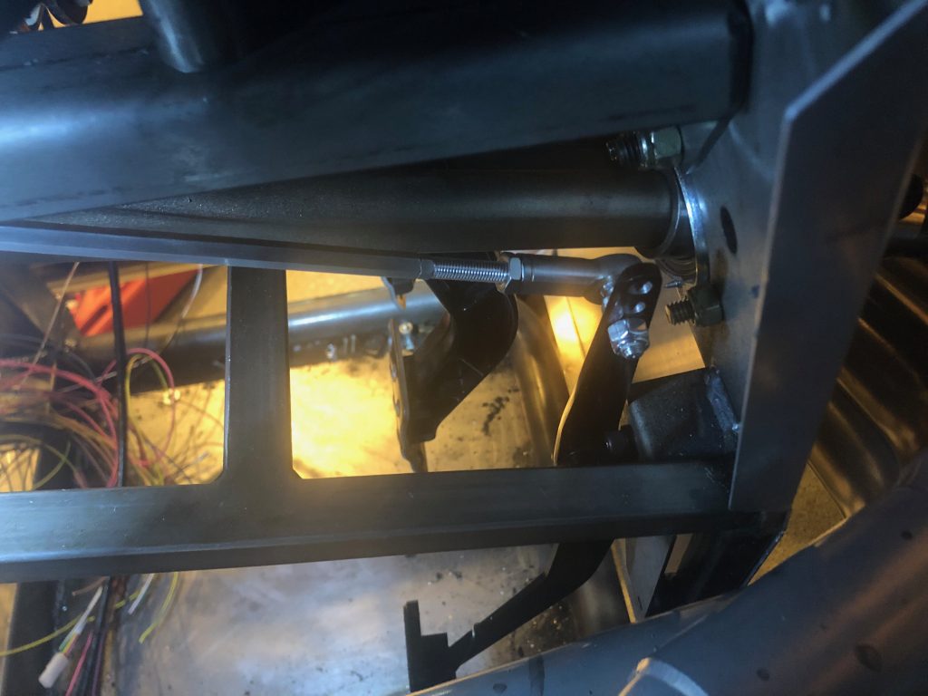
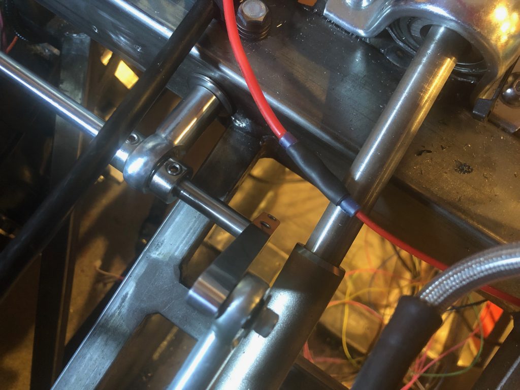
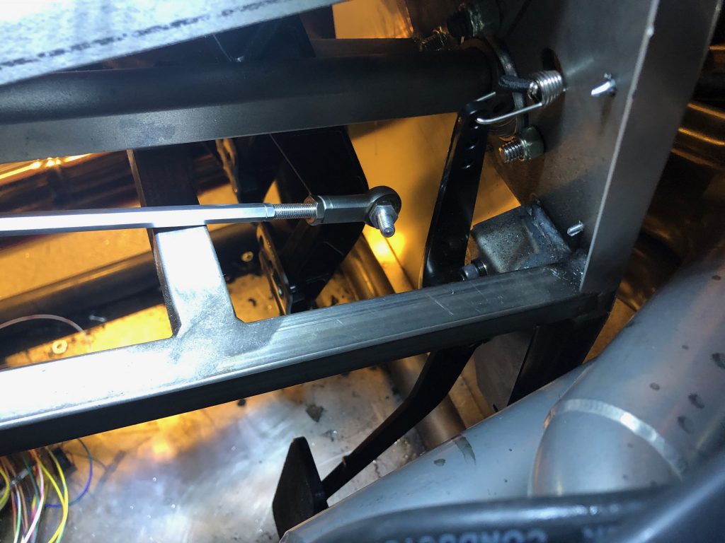
I pulled out the accelerator pedal and drilled and tapped the upper arm for the 1/4-28 stud on the rod end bearing. Since there is a pedal box support that’s partly in the way, I installed the rod end bearing on the left side of the upper arm.

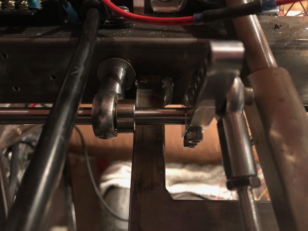
Unfortunately, that didn’t move the linkage far enough to the left to clear the pedal box support completely, so I also decided to slide the pivot shaft to the left a bit to increase the clearance. The pivot shaft now just sits flush with the right edge of the inner rod end bearing on the firewall.

To prevent the shaft from moving either direction, I installed the other shaft collar on the other side of the outer rod end bearing on the firewall.

This moved the pivot shaft and outer linkage an additional 3/8″ to the left. It’s pretty close to the steering shaft now, but still has plenty of clearance.

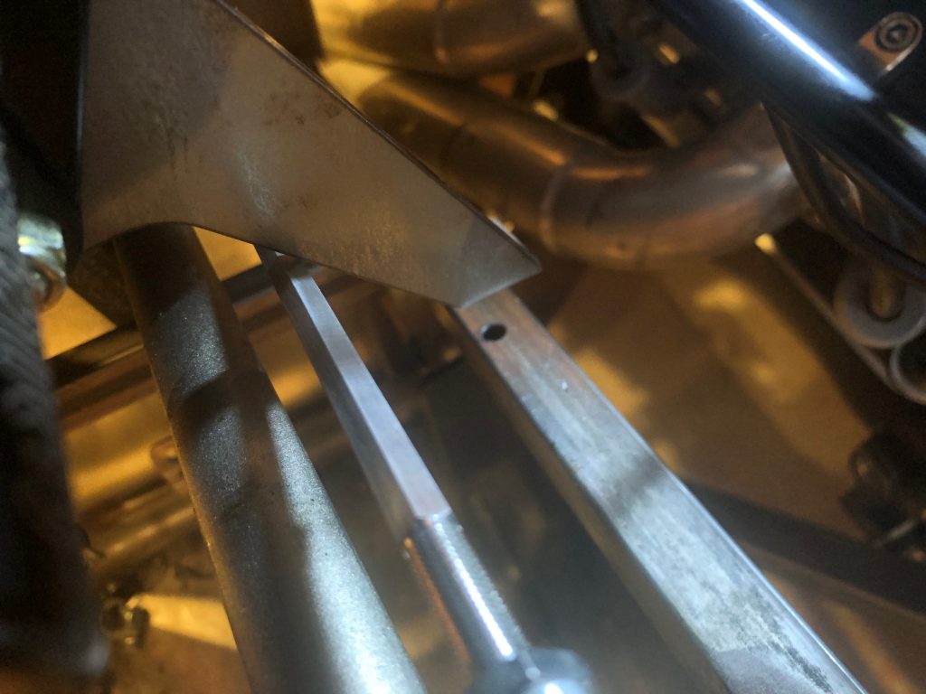
The linkage from the accelerator pedal upper arm to the pivot shaft arm now clears the pedal box support. It’s still pretty tight, so I may relieve the support slightly to prevent any touching, but at least I don’t need to remove a lot of material now to provide this clearance.

Started Installing Mechanical Throttle Linkage

I started installing the throttle linkage tonight. One disadvantage to installing the linkage directly to the 2″x2″ tubing is that it causes the linkage to sit at an angle. I tried installing it to the lower portion of the throttle arm which changes the throttle action from pull-to-increase to a push-to-increase, but the geometry made it nearly impossible to hit full throttle. By installing it to the upper portion of the throttle arm with a the pull-to-increase throttle action, it’s easy to move it through the full throttle range.

I installed two 3/8″ rivnuts into the 2″x2″ square chassis tubing. The first one is almost directly behind the throttle arm so that the linkage is parallel with the valve covers. I used some 2″ pieces of 3/8″-24 stainless all-thread to attach the rod end bearings to the tubing. The throttle linkage is connected to a throttle arm from Speedway that attaches to a 12″ pieces of stainless rod.

The other end of the stainless rod goes through the second rod end bearings that’s installed inside the driver’s footbox. There is a second Speedway throttle arm here with another linkage to the accelerator pedal.

I haven’t hooked up the forward end yet because the throttle pedal is drilled for #10 screws and I inadvertently ordered a rod end linkage with a 1/4″ stud. I might try drilling this out before ordering more parts.