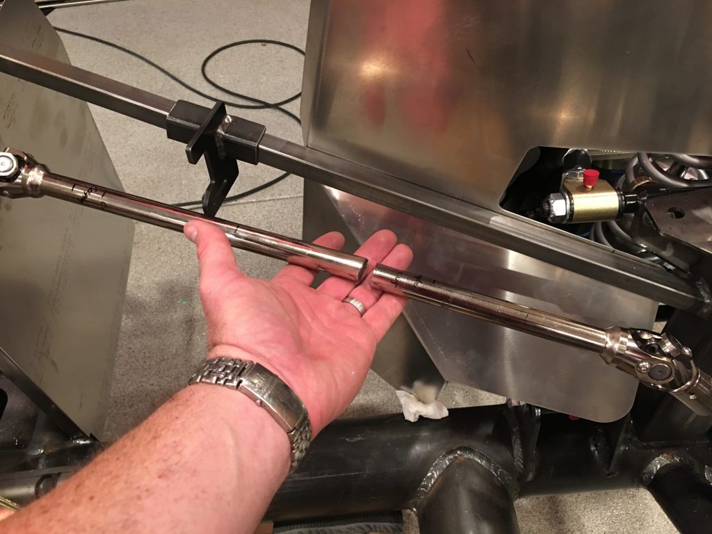
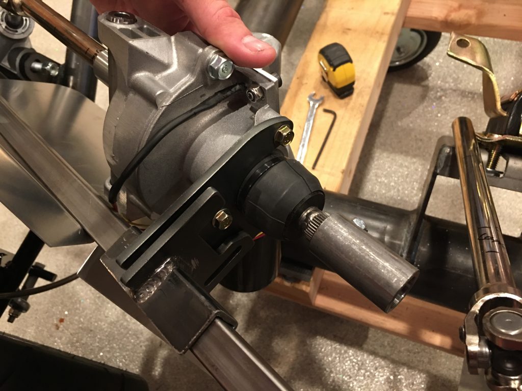
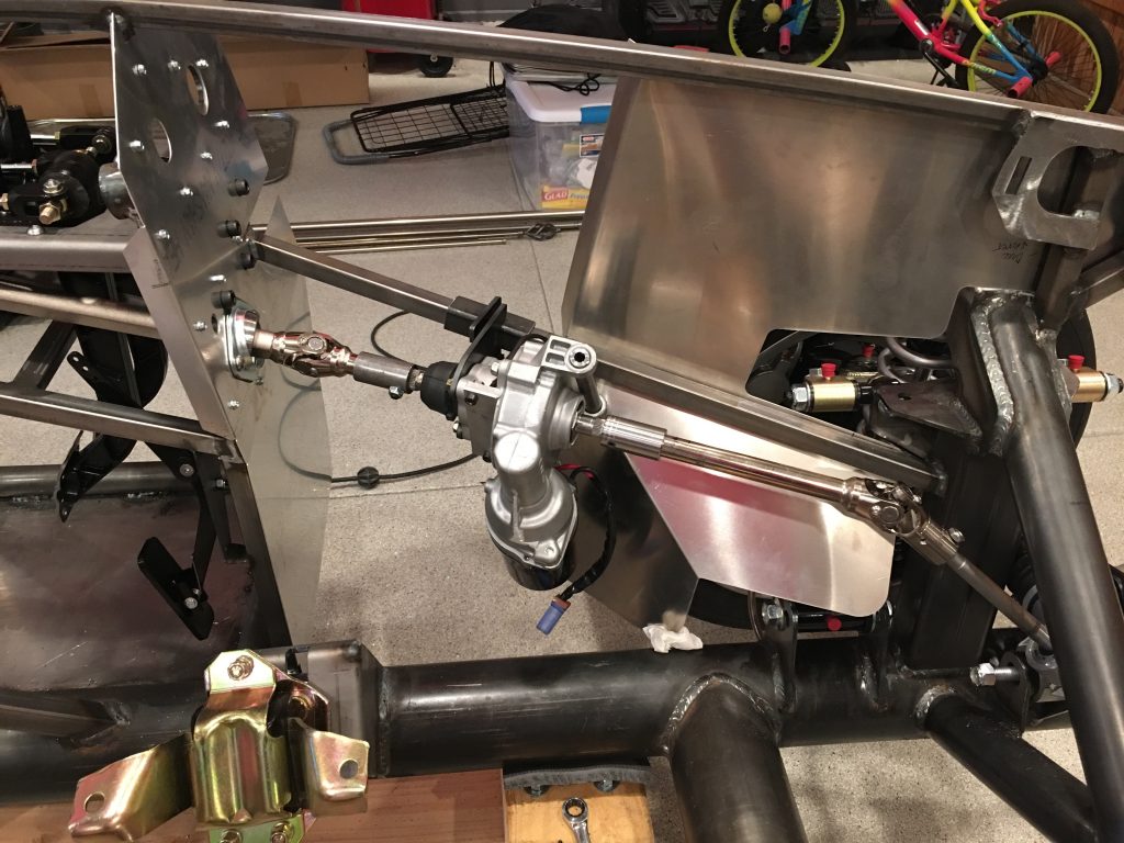
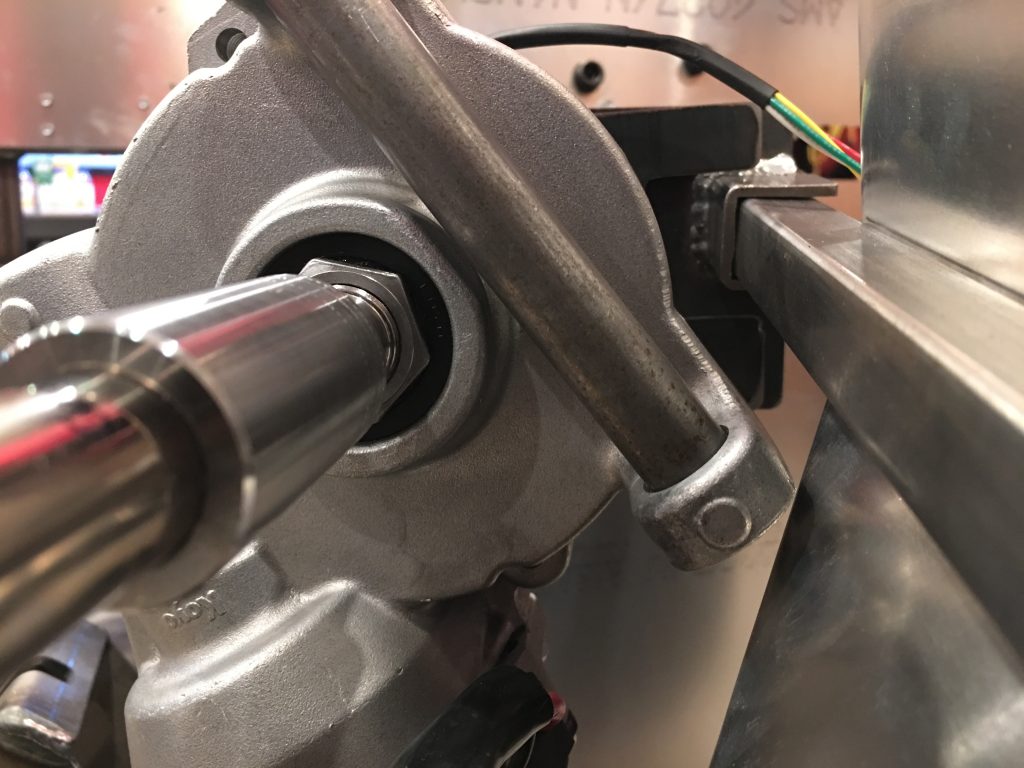
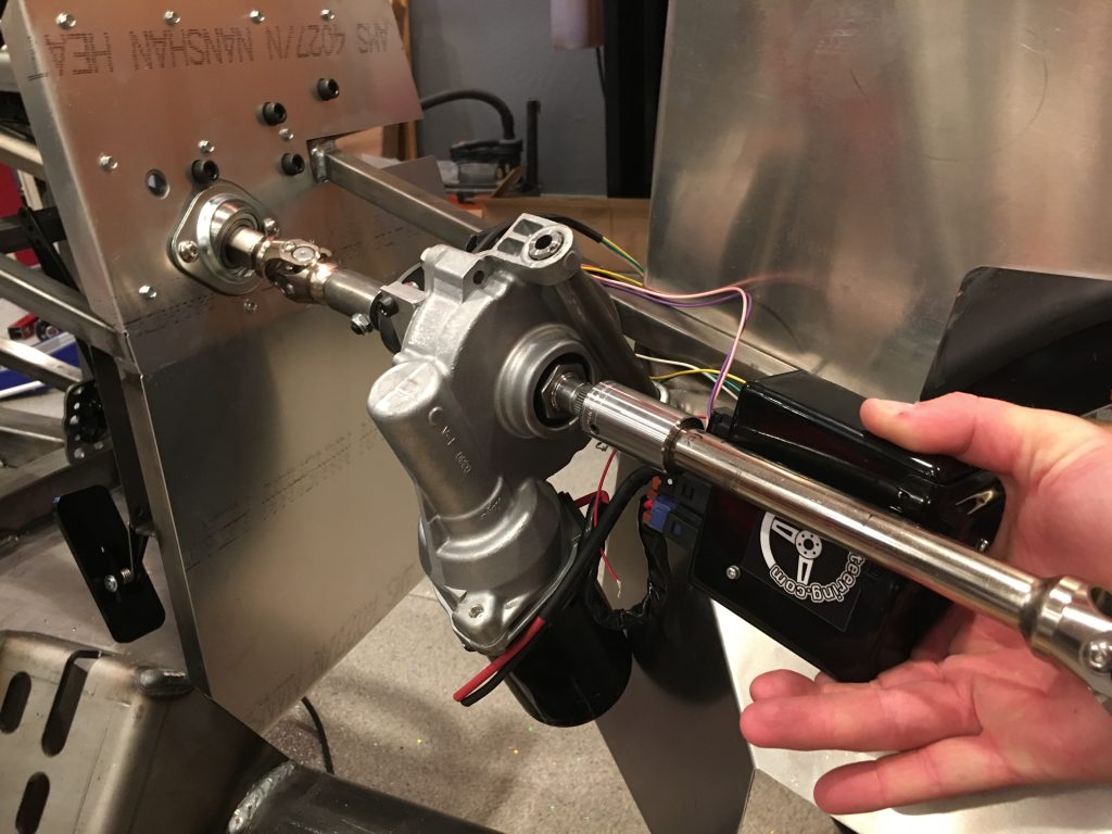
The first step in installing the electric power steering (EPS) system is to cut the steering shaft. I ended up moving the electric motor back almost as far as it could go and then taking some measurements from the engine mount to ensure I’ll have plenty of clearance.
I just started with a single cut in the shaft because this would let me adjust the motor up or down from there, but it looks like this spot will work absolutely perfectly. I really can’t go back any further because I’d hit the steering shaft u-joint and I’d interfere with the exhaust headers which exit just aft of here.
After determining everything will fit nicely, I cut the other end of the shaft and test fit everything.
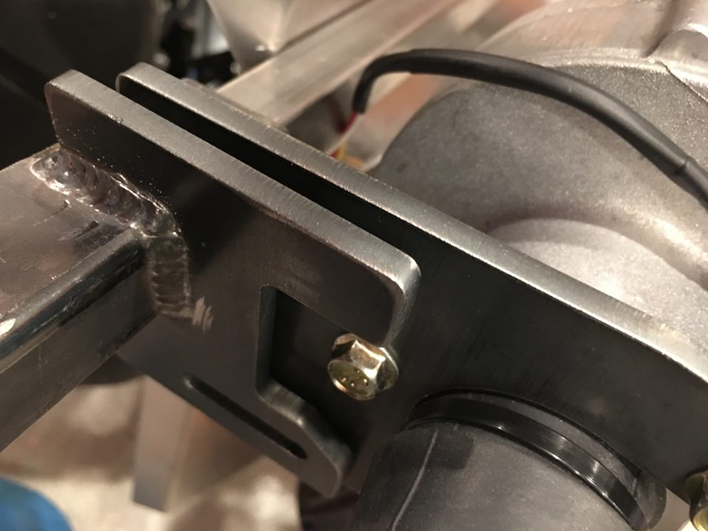
The bracket that came with the system isn’t welded at the right angle to allow the motor bracket to bolt up to it. I’ll let Erik know, but I’ll probably just cut and reweld this myself.
The motor clears the F panel by over 1/8″. This bracket isn’t used in this application, so I may just cut it off.
After hunting around for a good place to mount the EPS controller, I decided to mount it to the 3/4″ tubing behind the steering shaft. There’s nearly 1/4″ of clearance between the shaft and the controller, and it’s really out of the way here. The challenge is that there are only two threaded bosses on the EPS controller and they’re at an odd angle. I need to be able to access the screws later in case the controller needs to come out. Mounting it here lets me fabricate a simple bent steel bracket and easily access the mounting screws if necessary.
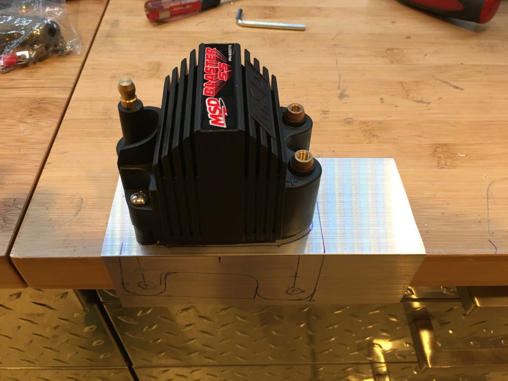
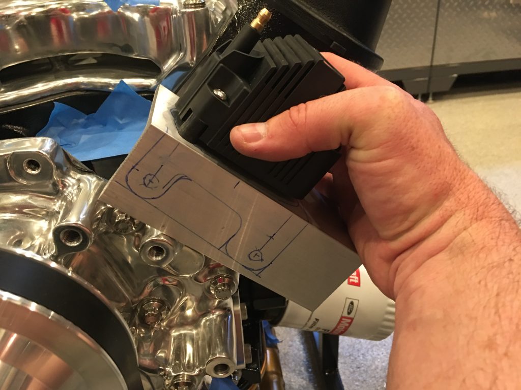
I ended up deciding to mount the ignition coil to a custom bracket that will bolt to the front of the water pump. I had a piece of scrap aluminum angle, so I took some measurements and laid out the shape of the bracket.
Once I cut out the bracket, it will bolt to the front of the water pump using these two bolts. This should clear everything around it and provide a nice, short run from the coil to the distributor.

