Engine Setback

Well, I certainly wasn’t expecting to see this sight again for a long time! What happened you ask? Read on…

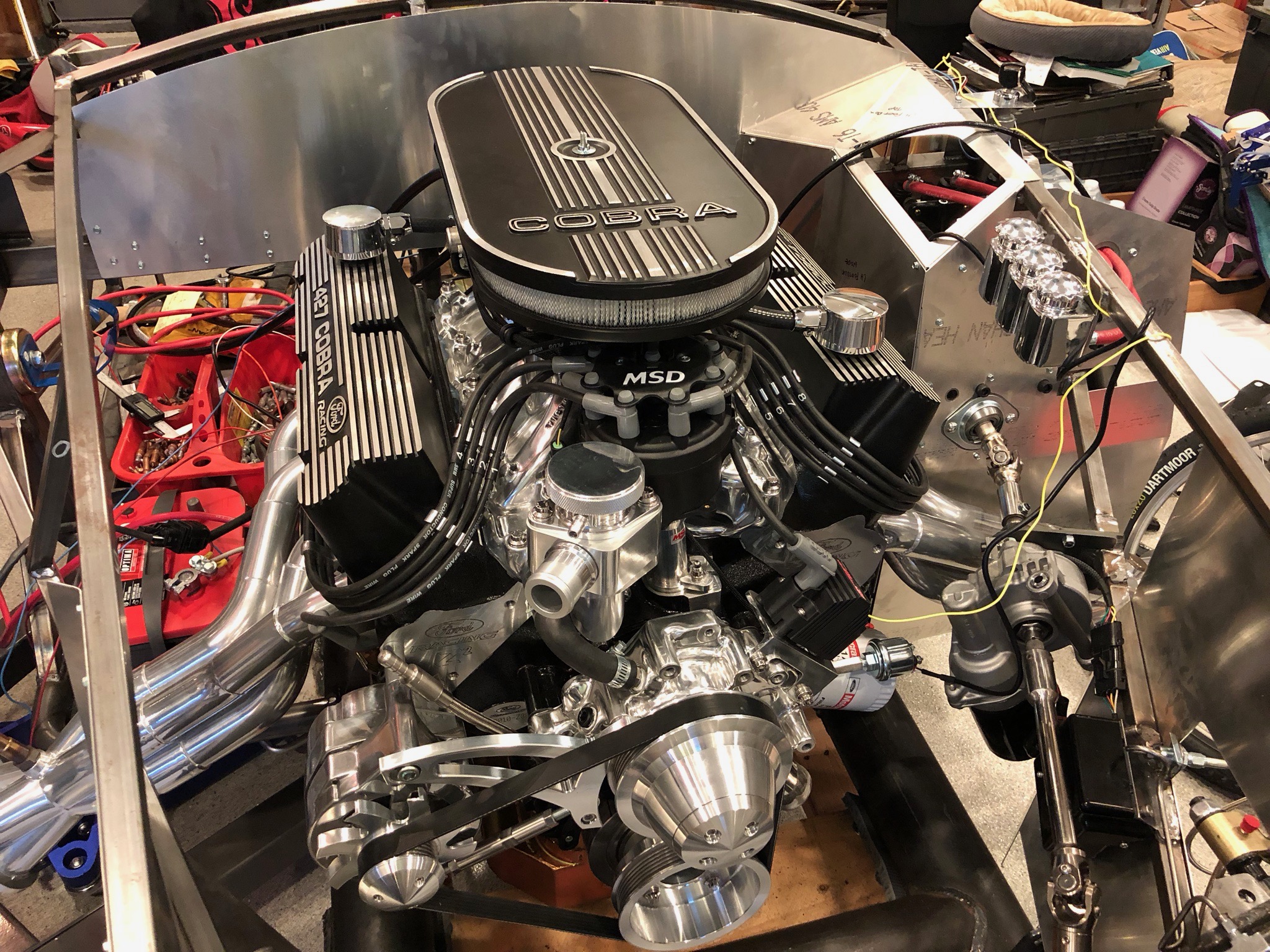
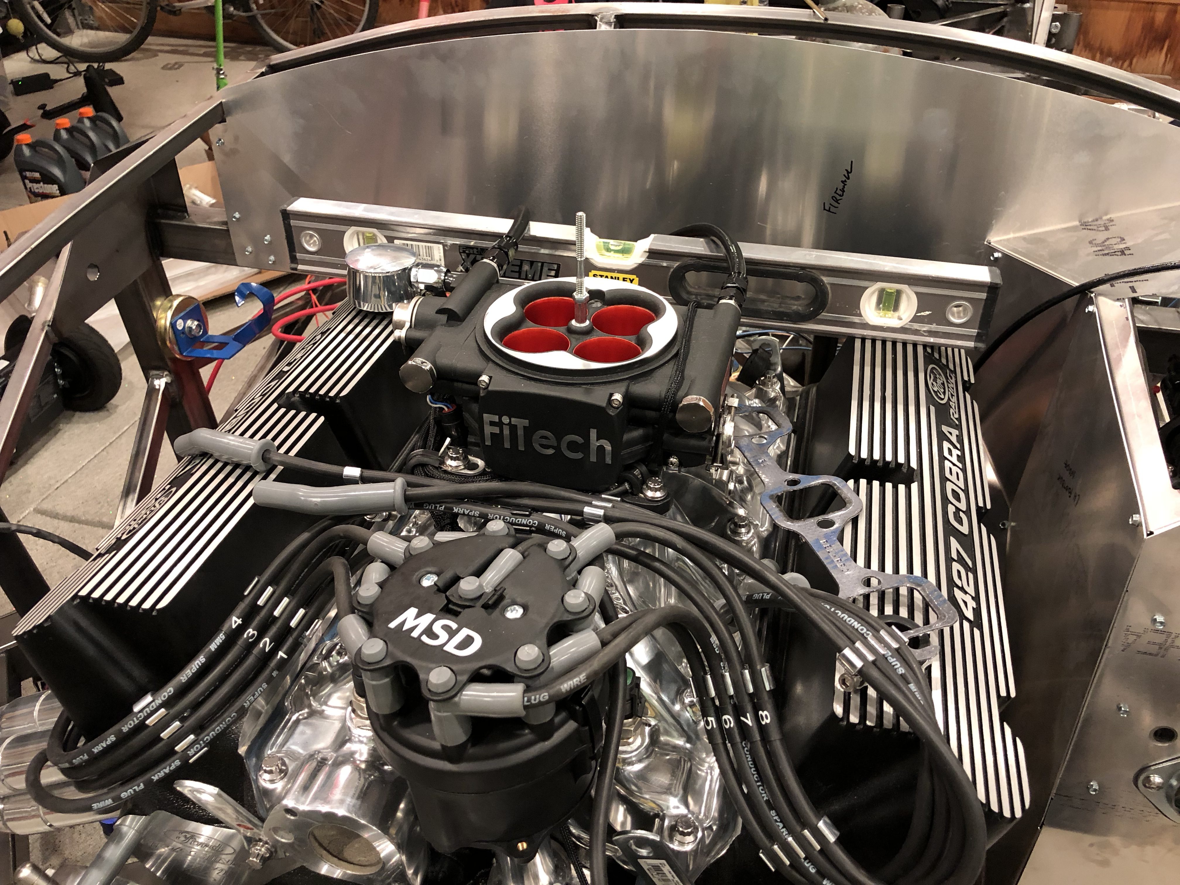
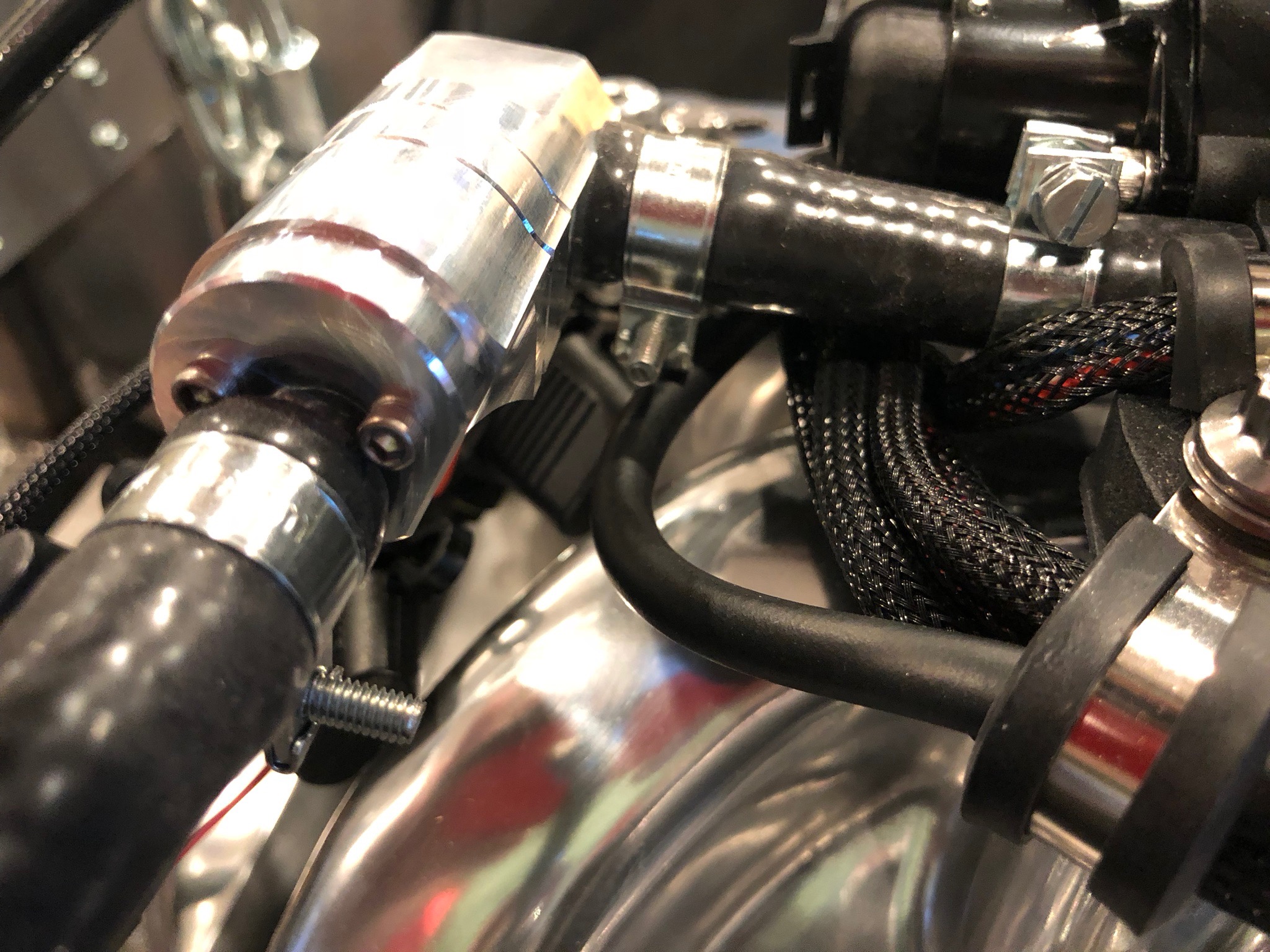
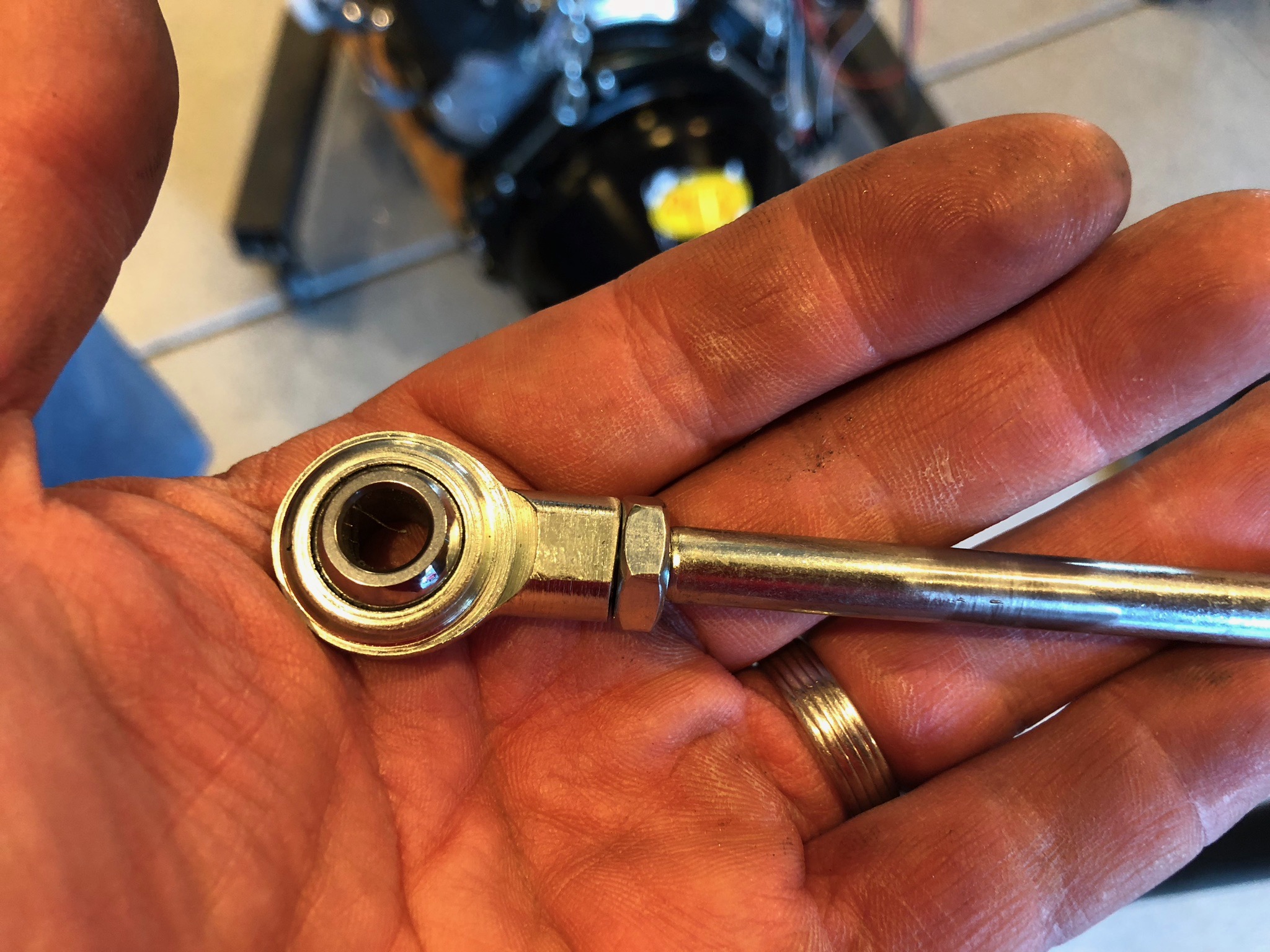
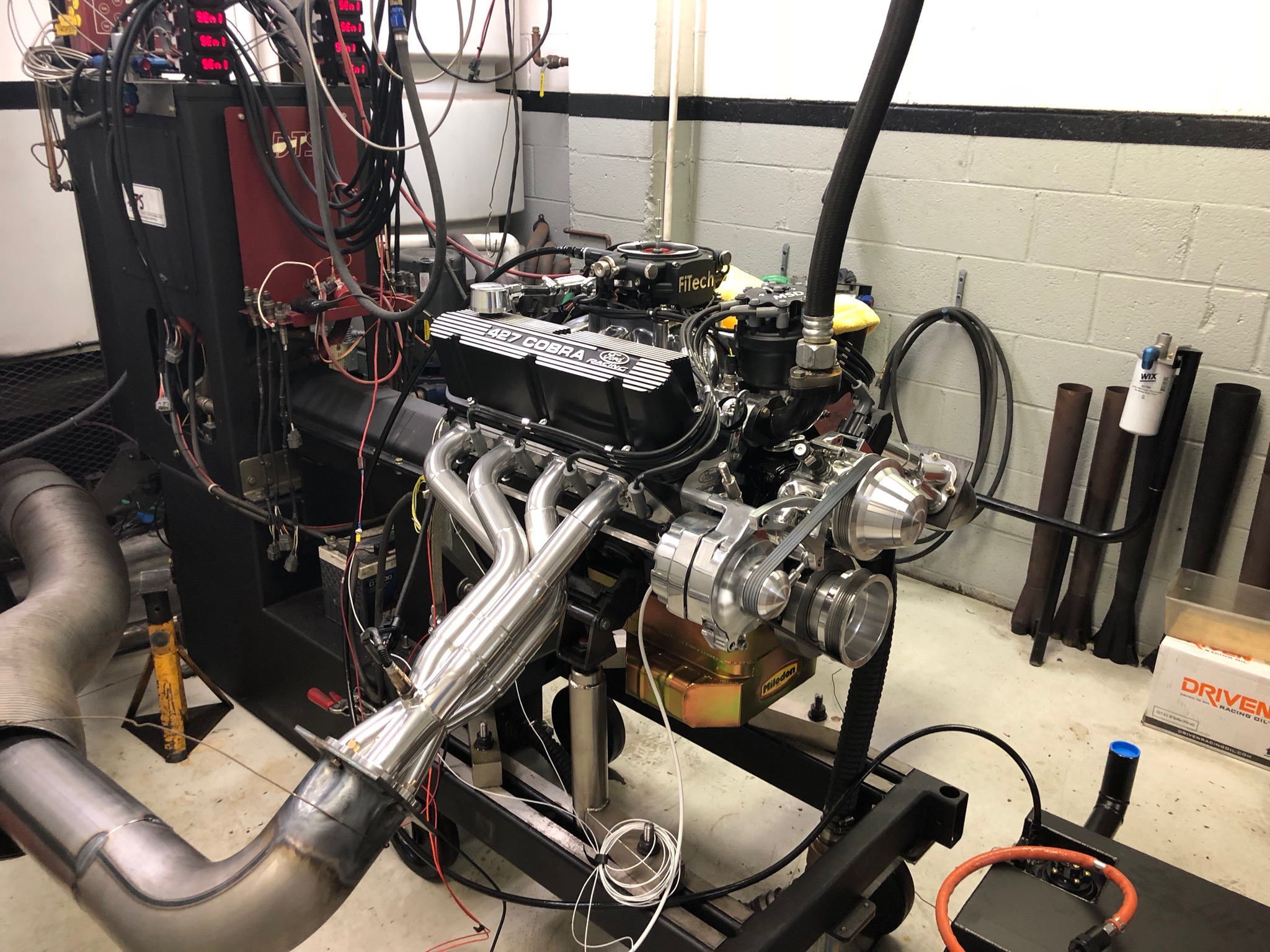
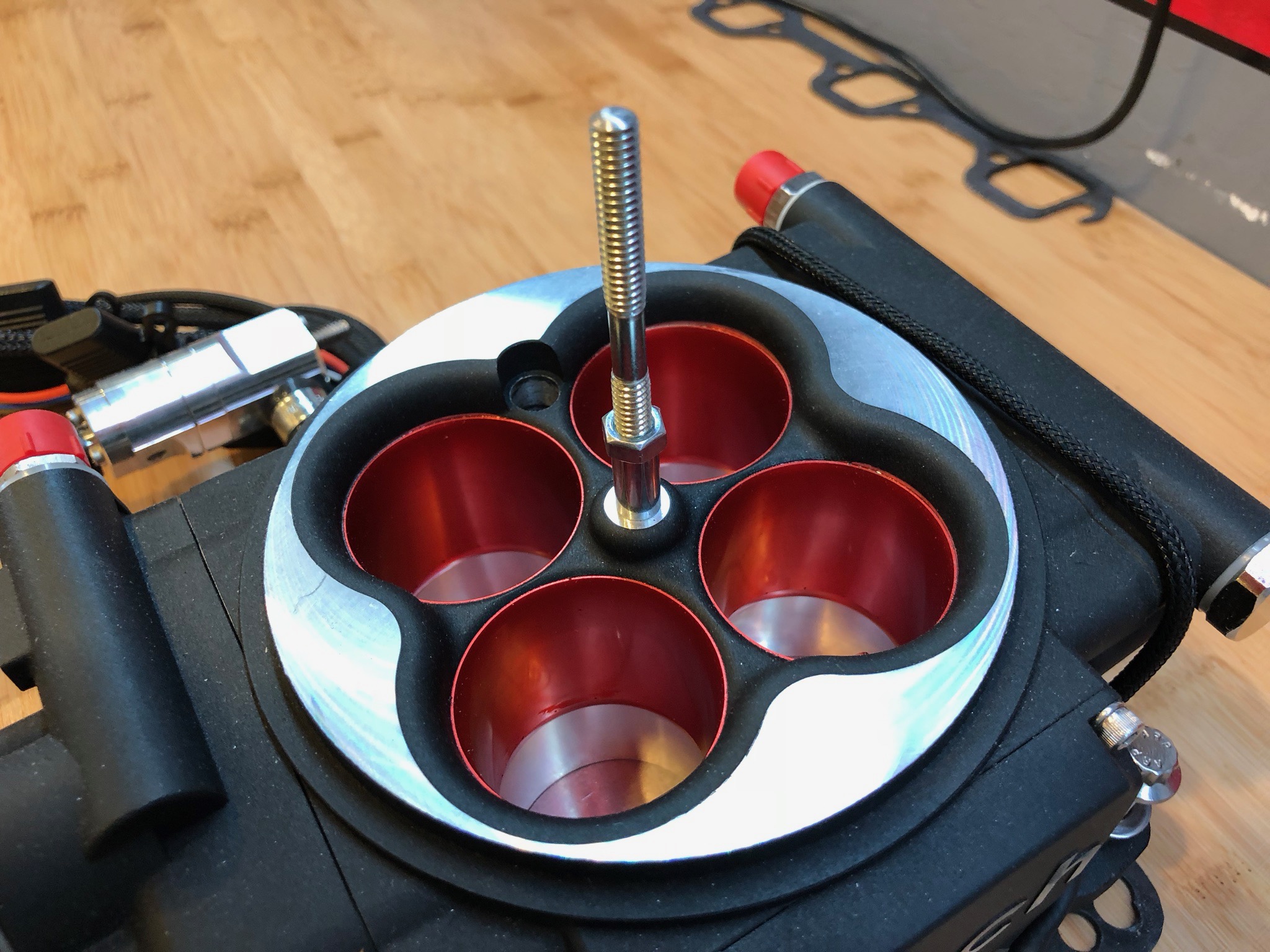
Here was one of the shots I took from the first run of the engine at the dyno shot. The owner of the shop encouraged us to run the engine without the air cleaner to really find out how much power it would make. If you look really close, you can see an extra nut on top of the shaft sticking out the top of the throttle body. That nut is installed to provide a backing surface for the upper half of the air cleaner (so the upper half is clamped between that nut and the outer wing nut). When the air cleaner is not installed, that nut is free to spin on the shaft.

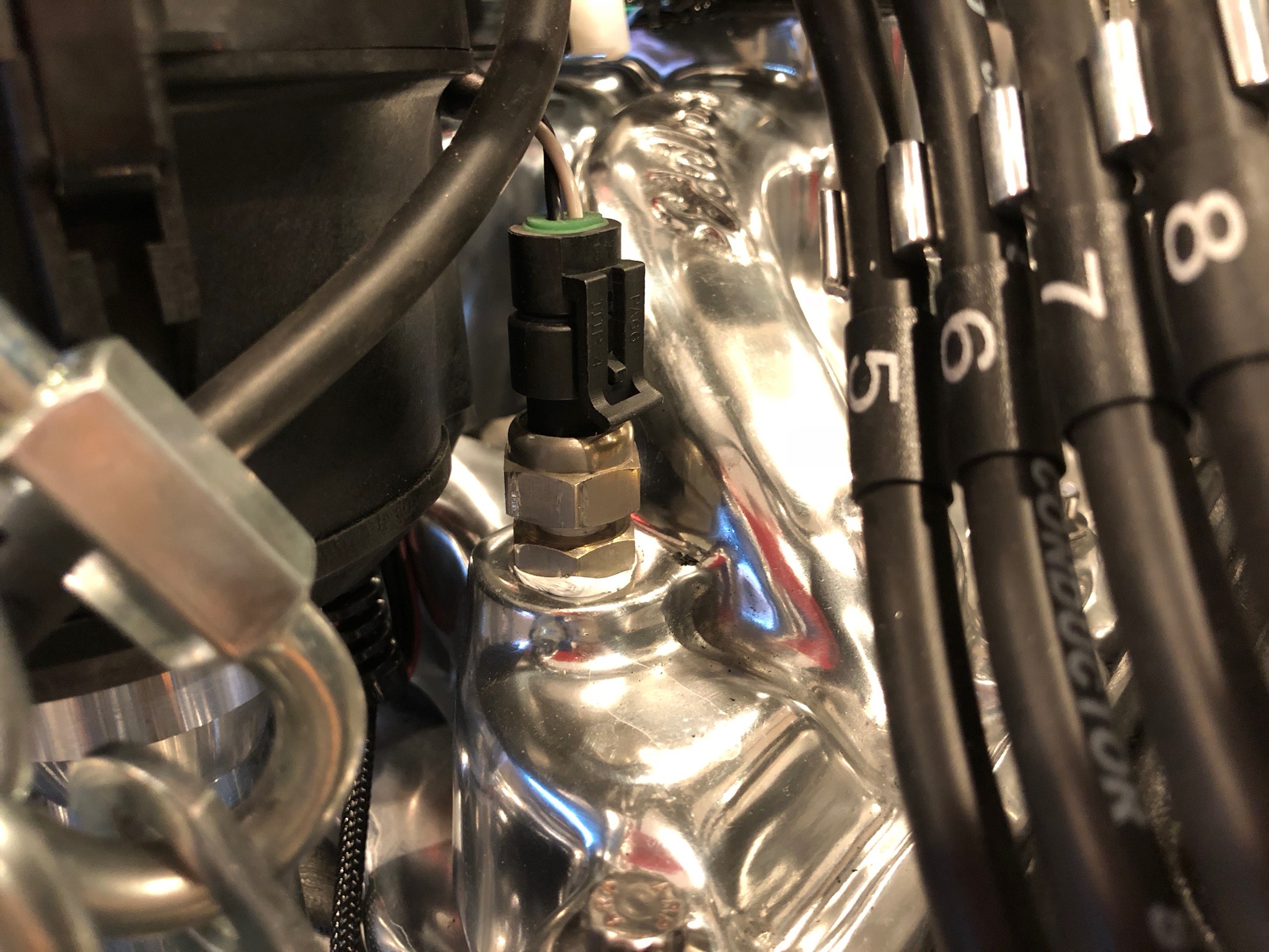
Here’s one of the first shots of the engine after it came off the dyno; notice anything missing?

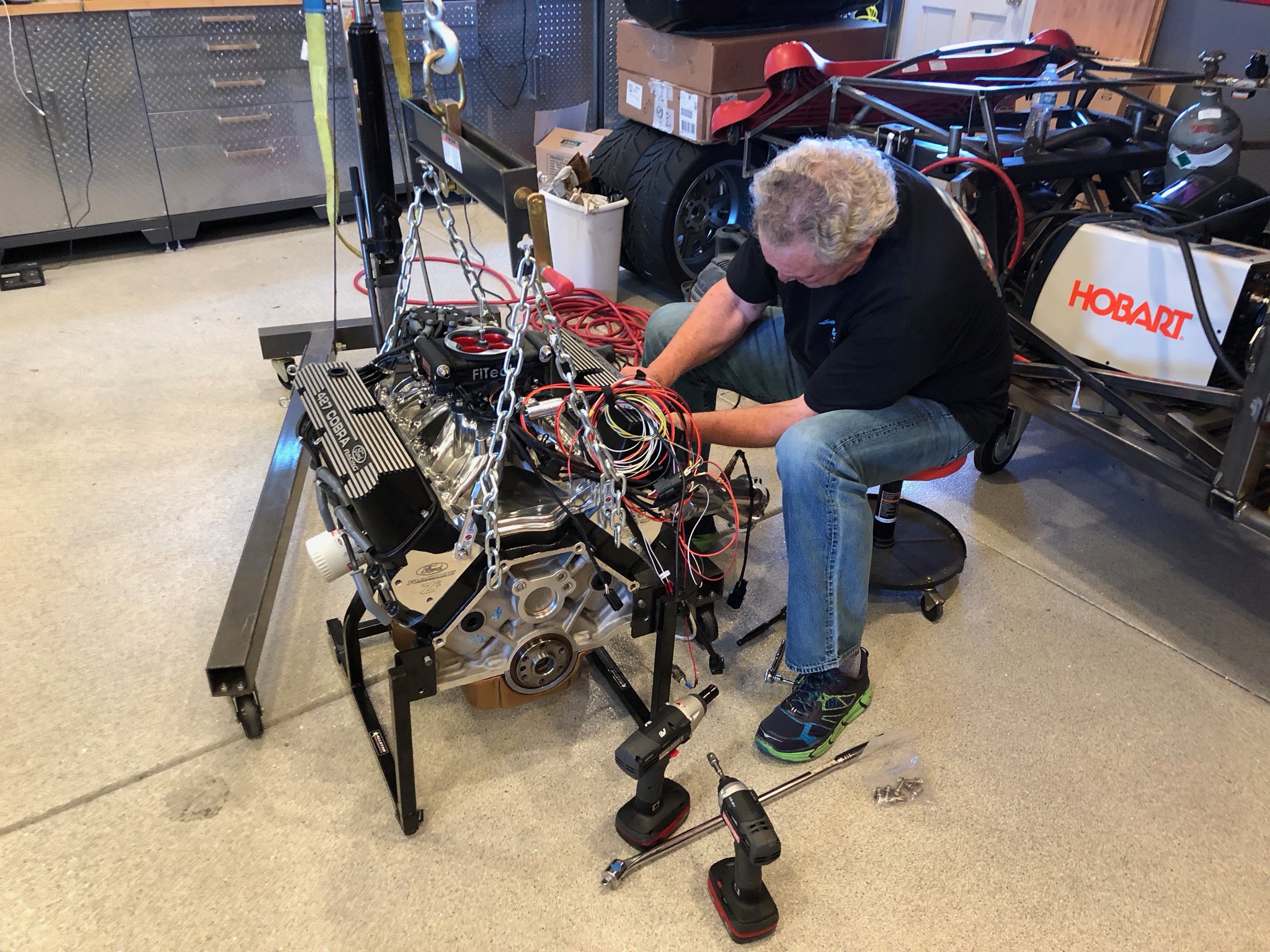
At some point during the dyno run, the vibration caused that nut to back off and get sucked into the engine.

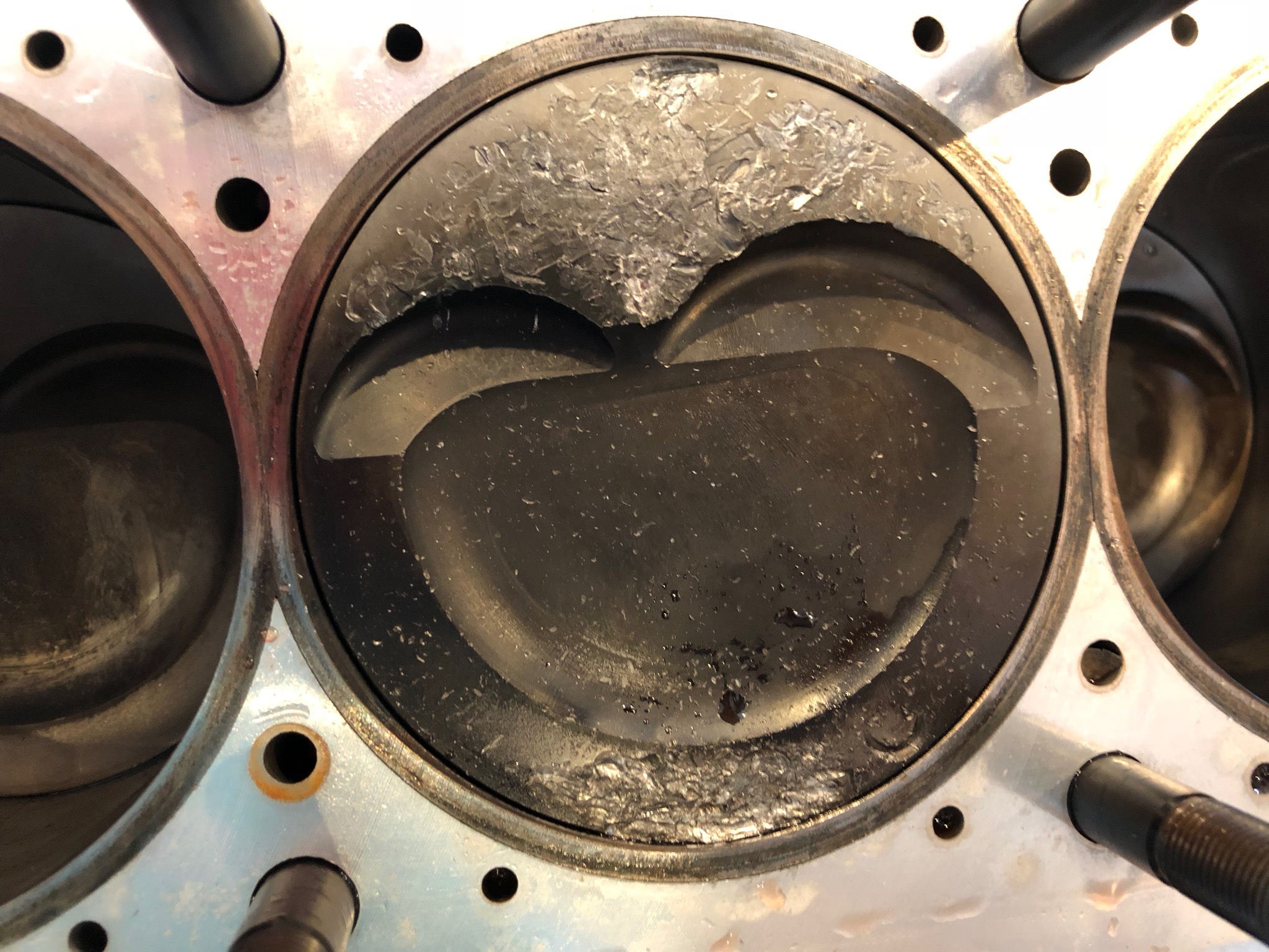
It appears to have spent most of the last moments of its short life bouncing around the inside of cylinder #6. It caused considerable damage to the top of the piston which is what prompted us to pull the heads. While diagnosing the rough running engine, I borescoped all of the cylinders and spotted the damage. Although the nut was long gone, I couldn’t tell that without pulling the heads. My dad stopped by today and we pulled both heads in about 1.5 hours.

The underside of the head was pretty damaged as well.

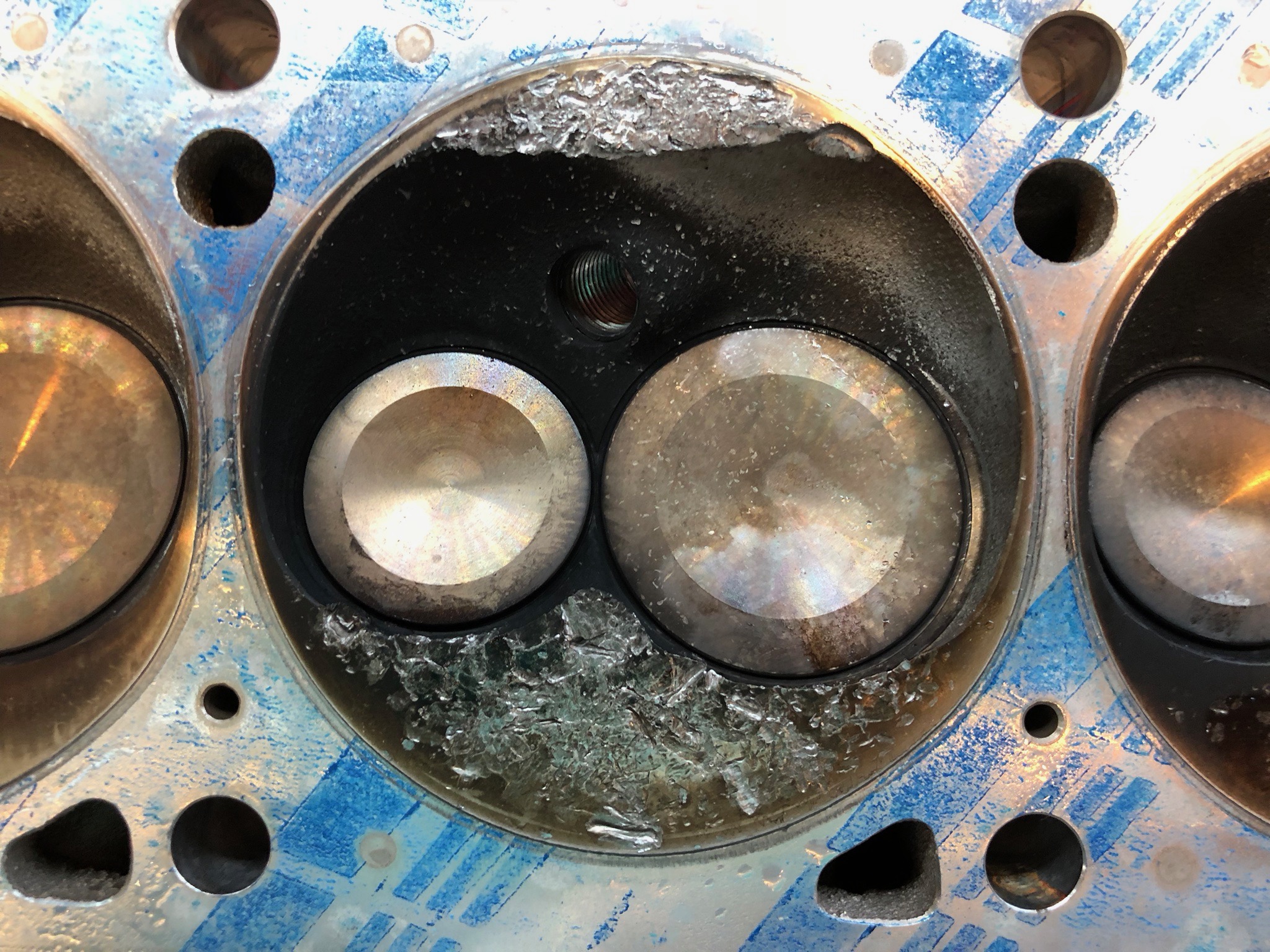
Interestingly, there was minor damage in most of the cylinders, though nowhere near as bad as #6. This is the second worst cylinder and the piston doesn’t look anywhere near this bad (probably because it is forged).

We’re going to get some opinions on this over the next week. It seems likely we’ll need to replace at least one piston and at least resurface one or both heads.

Finished Coolant System and First Engine Start in Car

I cut and installed the two pieces of tubing that connect the radiator to the engine. I’m not sure we’ll stick with this flex tubing, but it will work for now. I also just loosely zip-tied the coolant expansion tank to the chassis. We’ll be replacing this with a larger Canton Racing unit that we’ll order later.

The lower tubing snakes under the x-frame and steering rack before coming over the front sway bar and connecting to the lower left corner of the radiator.

After filling the engine with coolant, I test fired the engine and for some reason it ran surprisingly rough. It ran perfectly on the dyno, and there were only a couple of things we’ve touched since then. One of the concerns we had was that we could have cracked one or more of the spark plugs while removing and replacing the headers. I pulled them all and found them fairly carbon fouled.


Here’s the second one from the left in the photo above (probably the worst of the bunch). We knew that we were probably going to have to adjust the heat range of the spark plugs, but I’m still surprised how fouled these are for the engine being run for no more than 1.5 hours at the dyno shop.

Installed Radiator

I’m using the Breeze Automotive upper and lower radiator mounts which reduce the stress on the radiator flanges which apparently are prone to cracking with the factory mounting method. The factory had you bolt the upper flanges to these welded on pieces of square steel tubing, but they’re not necessary with the Breeze kit. I cut these off and then ground the upper tubing back to the right shape.

The hinge that is riveted to the upper radiator flange is then bolted to the cross bar. Then instructions have you drill and tap the square tubing, but that is pretty thin wall tubing, so I will probably just drill out these holes and use longer bolts with lock nuts.


The lower part of the radiator is supported with a smaller piece of square steel tubing that I’ve just loosely clamped on for now. The instructions specify this should be mounted at 51º, but I want to test fit the side aluminum before locking in the final position of this.

Installed Radiator Mount and Shroud

I ordered an upper and lower radiator mount from Breeze Automotive along with their radiator shroud. I centered the shroud on the aft side of the radiator and drilled three holes along the bottom edge. The bottom edge is only bolted to the aft flange of the radiator.

On the upper end, I drilled and riveted a stainless steel hinge to the forward flange. I then drilled a couple of holes all the way through both flanges of the radiator.

Using a couple of spacers, I clamped the front and back flanges together.

Wrapped Up Engine Prep

I didn’t get any pictures, but I bolted the transmission mount to the transmission with a stack of washers and some 2.5″ x 7/16″-14, grade 8 bolts. I also picked up some 1″ diameter, 6061-T6 aluminum rod to use to make some spacers once I’m sure of the exact dimensions.

I then tightened the engine mount bolts so the engine is hopefully locked in its final position. I won’t really be able to know until the body goes on and I see where it places the side pipes.

Jenn came out and helped me install the left exhaust header. It’s much tighter with the foot box in place, but not too bad.

The header comes pretty close to the rubber on the input side of the electric power steering motor. I’ll probably fabricate a heat shield to reflect radiant heat away from the motor and the rubber piece.

I also cleaned up the old gasket and reinstalled the water neck and thermostat bypass hose.

Finally, I reinstalled the air cleaner and breather cap. Once I hook up the radiator, the engine is ready to run in the car.

Fit Transmission Mount

I jacked up the transmission and slipped the transmission support underneath and placed it on top of the aft chassis support. I loosely bolted the transmission mount to the top of the transmission support, roughly inline with the holes in the bottom of the transmission.

I then lifted the transmission up until it was aligned with the differential flange.

That creates a pretty big gap between the top of the transmission mount and the bottom of the transmission. I’ll need to fabricate some spacers that fit here.

Before measuring for the spacers, I wanted to make sure that the engine is level in the chassis. I measured the angle of the chassis and then adjusted the engine until it matched. I then measured for the transmission spacers. For some reason, even though the engine is level, the spacers are about 0.200″ different in height. I may just use some washers for now until we get closer to the end of the build and know the engine doesn’t have to be adjusted further.

Further Engine Prep

I spoke with Tony at Factory Five today about the driveshaft issue. He suggested that the engine mounts could be installed backward, but I tried flipping them and I can’t see how they could be installed on the wrong sides. I took these pictures to send to him to confirm though. Here’s the right side.

And here’s the left side.

Since I’m not using a mechanical speedometer, I installed a plug in the hole at the left, rear side of the transmission.

I also removed the upper transmission fill port plug and added the transmission fluid until it started coming out the hole.

Finally, I replaced the crappy hose clamps in the hoses to and from the PCV valve with these much nicer ones.

Prepped Engine to Run

We have a Halloween Party at our house every year, and it’s coming up in less than two weeks. I decided it would be fun to be able to fire up the engine at the party because I’m sure many people will be interested in the party. To that end, I’m going to hook everything back up as it was at the dyno shop along with the necessary additional bits to run the engine in the car (cooling system, starter, oil pressure and coolant temperature gauges, tachometer, etc.).

The dyno shop removed my oil pressure sender and hooked up their own hose to this extension. I reinstalled the sender and then hooked up a temporary pair of wires to drive the oil pressure gauge.

The dyno shop also installed their own coolant temperature sender, so I reinstalled my sender and hooked up the wires.

I also hooked up the engine ground strap from the right front engine mount bolts to the hole already provided in the mounting bracket.

To be able to start the car, I used some scrap aluminum to temporarily hold the ignition switch. I still need to wire this, but there are only a few connections to make.

I don’t want to start the car unless I can monitor oil pressure at a minimum, but it’s minimal extra work to also hook up the coolant temperature gauge and tachometer. I had considered fabricating a larger aluminum plate to temporarily mount the gauges, but the cardboard box they came in will work just fine.

I also set the fuel tank on top of the rear part of the chassis and hooked up the fuel lines. This has 4-5 gallons of fuel in it right now, so it’s fairly heavy. I’ll probably end up burning off a good chunk of this doing some demo and tuning runs. I need to get this lighter before I start messing with mounting this in the rear of the chassis.

Installed Engine in Car

Jenn and I installed the engine in the car. With two people, this is pretty trivial. We lifted the engine until we could pull the chassis underneath it.

We then tipped the engine so that the transmission would drop into the tunnel and then lowered and releveled the engine/transmission.

We used a floor jack to lift the transmission and keep it above the 4″ cross tube.

We then lowered the engine onto the mounts and installed the bolts.

Unfortunately, the driveshaft it too long. I slipped the driveshaft as far forward as I can (until the seal just touched).

But you can see that there is no way to slide the driveshaft into place. We’re at least 1/2″ too long and even that would probably cause the seal to rub on the front of the u-joint instead of the outside of the splined shaft. I’ve sent an email to FFR to see how to resolve this.

With the engine in place, I installed the headers on the right side of the engine.

The left side will be a little more challenging since the foot box is in place. We did verify that the header will slip into place, but it’s ridiculously tight. I was hoping to enlarge the foot boxes, but I don’t think there is any room to spare.

Wrapped up Dyno Visit and Prepped Engine for Install

We went back to the dyno shop this morning to wrap up the dyno pulls. After doing some research last night, I was concerned that the distributor base timing wasn’t accurate. We warmed up the engine and then hooked up a timing light. Sure enough, we were advanced more than the 12º of base timing that I was shooting for. That explains why the engine ran poorly when we advanced total timing to around 32º yesterday; we were really around 35º or 36º of advance.

The first pull we did after resetting the base timing was over 500 lbf-ft of torque and over 500 hp. We did a second run without changing any settings and the numbers improved a bit more due to the ECU learning the optimal settings. We advanced the total timing to 32º again and it didn’t make any more power, but we did run a little worse. We dropped the total advance to 30º and got the best pull of the day at 516 lbf-ft of torque and 516 hp! We could probably push it further, but we’re more than happy with these numbers and the engine runs beautifully.

There are a couple of interesting observations about this graph. First, the torque curve is amazingly flat and broad. We’re over 450 lbf-ft of torque from 2800 rpm to 6000 rpm. Second, the horsepower was still rising at 6000 rpm. Although the curve was flattening out, I’m sure the power is a little higher over 6000 rpm. We’re going to set our redline at 6500 rpm, and I’m sure the power is falling by that point.

With the dyno runs complete, we brought the engine home and began prepping it for installation in the car. My dad stopped by and we pulled the exhaust headers since they’re too wide to drop into the car. While he was doing that, I pulled the flywheel and cleaned it thoroughly.

After pulling the engine off of the stand, we installed the bell housing separator plate and reinstalled the flywheel. After installing the pilot bearing and the pressure plate indexing dowels, we installed the clutch and pressure plate. We ended up setting the clutch fork pivot bolt so that there is about 1/8″ of clearance between the the front side of the pivot point on the fork and the back side of the pressure plate. This positions the fork so that it is sticking almost exactly straight out the side of the bell housing.

With the bell housing in place, we mounted the starter to the forward side. We had previously test fit it to the separator plate without the bell housing to ensure various install tolerances were met. After this, we installed the transmission which slipped into place surprisingly easily.

The push rod on the clutch slave cylinder is longer than will work, so I cut down the bearing end as well as the other end.

With that reinstalled in the slave cylinder and a couple of extra washers spacing the mounting bracket aft, everything fits perfectly.

The engine is ready to drop into the car. We’ll tackle that tomorrow when Jenn is free since she wants to help with this step.