Finished Installing Pro 5.0 Mid-Shift Kit

I stopped by Harbor Freight and picked up a set of punches. I bent the 3/16″ punch a bit until I could use it to drive out the roll pin in the forward lug of the aft shaft.

You can see that I started driving the pin out from the left side. This was a mistake as the pin hit the case before it could be driven out completely. This wedged the shaft so that it couldn’t be rotated or slid forward/backward. After scratching my head for a few minutes, I decided to try and bend the pin to make more room to drive it out. I hit the side of the pin with a punch and bent it enough to move the pin a little more.

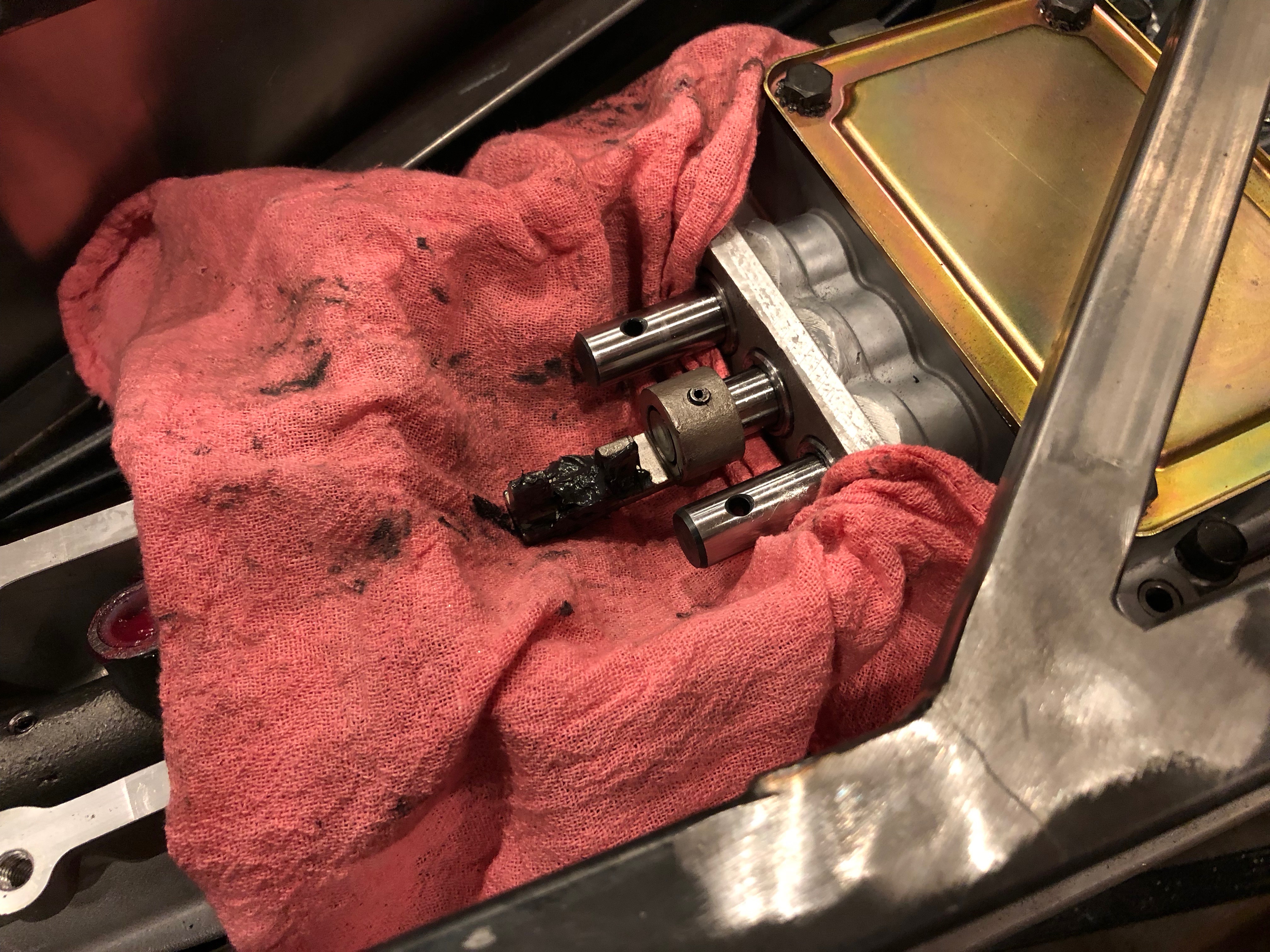
After a few rounds of bending the pin and driving it further out, I managed to free the lug from the aft shaft.

Here’s how the pin was mangled in the process.

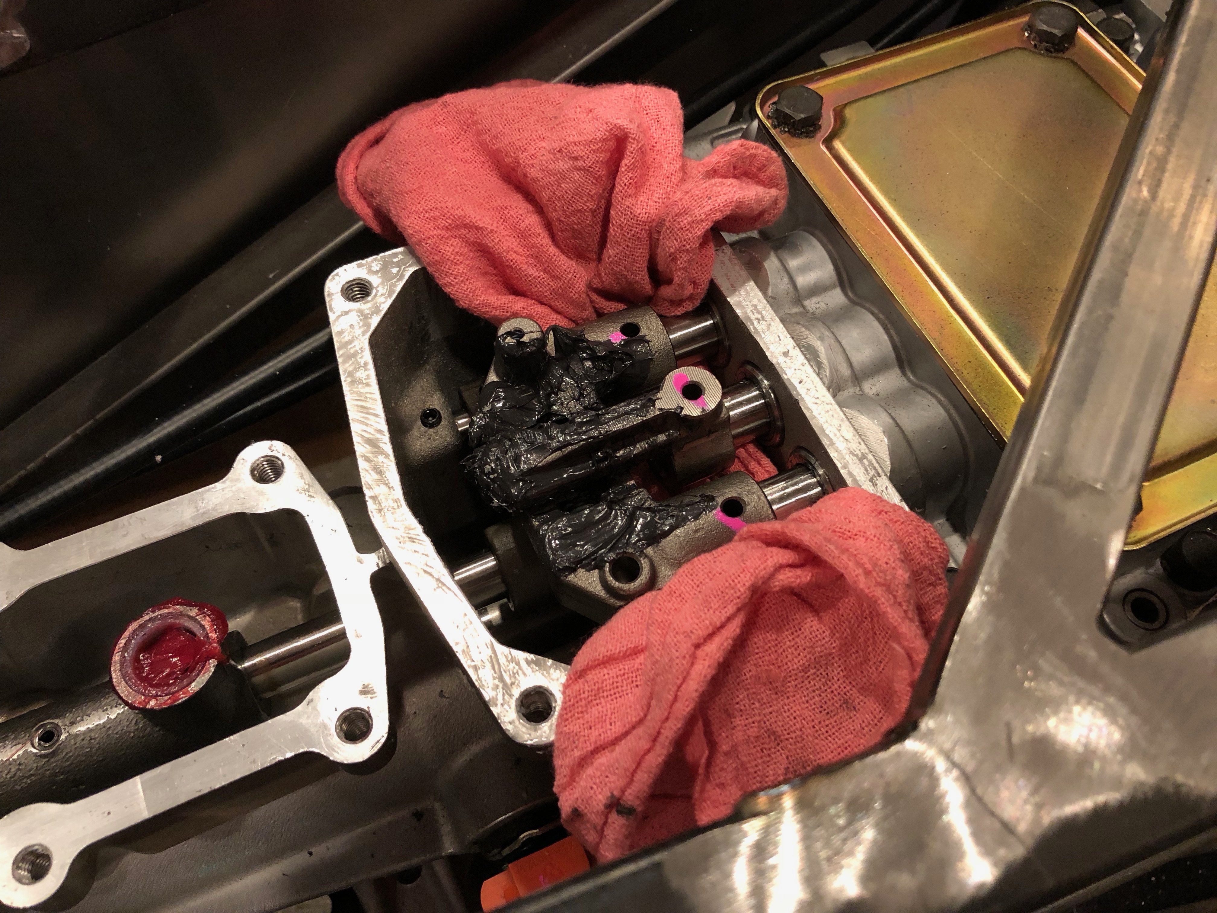
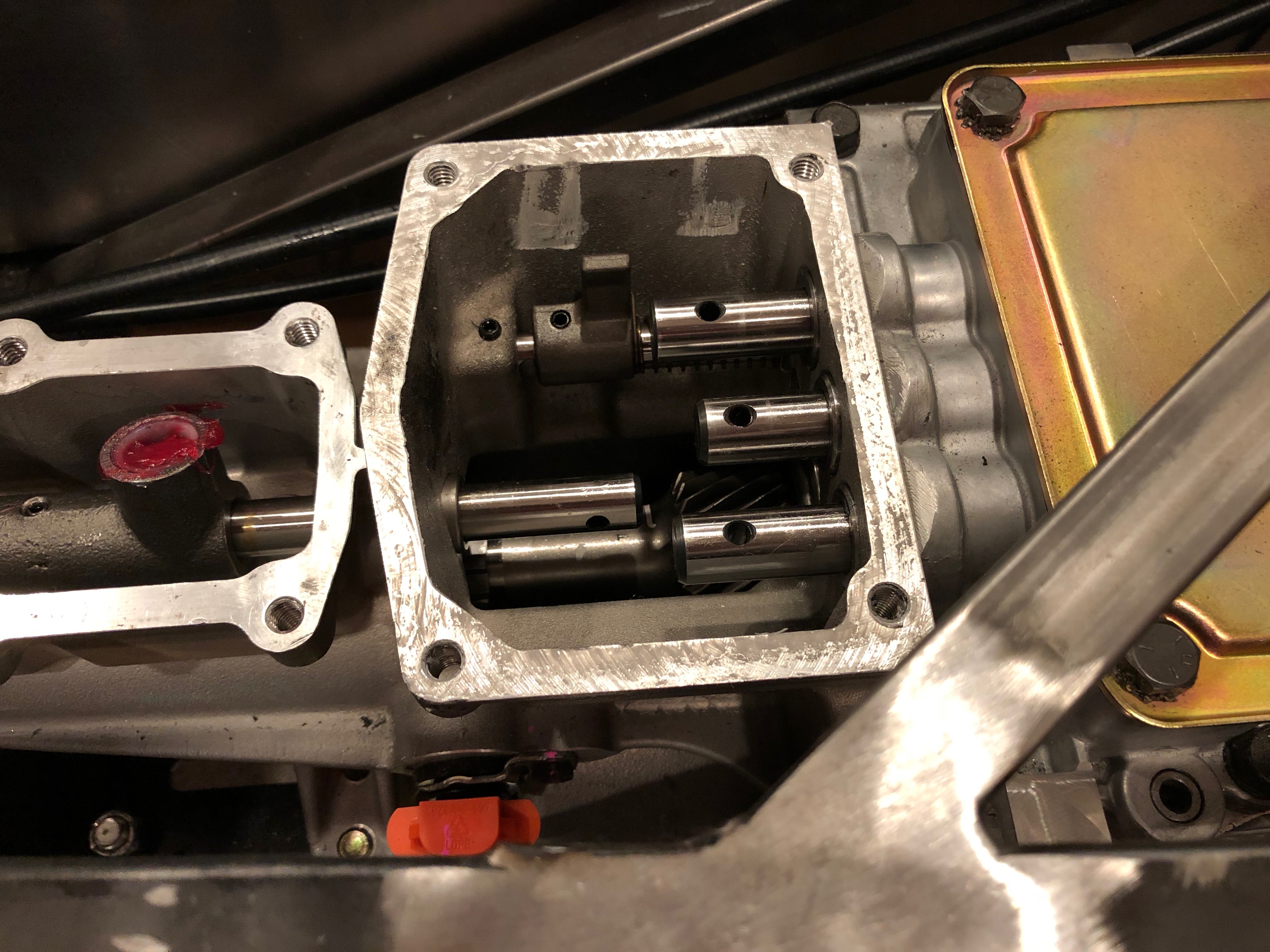
I put a rag back under the forward shafts in case I dropped a roll pin, and then began reinstalling the shift lugs. First up is the new center lug on the 3/4 shaft, this time installed upside down so that it can be driven from above.

I then reinstalled the outer lugs on the 1/2 shaft (bottom) and 5/R shaft (top).

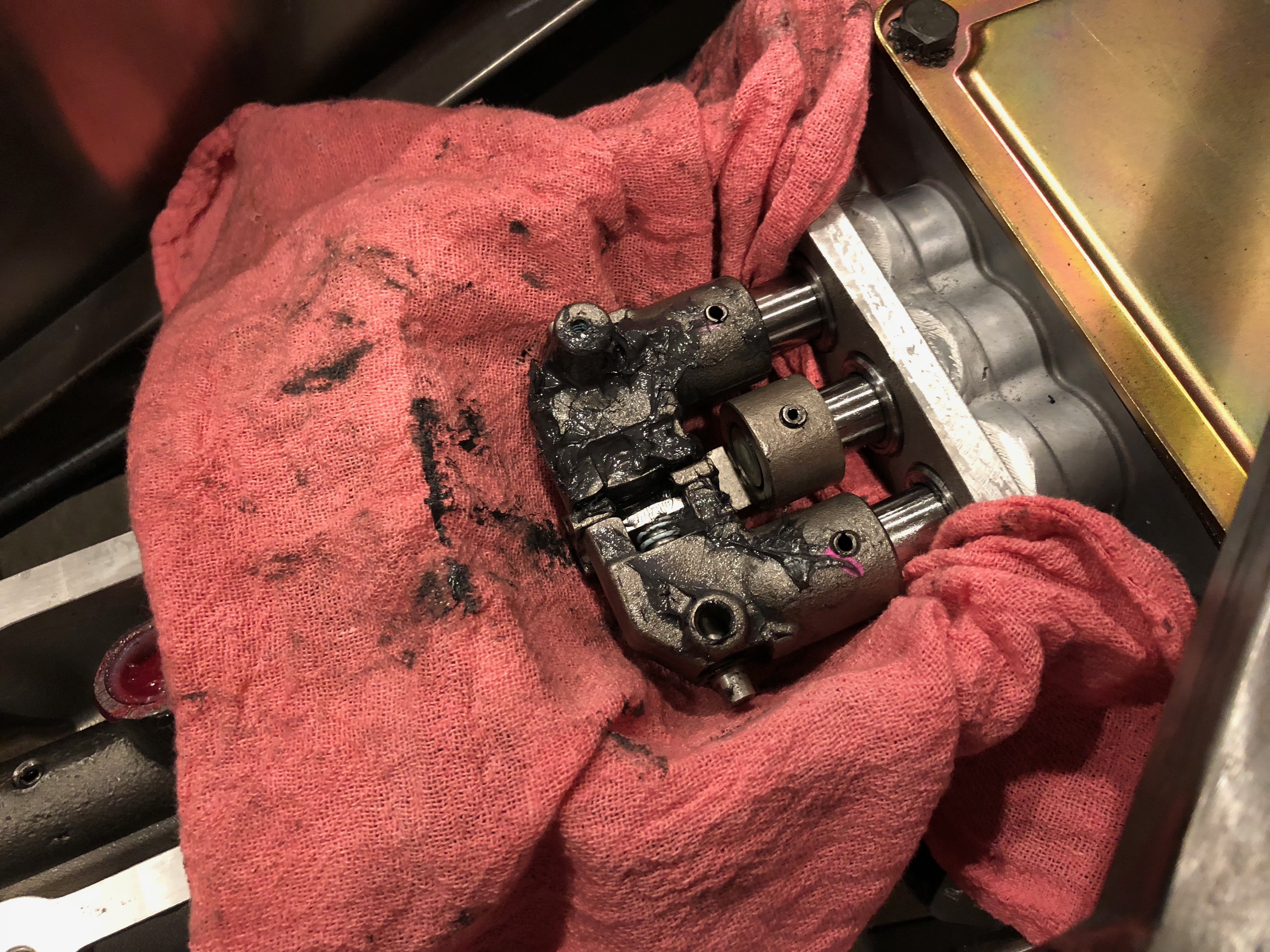
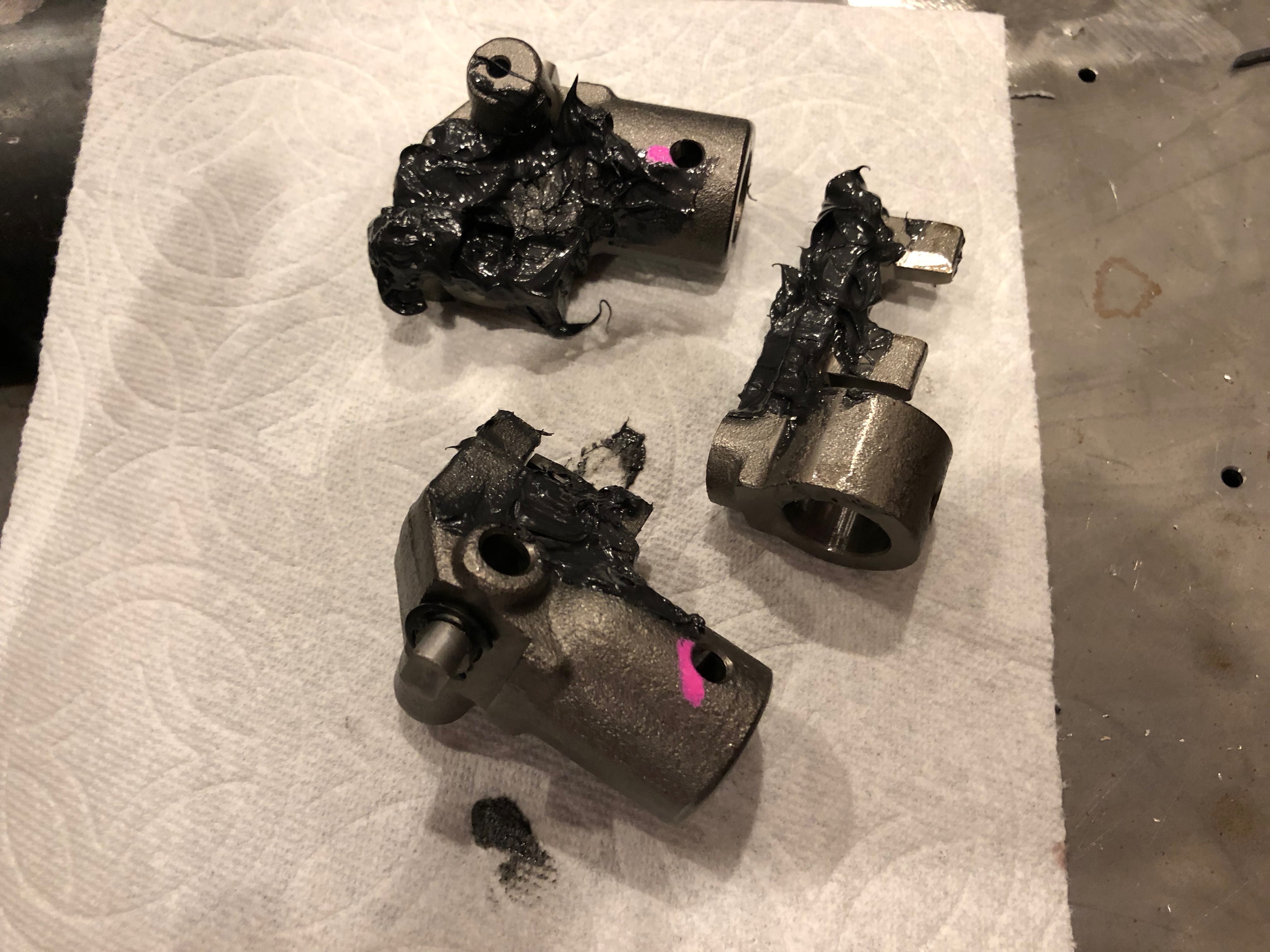
I packed the intersection with moly grease.

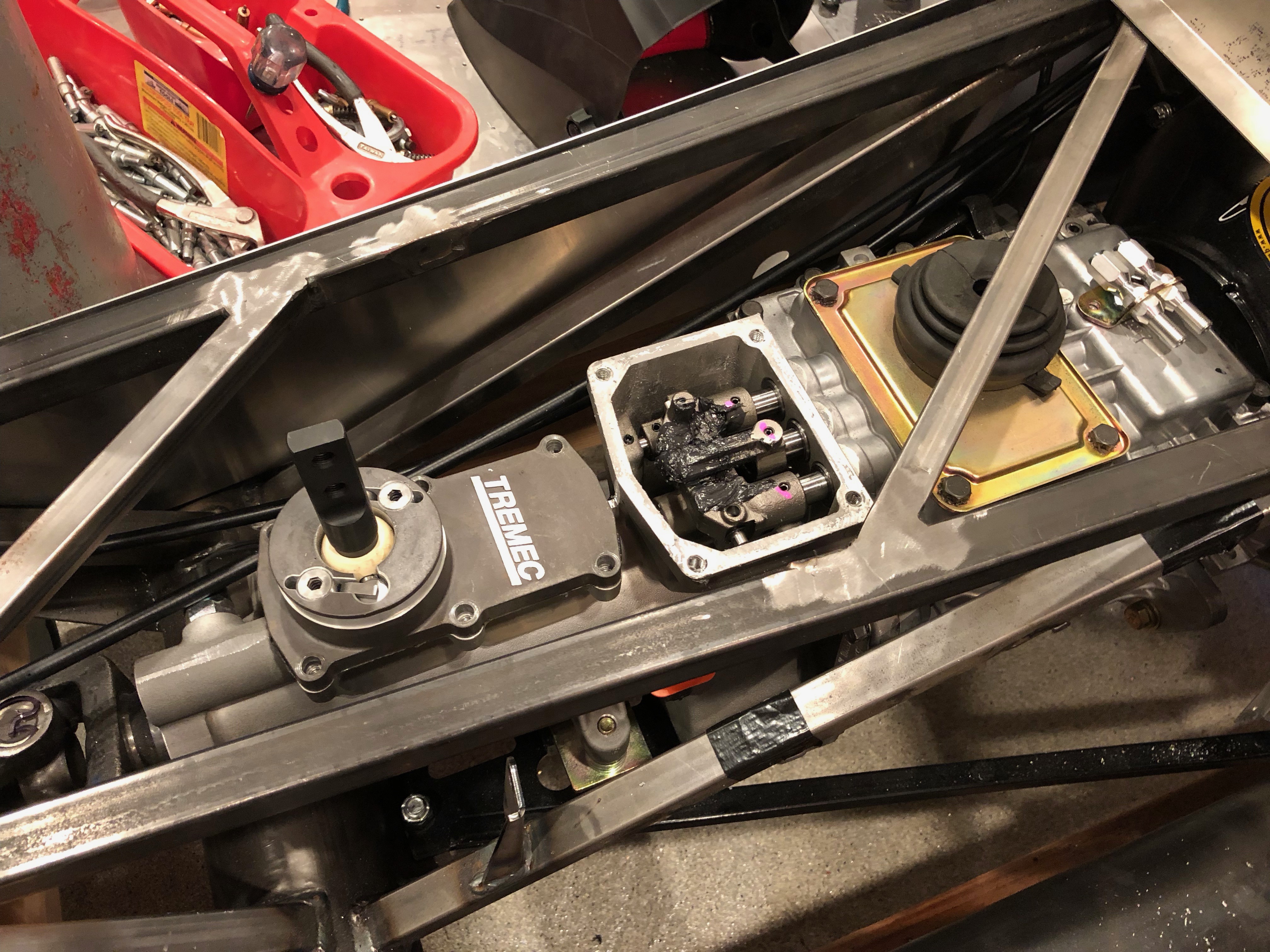
I applied some black RTV to the flange and installed the cover over the aft cavity.

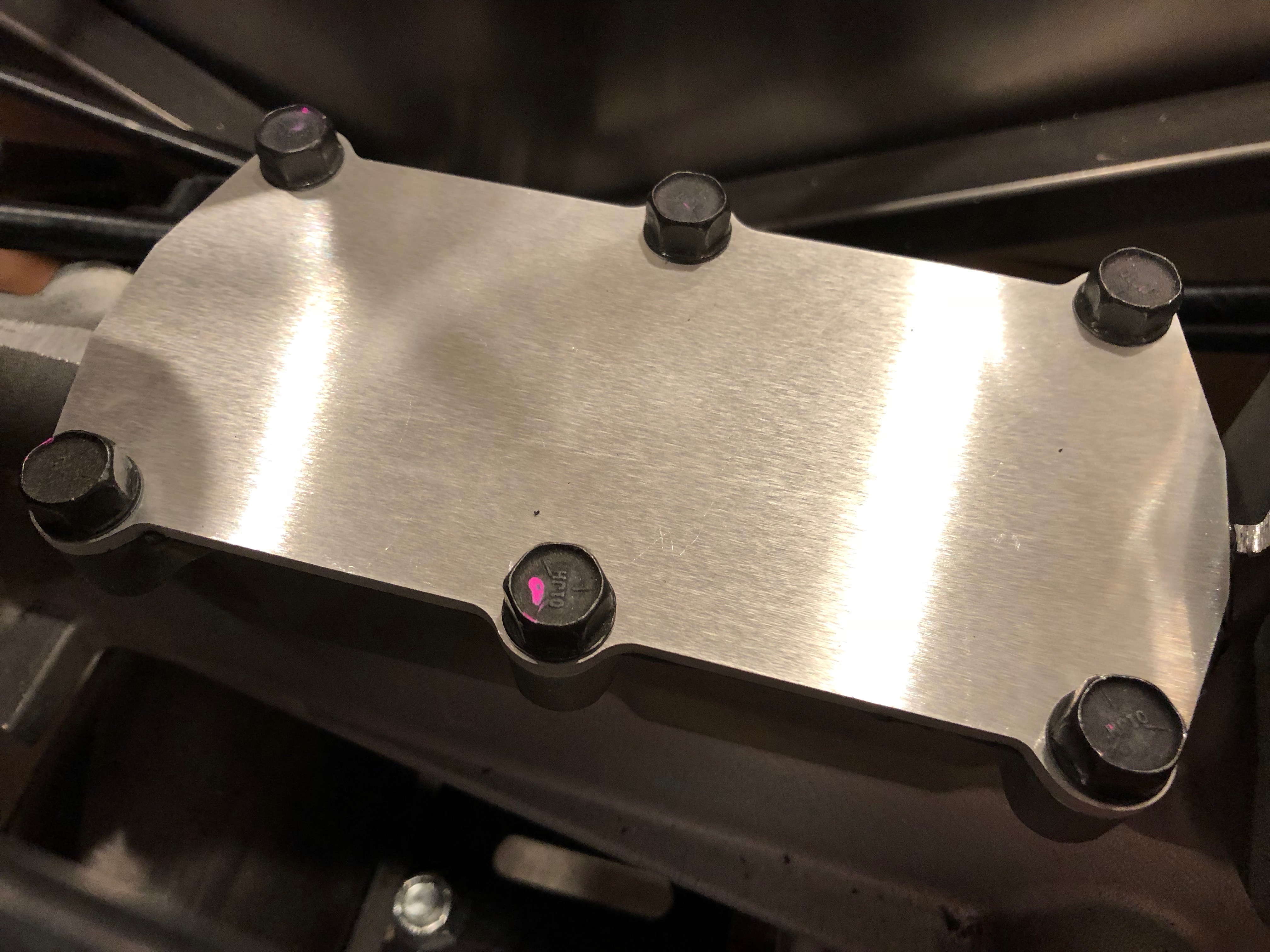
I then applied some black RTV on the flange of the forward cavity and installed the cover plate. Finally, I applied another thin layer of RTV and installed the shifter. All of the bolts were torqued to 20 lbf-ft.

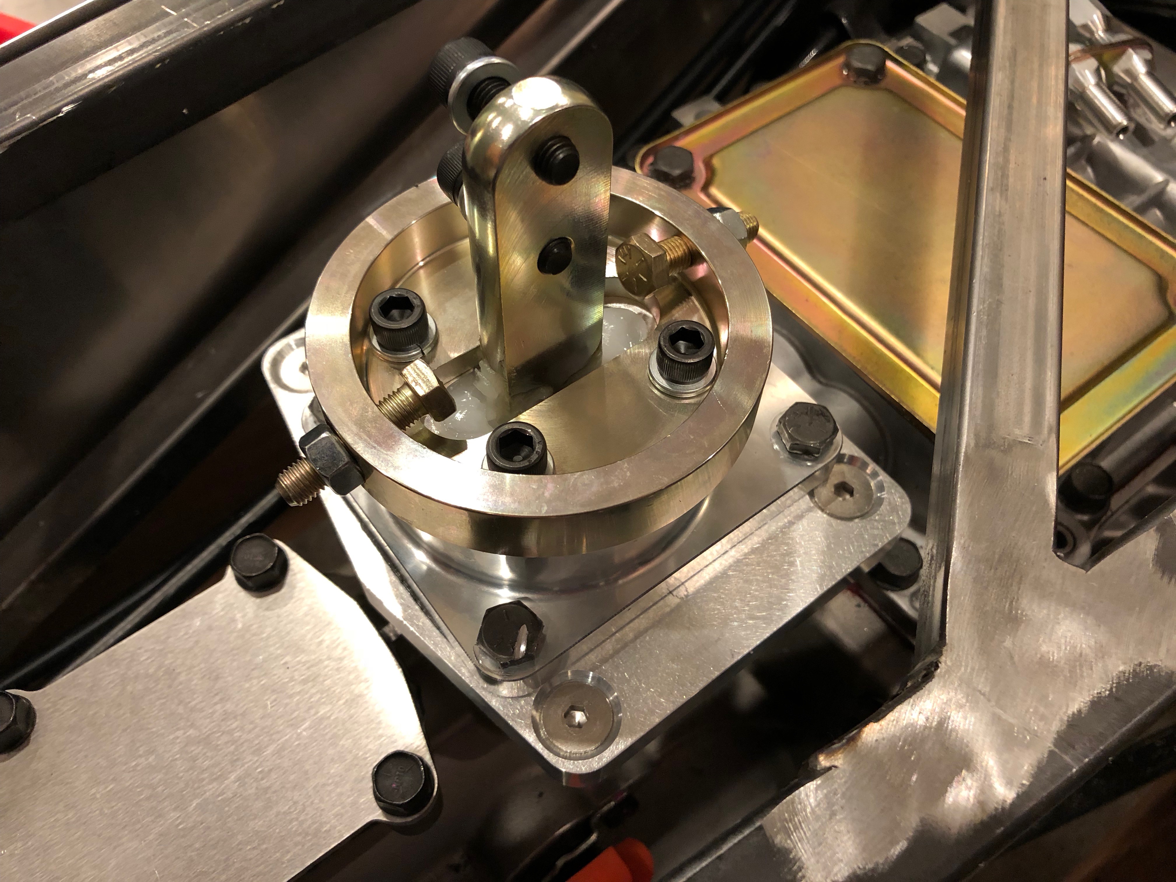
The shifter came with a rubber cover to keep dust out of the mechanism. I’ll have to remove this (or at least pull if back) to adjust the mechanical stops, but I need to wait until I have a shift lever installed.

Started Installing Pro 5.0 Mid-Shift Kit

Jenn really wants to move the shifter forward and have a more vertical shift lever for a more traditional feel. We picked up the mid-shift kit from Mike Forte that includes a Pro 5.0 shifter and appropriate mounting plates and hardware. First up is to remove the bolts and forward cover plate. The RTV they used around the edge of the cover plate held it on tenaciously and was a pain to clean off of the flange after removing the cover plate.

The instructions from Tremec have you knock out the roll pins holding the three shift lugs and just let them fall to the bottom of the aft case. It’s pretty trivial to fish a rag under the lugs to catch the roll pins though.

After removing all three roll pins, the lugs can be slid off the shafts pretty easily.

Here are the three lugs. The kit from Mike includes a replacement center lug, but it looks identical to the one I removed.

The new center lug is installed upside down so that the opening is facing up, but it can’t be installed until the forward lug on the aft shaft is remove (the one on the right in the picture). Without removing the shaft, it’s a bit of a pain to remove the lug because you can’t get a punch directly aligned with the roll pin. I managed to drive it part way out, but I’ll need to fabricate a slightly angled punch to drive it the rest of the way out.

The reason that Tremec doesn’t care if the roll pins fall to the bottom of the case is that they want you to separate the front and back cases to entirely remove this aft shaft, and it’s pretty easy to retrieve the roll pins if the aft case is removed. That’s not strictly necessary though; once the forward lug is removed, the aft shaft can just float and won’t interfere with the shift lugs. The weight penalty is negligible, and it’s way less work to leave the case halves mated.

Coolant System Work

I received an order from Summit Racing with my new coolant overflow tank. Given the volume of coolant in the engine, the consensus on the forums is that the coolant reservoir tank that comes with the kit is too small. This tank from Canton Racing is over twice the volume at 2 qts. It’s also a beautiful piece of work.

I have been thinking about mounting the reservoir inside the right F-panel. This should clear the upper radiator tube, but I’m concerned that it will interfere with the hood hinge and support strut.

To see whether that is true, I assembled the hood hinges.

These attach to the brackets welded to the chassis just behind the upper radiator support.

I installed one of the support struts to get a sense of how far back it extends (though it will obviously be compressed when the hood is down). From what I can tell, the aft end of the strut will be roughly level with the upper square tubing.

I might be able to install the reservoir inside the right F-panel underneath the support strut, but I’m concerned that the strut will push the reservoir too low. Another option is to mount it behind the radiator. I should be able to get it high enough here, but I’ll have to fabricate a rather complex mounting bracket.

Now that I know that the upper radiator tube will clear the reservoir in either mounting position, I decided to go ahead and install it.

The tube was slightly too long to fit and there is a slight bend at each end. I cut a bevel to create a small gap at the aft end.

The forward end also needed a slight bevel to create the necessary gap between the tubing and the radiator.

Finally, I installed the upper tube in place and secured the clamps.

I used some T-bolt clamps to secure the rubber connecting hoses in place. These are so much better than the worm clamps that I was using.

Here’s a shot of the whole vehicle. When you look at it like this, it doesn’t look like there has been much progress in the last few months, but there are a lot of details that are lost at this scale.

Installed New Driveshaft

I received the new shorter driveshaft from FFR today. This one is 3/4″ shorter than the old one, so it should fit fine.

I had to loosen the engine mount bolds and remove the lower transmission mounting bolts in order to shift the transmission to the left enough to slide the slip yoke over the transmission output shaft. I then slid the aft flange in place and installed the bolts. Given the mechanical advantage of the diff, I couldn’t hold the rear wheel in place firmly enough to torque these bolts, so I put the transmission in gear to prevent the driveshaft from rotating.

The driveshaft is just short enough that the seal rubs on the slip joint instead of the face of the u-joint.

Initial Idle Adjustment

I turned the idle adjustment screw in a half turn and fired up the engine. It was still idling fairly low, so I continued turning it in until it was idling around 1500 rpm and let it warm up. After it was warm, I started turning the idle down until the Idle Air Control (IAC) was between 3-10. Unfortunately, I blew the lower radiator hose out of the rubber tubing connecting it to the radiator and dumped the coolant. I really dislike the corrugated hose from FFR; I’m going to replace it with some rigid tubing from Breeze Automotive.

Finished Reassembling Engine

I finished reassembling the engine and then did an oil change, refilled the coolant system and installed new spark plugs. Jenn did the honors and the engine fired up immediately. The idle still isn’t set right, so you needed to hold the throttle open slightly to keep it running. It was getting late, so we shut it off for the night.

Started Engine Reassembly

Jenn and I started the engine reassembly tonight. We started by thoroughly cleaning the heads and deck and then torquing them down. After reinstalling the pushrods, and rocker arms, I installed the intake manifold gaskets with some gasket sealant to hold it in place while installing the intake manifold.

After applying some RTV to the china walls, I installed the intake manifold, throttle body, water neck and rocker arm covers. We should be able to fire up the engine this weekend.

Prepped Cylinder Heads

My dad dropped off the cylinder heads today. Fortunately, resurfacing them did remove most of the damage. I removed the valves and cleaned up some more to make sure there were no protruding bits of metal.

I also inspected the valve seats carefully to make sure there was no damage. Fortunately, they were spotless.

I cleaned up the valves and inspected them as well. The mating surfaces looked perfect, so I reinstalled the valves in the head.

Finally, I cleaned all the RTV off the heads and then trimmed the new head gaskets to match the old ones.

Prepped Piston and Intake Manifold

I masked around the damaged piston and then used a scotchbrite disk on my die grinder to clean up the high spots. There are now no sharp points that could get too hot and cause preignition.

Afterward, I cleaned all of the RTV off of the intake manifold. That stuff sticks surprisingly well. I cleaned most of it off with a razor blade and then used a brass brush to clean off the remaining bits. I’ll use some solvent to get this spotless before reassembling the engine.

Cylinder Head Resurfacing

My dad took the heads down to the guy who did our dyno runs so he could take a look at them and the pictures of our piston damage. He didn’t seem too concerned and recommended we resurface the heads and clean the high spots off the the piston.

He put the heads on the resurfacer and used a dial indicator to check for flatness.


They were off about 0.0015″ across the whole surface, so he reset the surfacer only to mill off the high spots. This removed about 90% of the damage from the heads. I’ll post a picture when I get them back.