First Engine Start


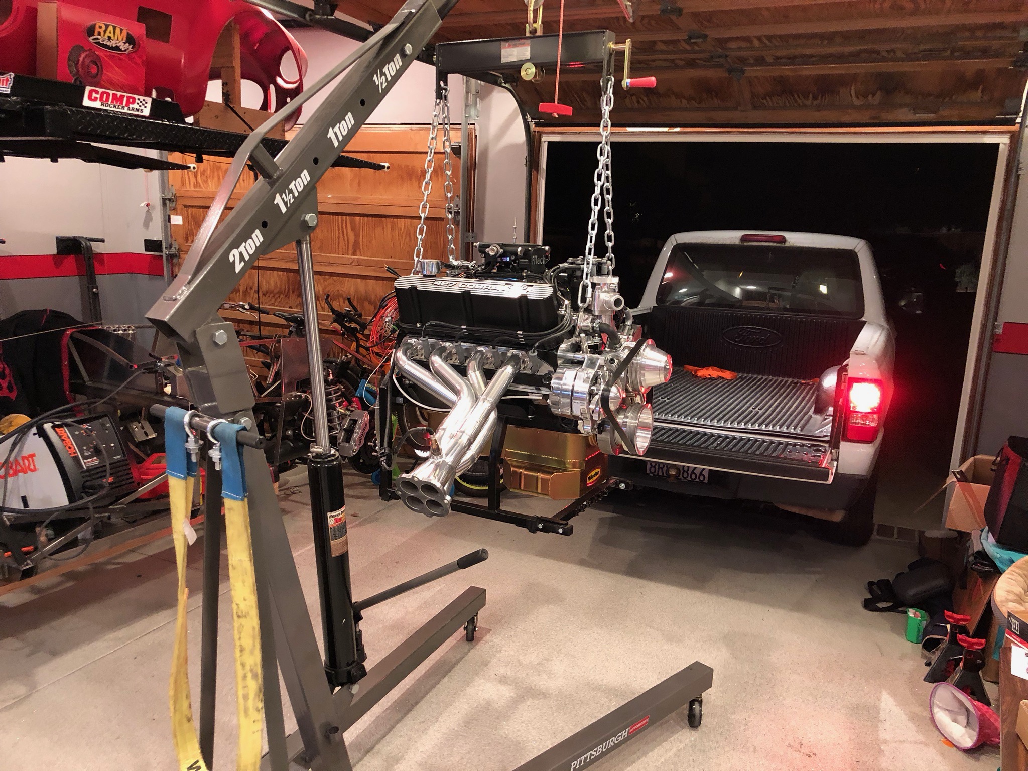
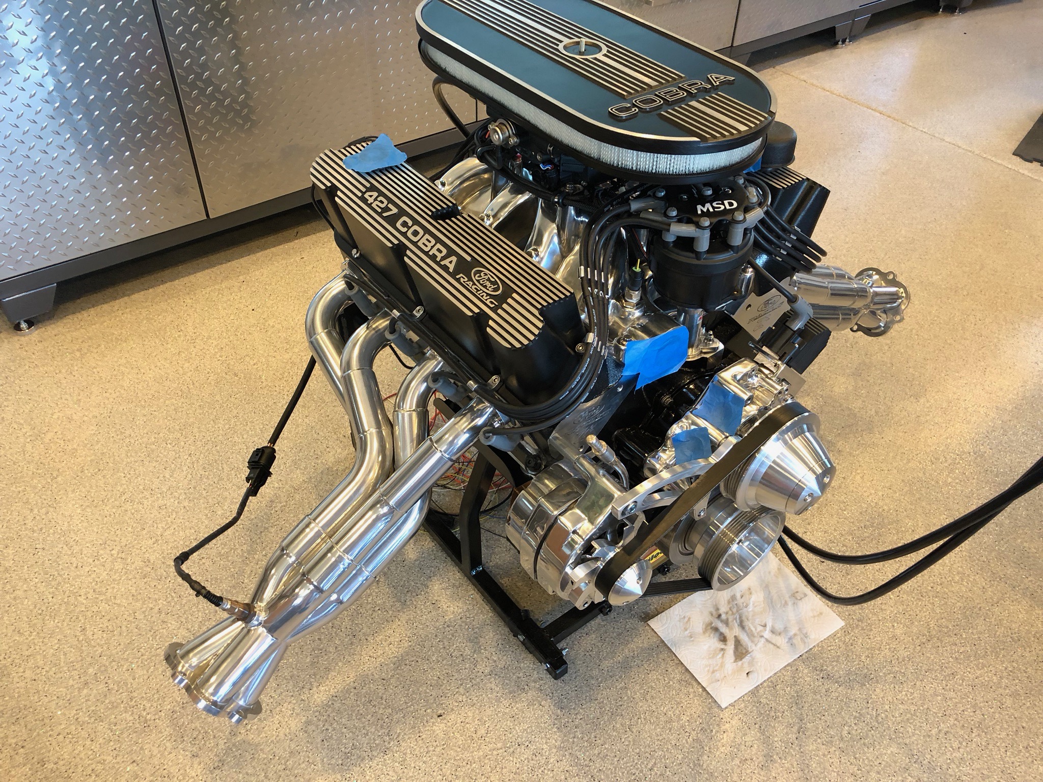
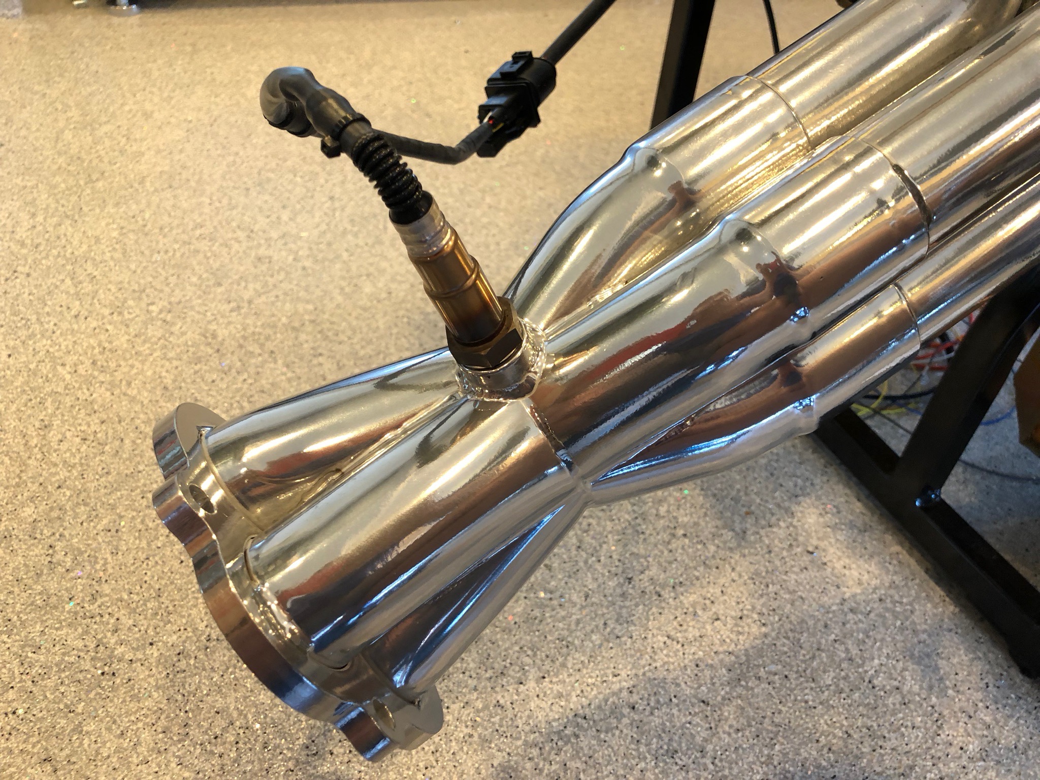
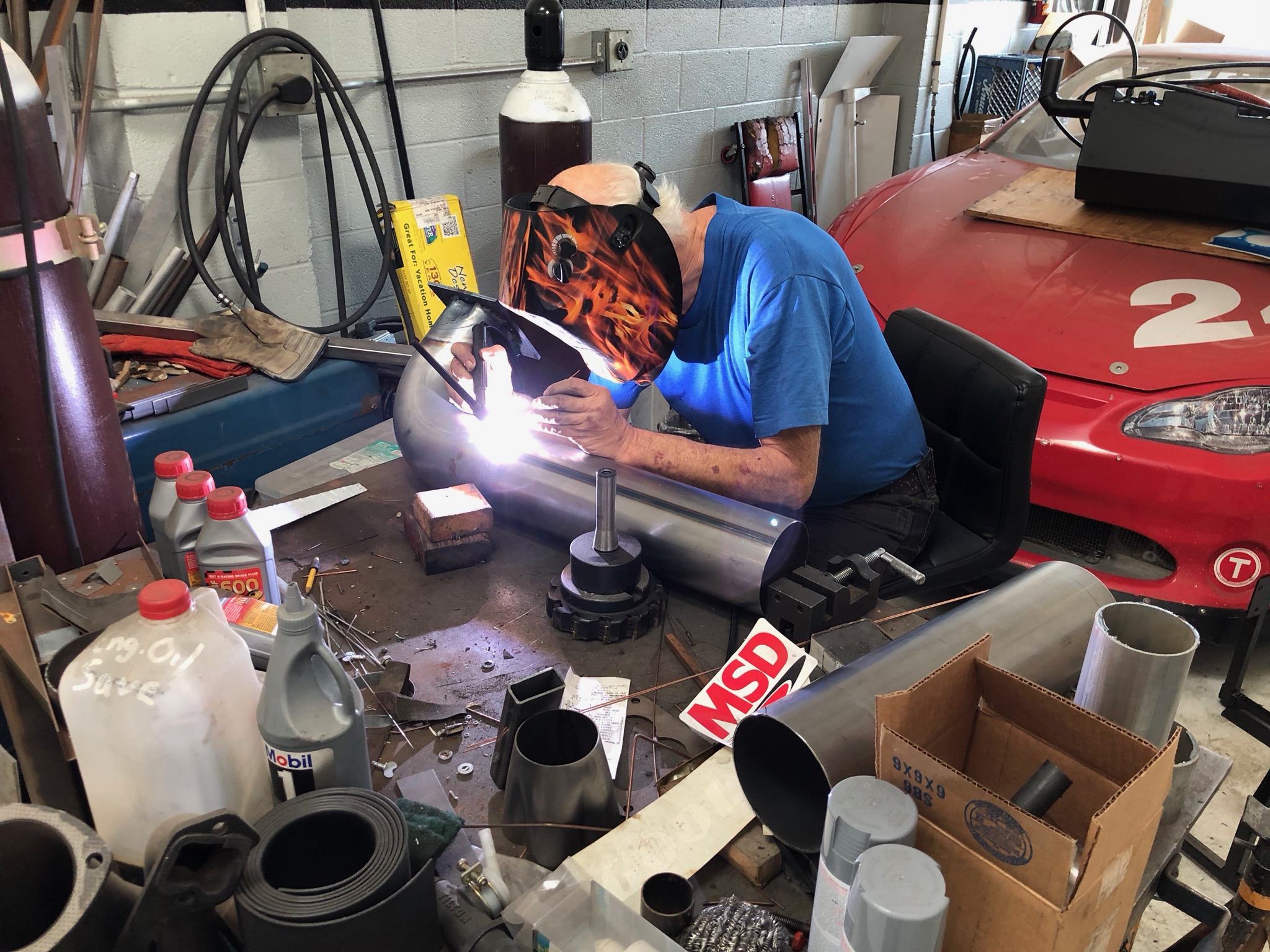
I met my dad down at Dino Fry’s racing shop this morning. Almost immediately, he suggested canceling the dyno run because he had no way to connect his exhaust tubes (the flexible stainless tubing at the bottom left of this picture) to my headers. He suggested ordering a couple of the end flanges from the exhaust manufacturer and welding some 90º elbows onto them to turn the exhaust aft. That could take weeks, so I began suggesting alternatives. He ended up agreeing to weld on the tubing if we purchased it and I could fabricate some exhaust flanges.

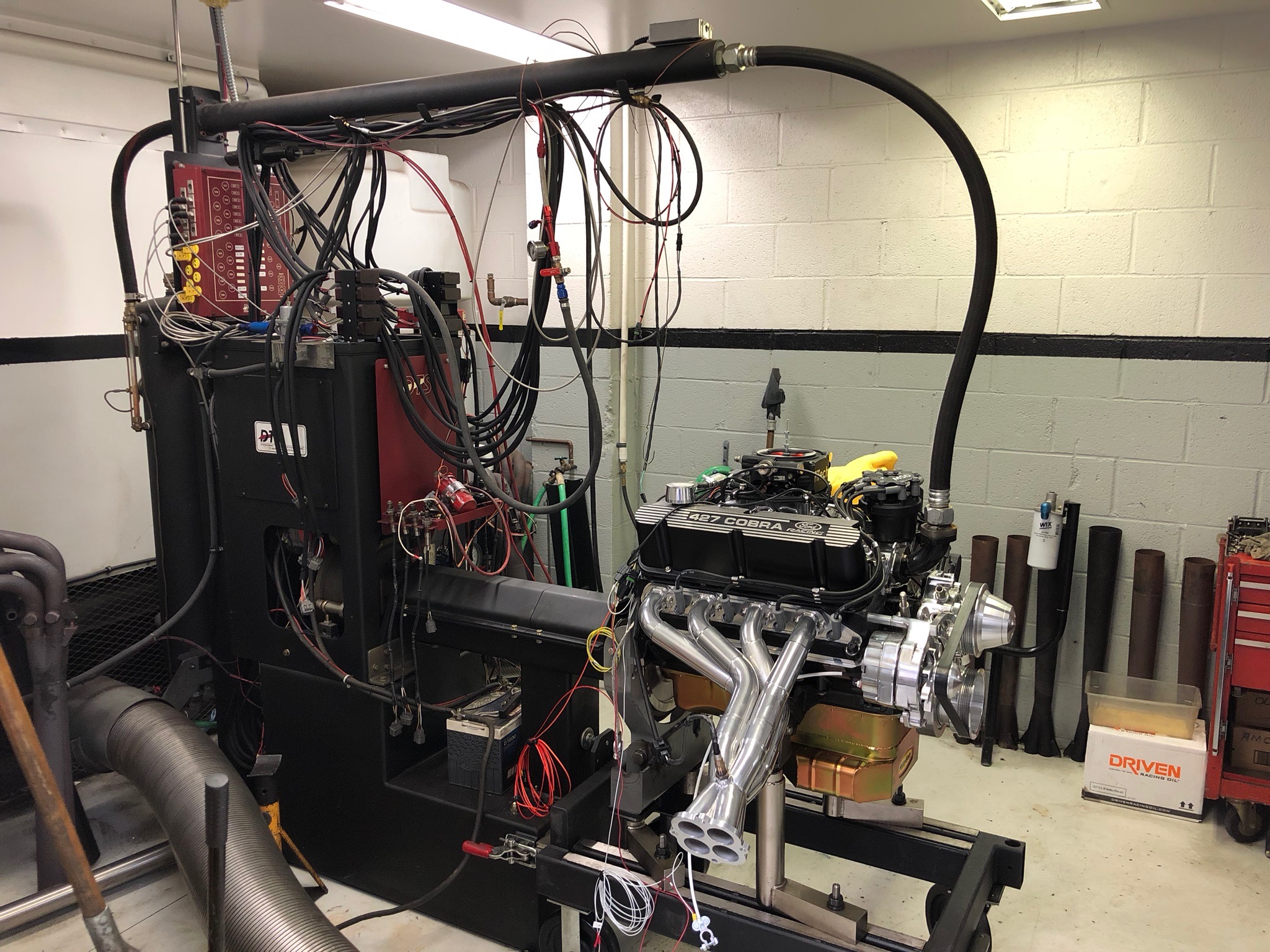
My dad headed over to a diesel semi exhaust shop that had the right tubing in stock and I headed to the TechShop to fabricate the flanges. While we were gone, Dino installed the engine on the dyno.

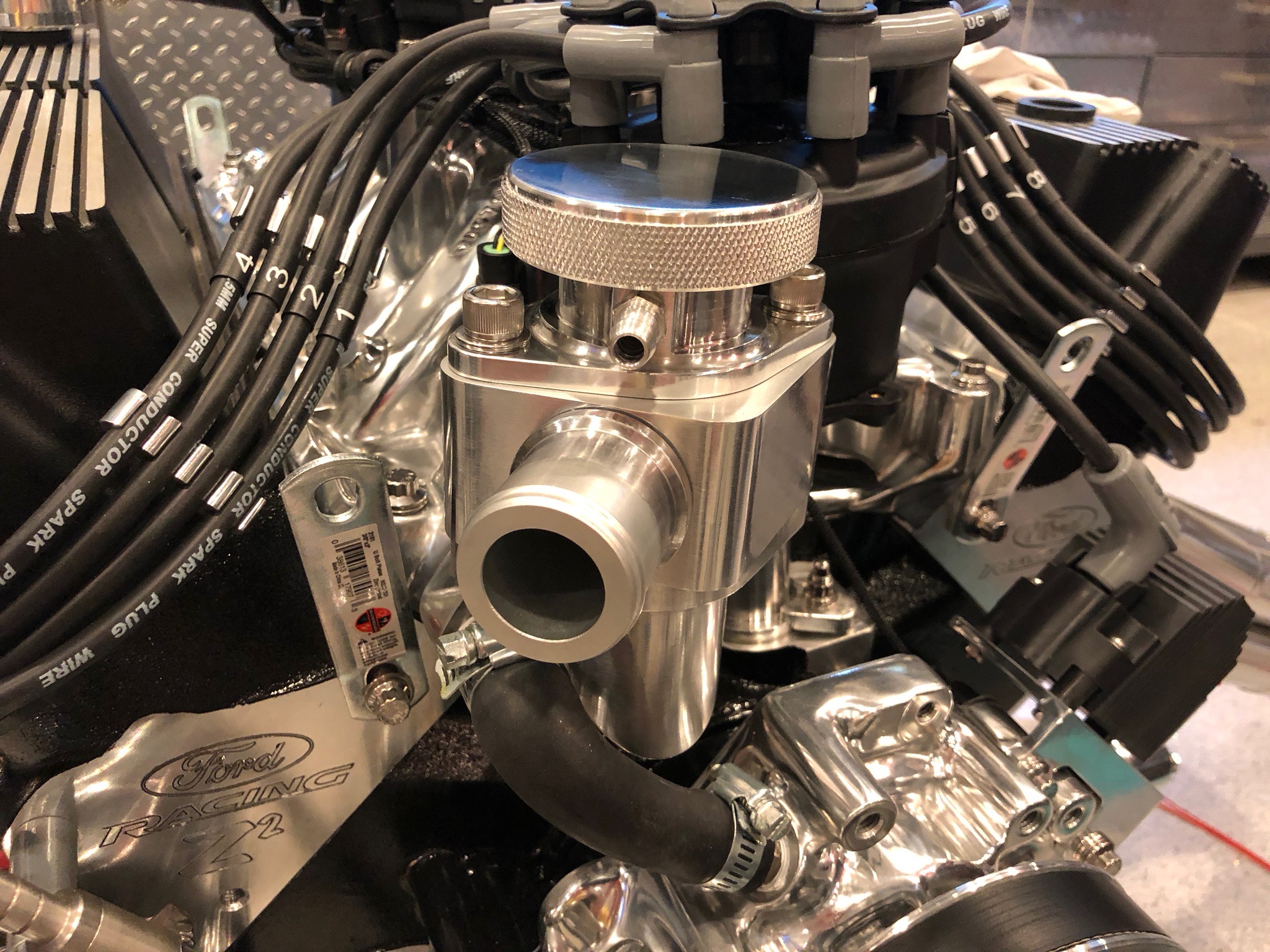
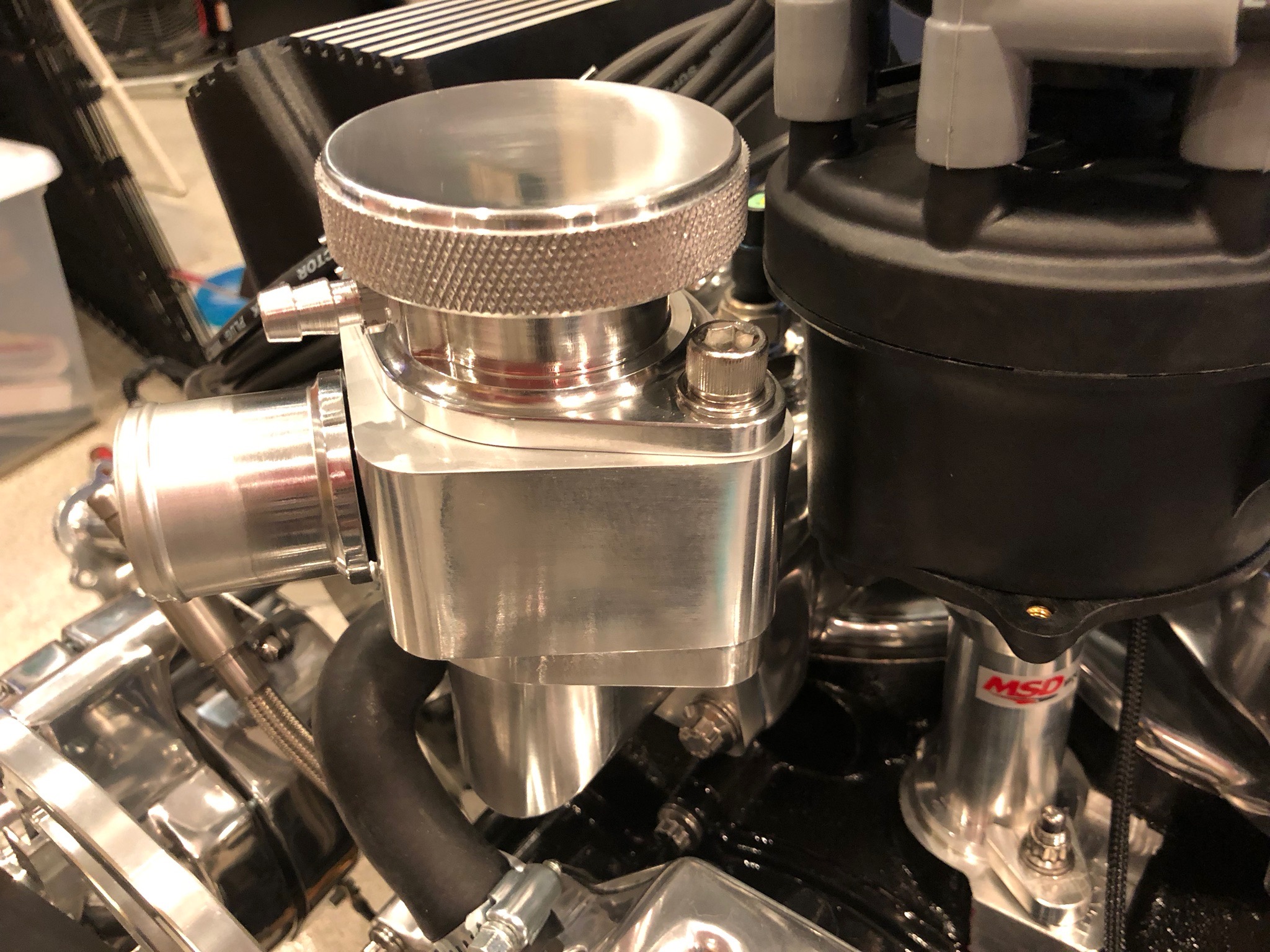
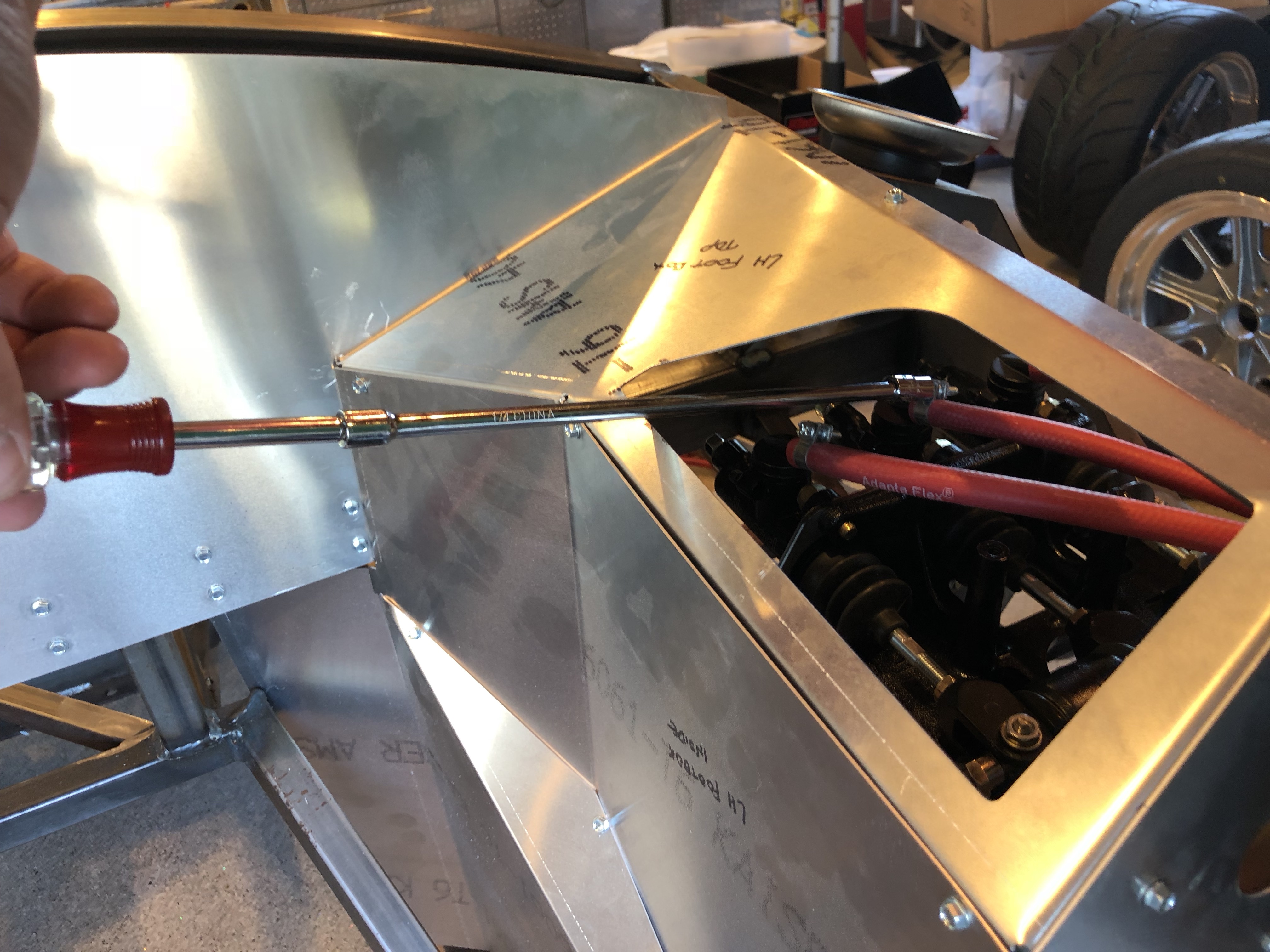
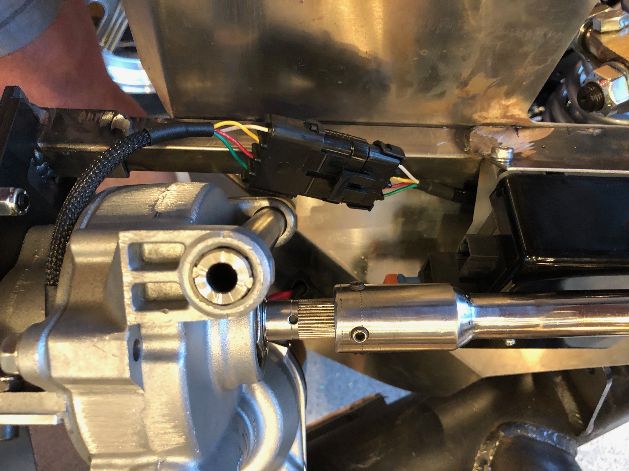
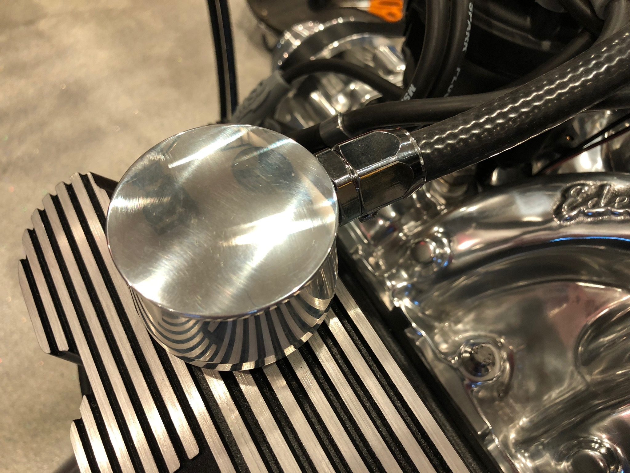
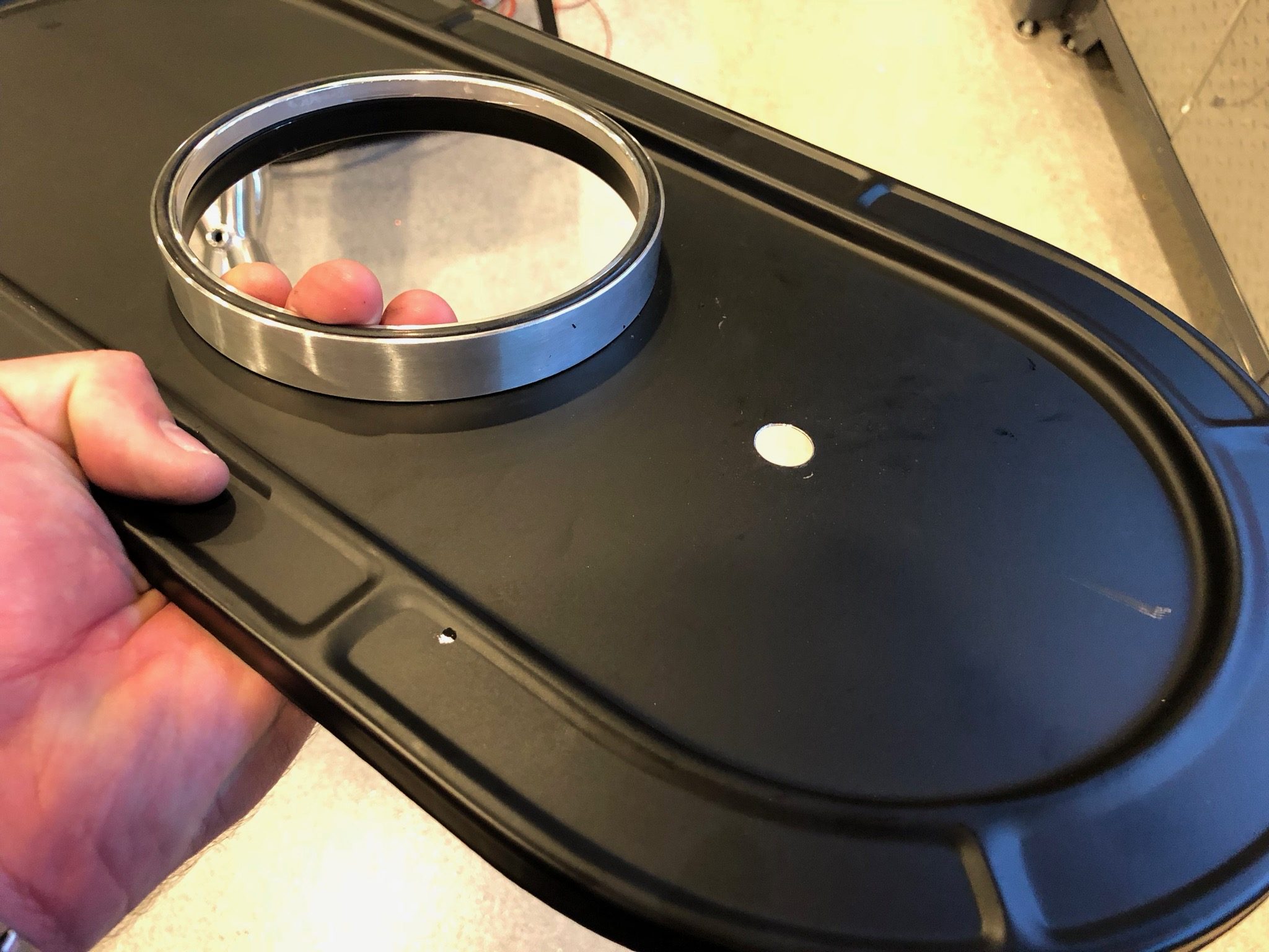
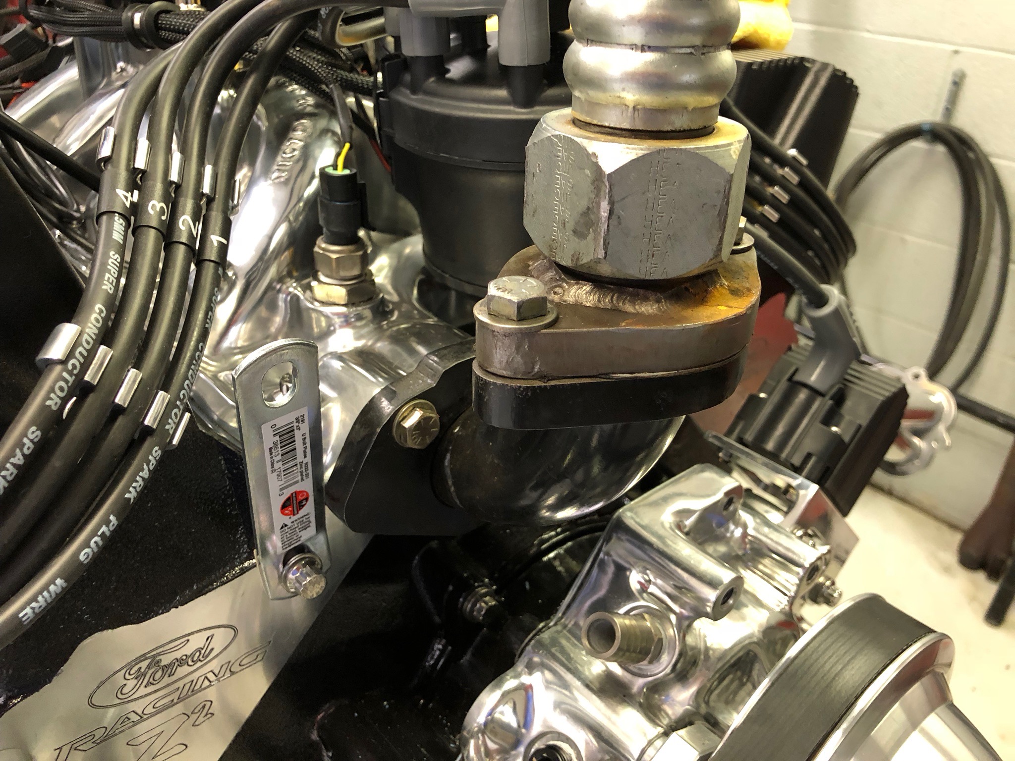
It turns out that I didn’t need to install the water neck as he needed to remove it anyway.

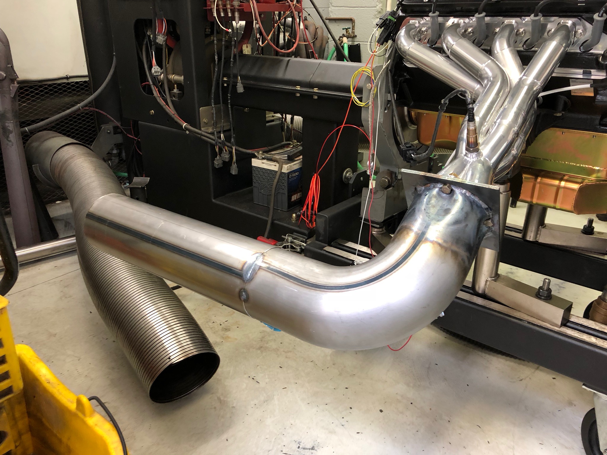
After lunch, Dino welded on the elbows and a piece of straight tubing. This is 5″ diameter tubing. The two elbows and straight pipes ran about $140. Sucks to spend this much on a one-time use part, but there were no other good options.

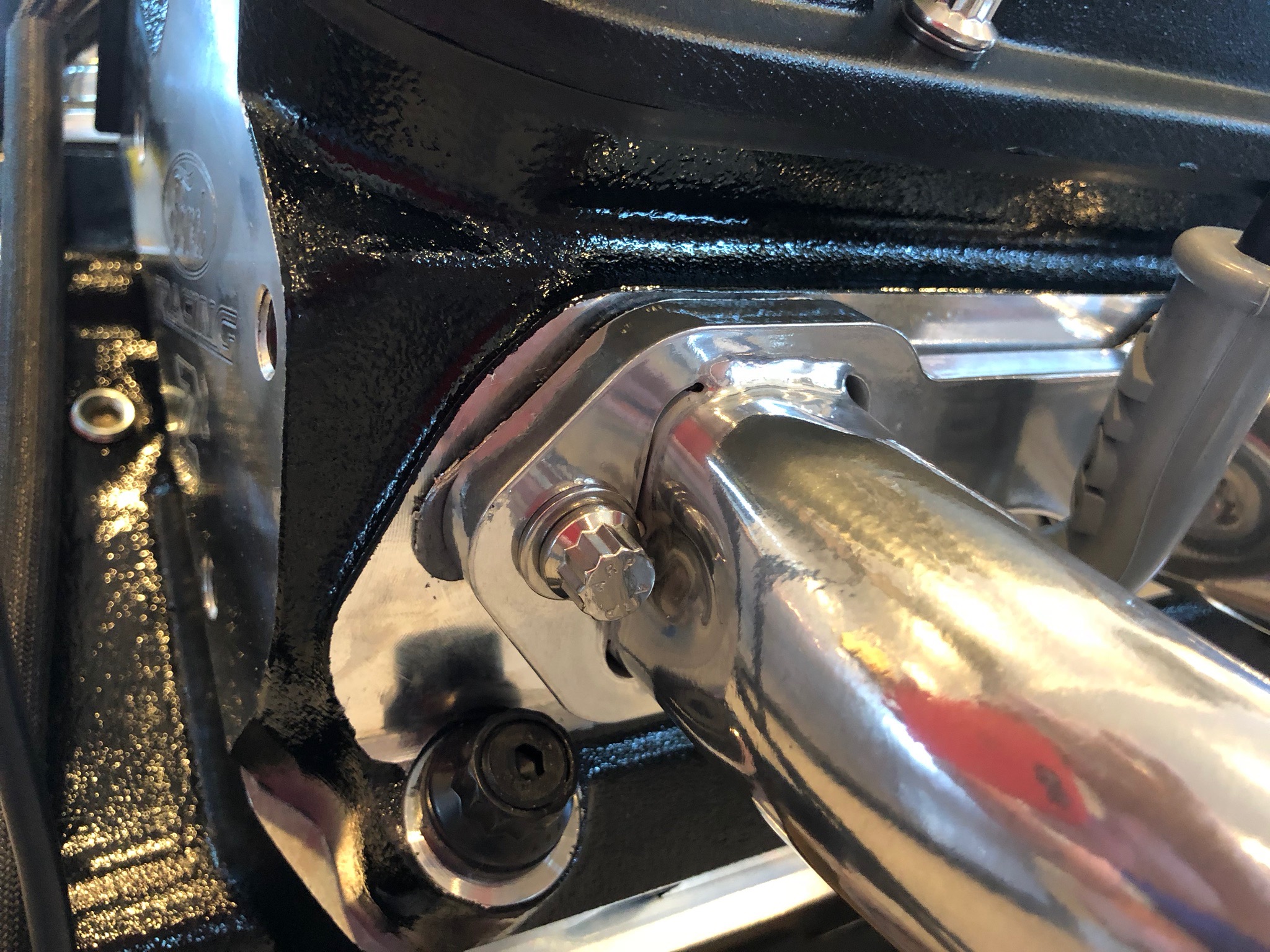
After welding the flange in place, Dino heated up the pipes and dented it in to make room for the bolts. After they cooled down, we bolted them to the exhaust headers.

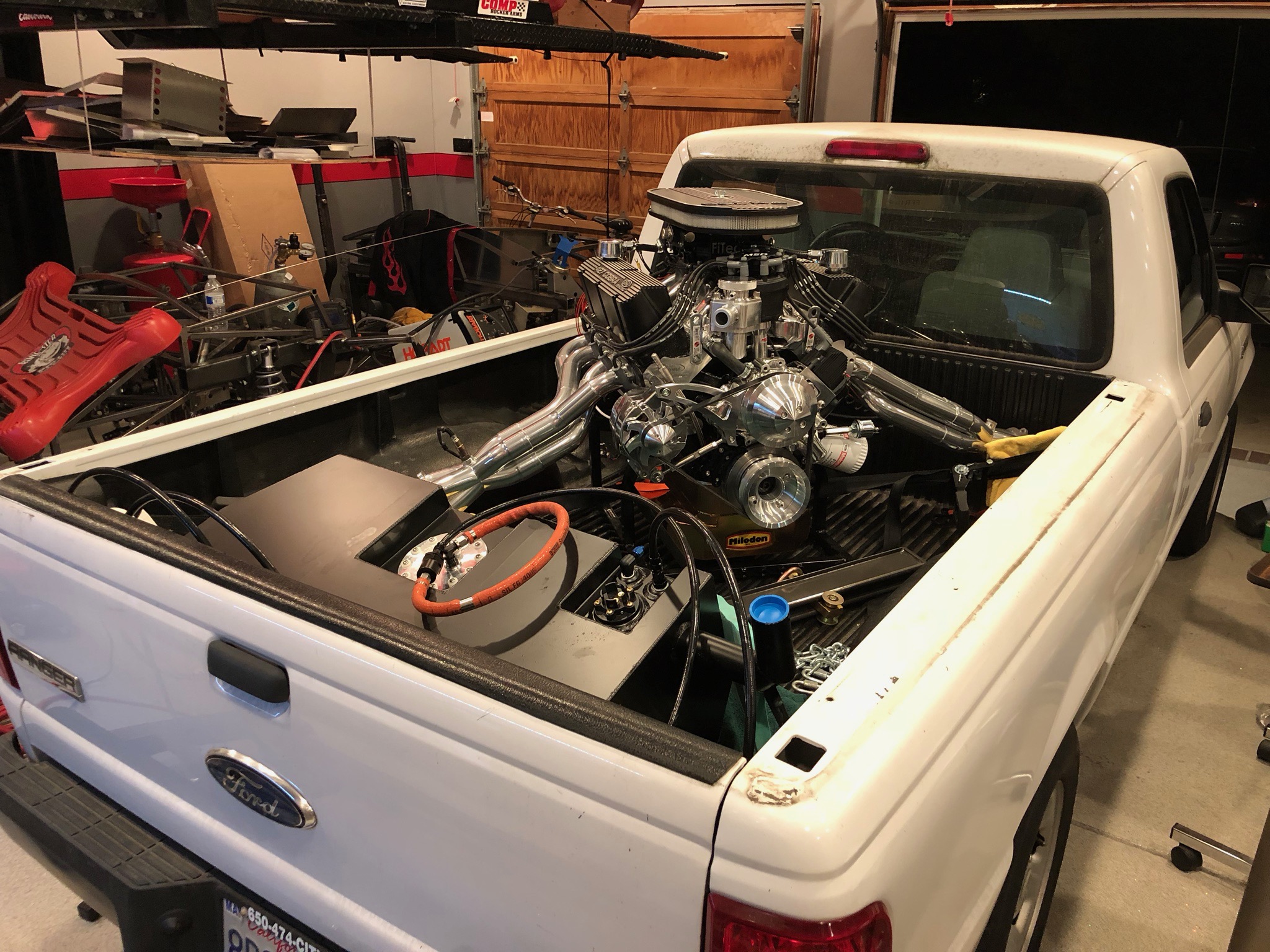
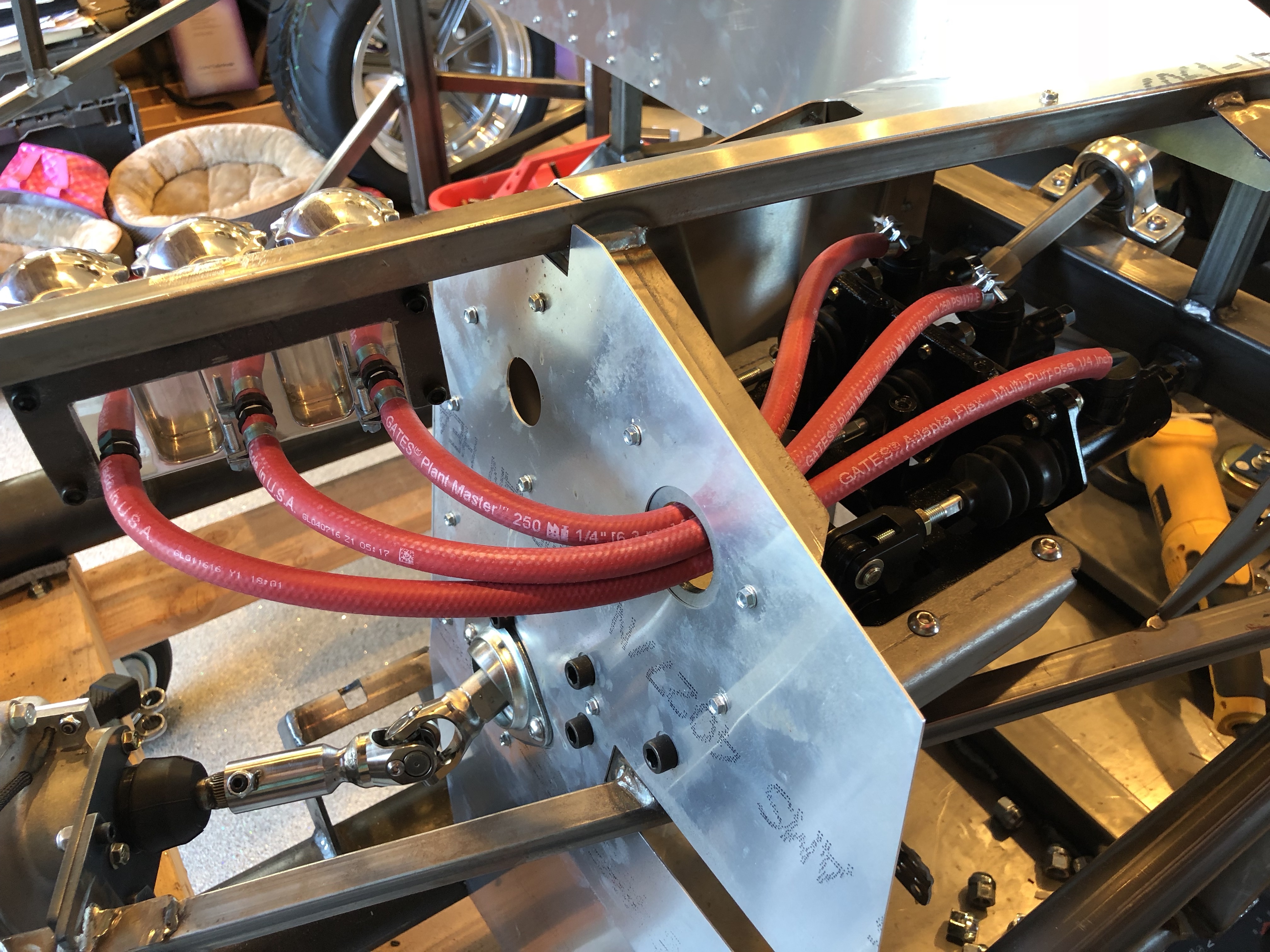
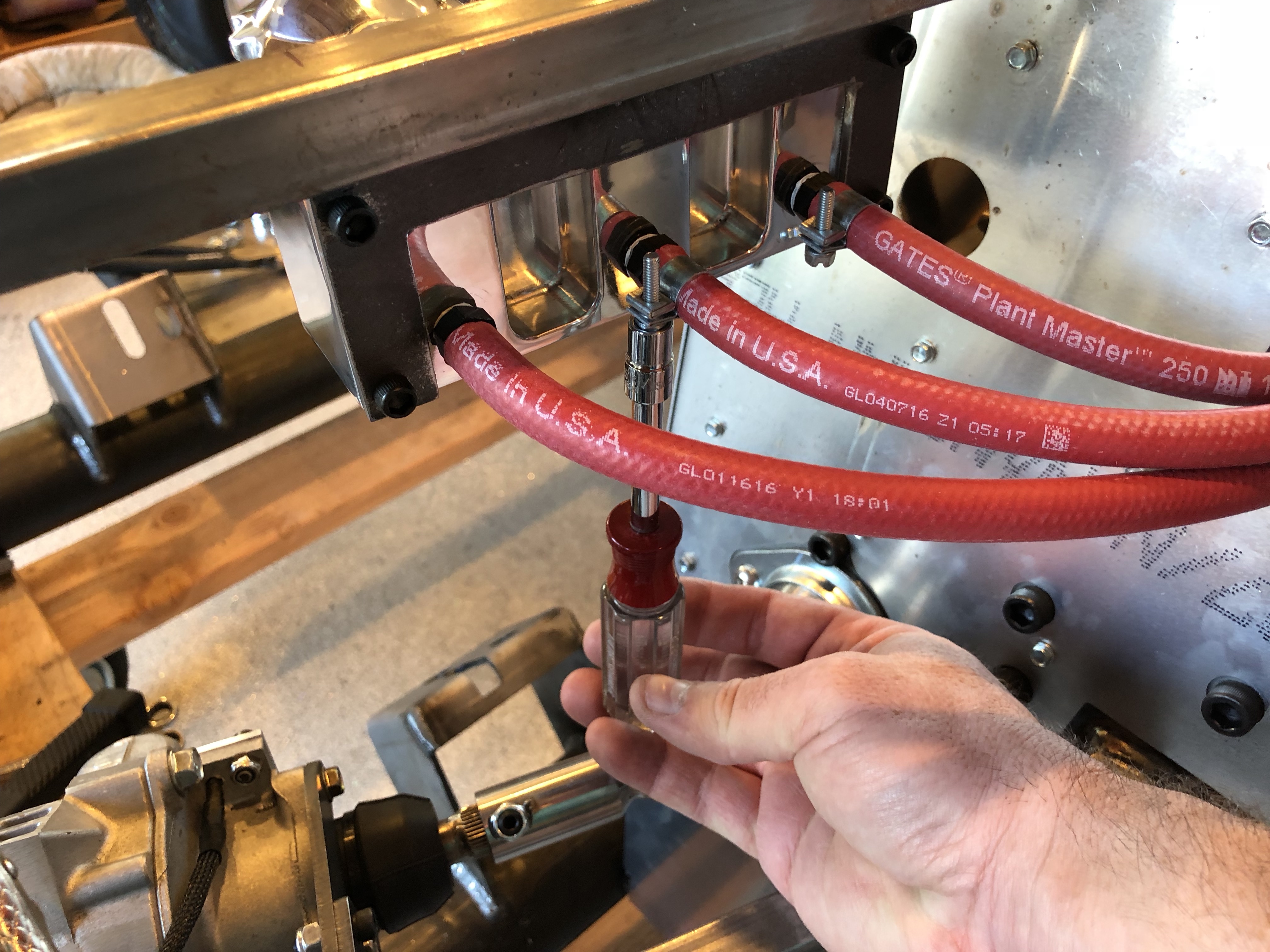
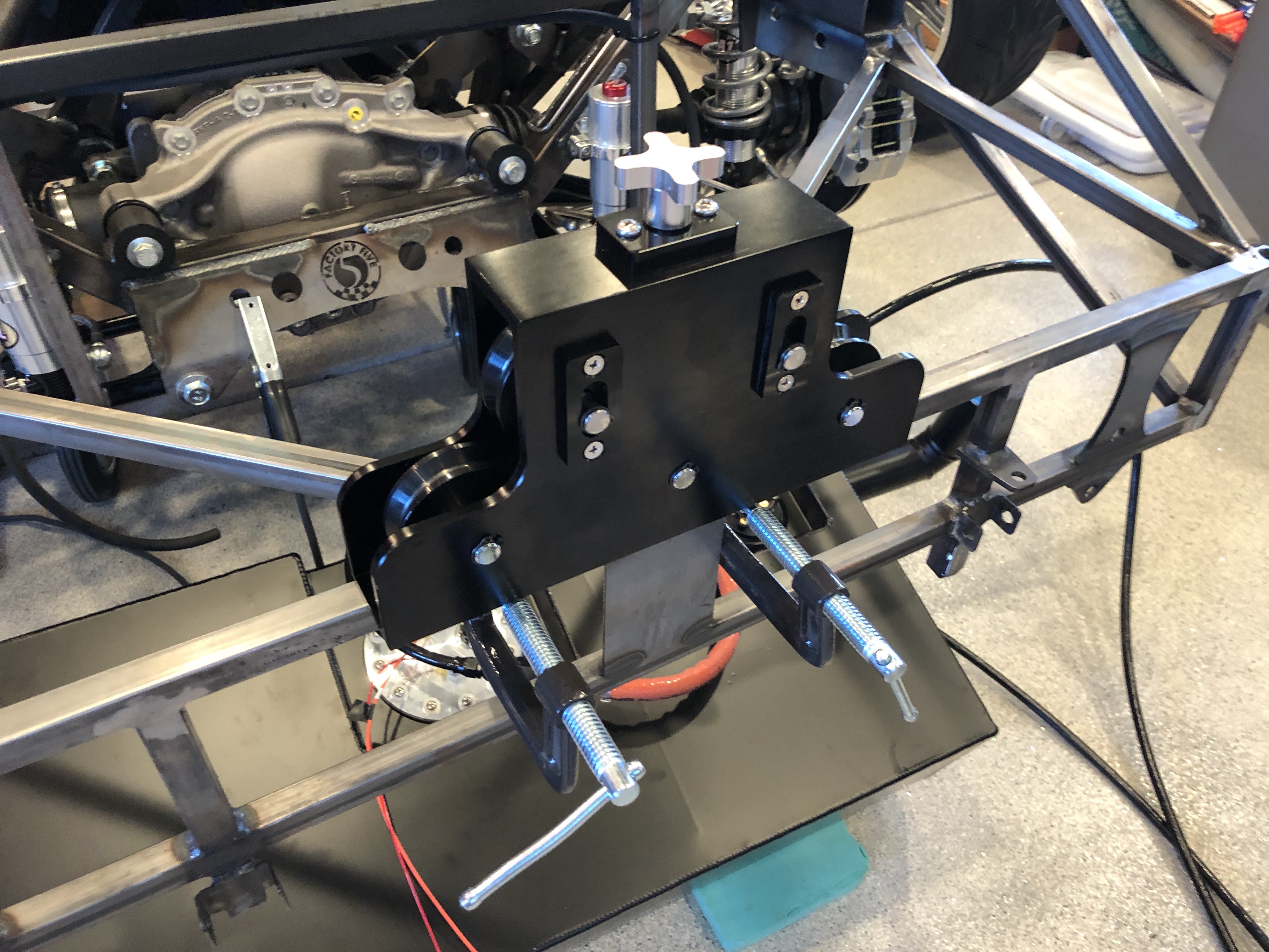
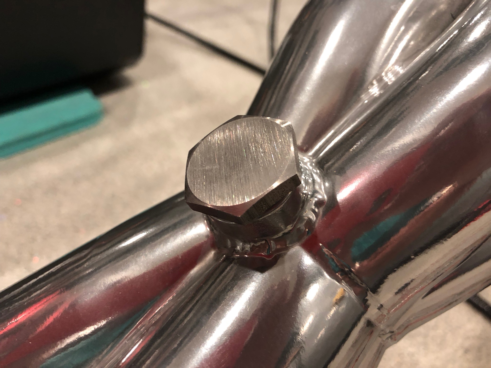
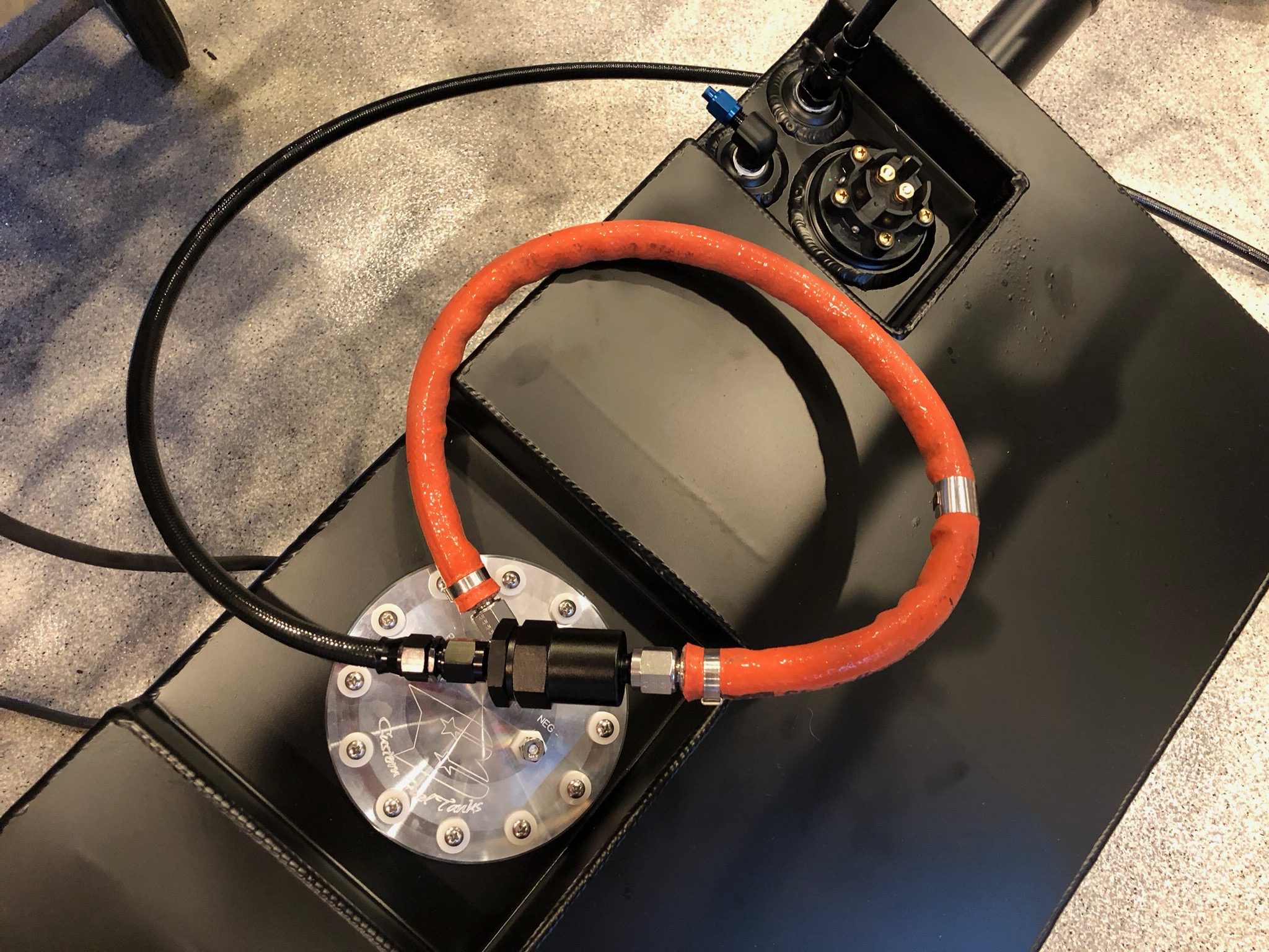
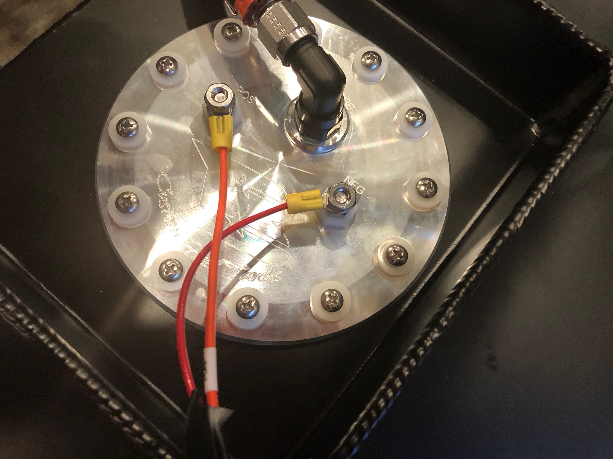
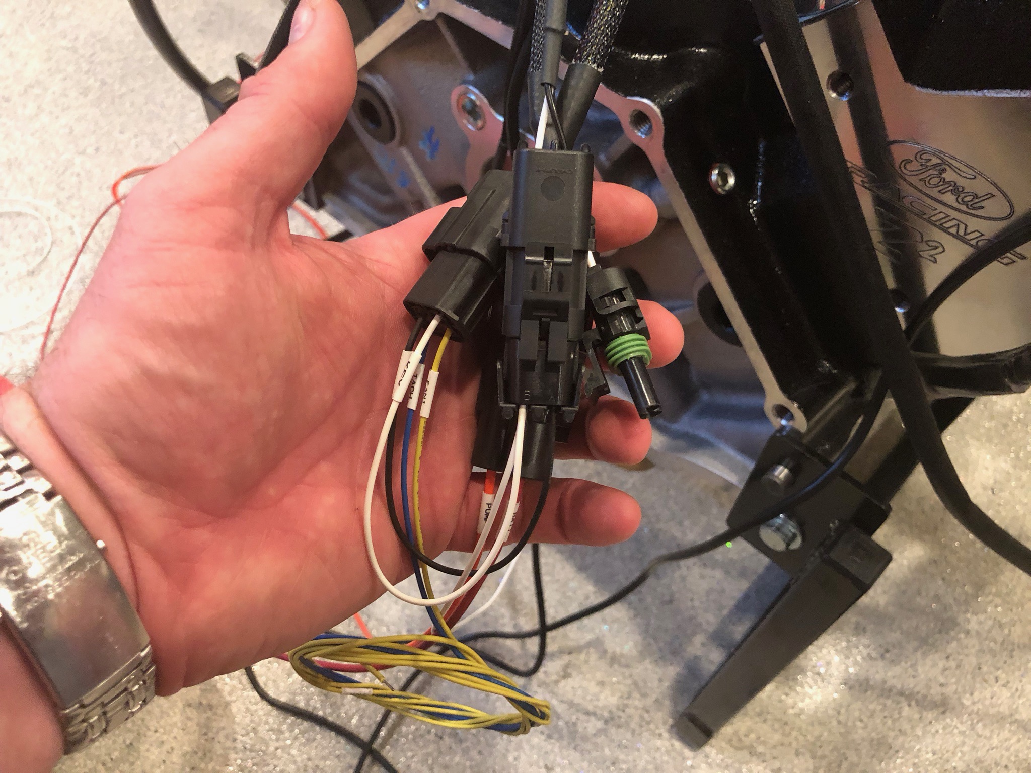
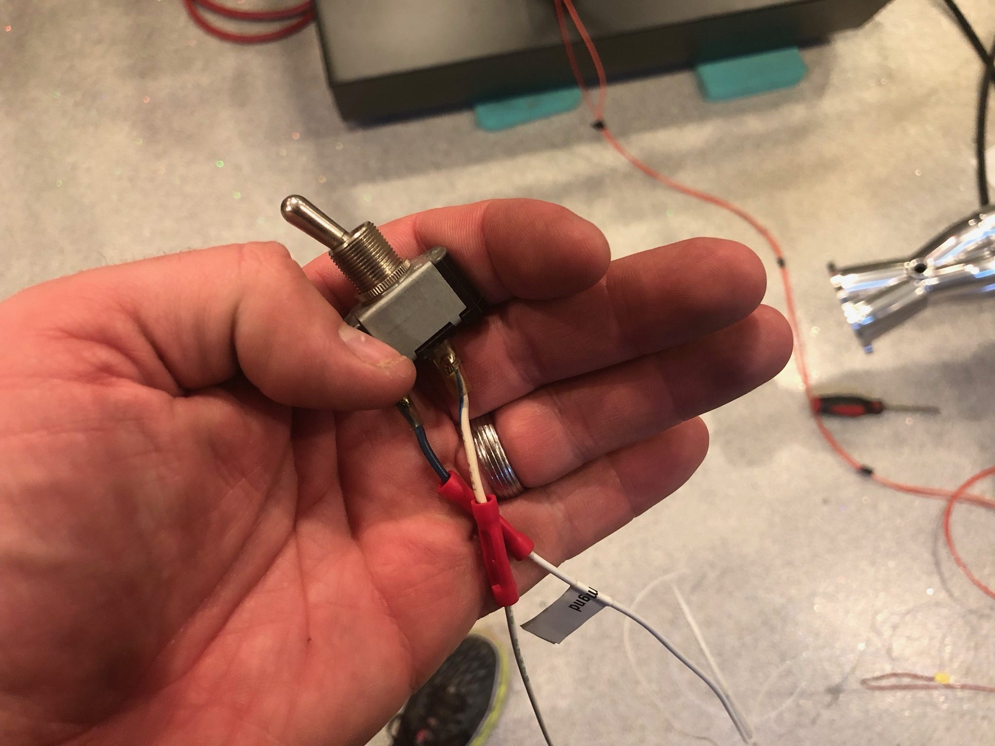
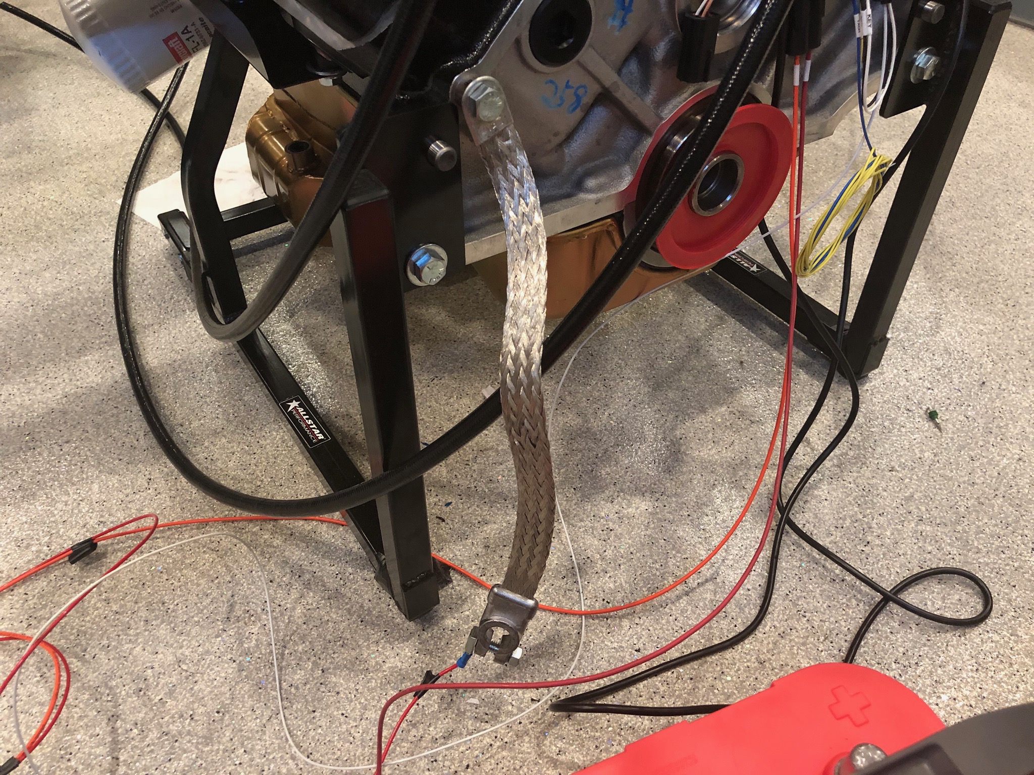
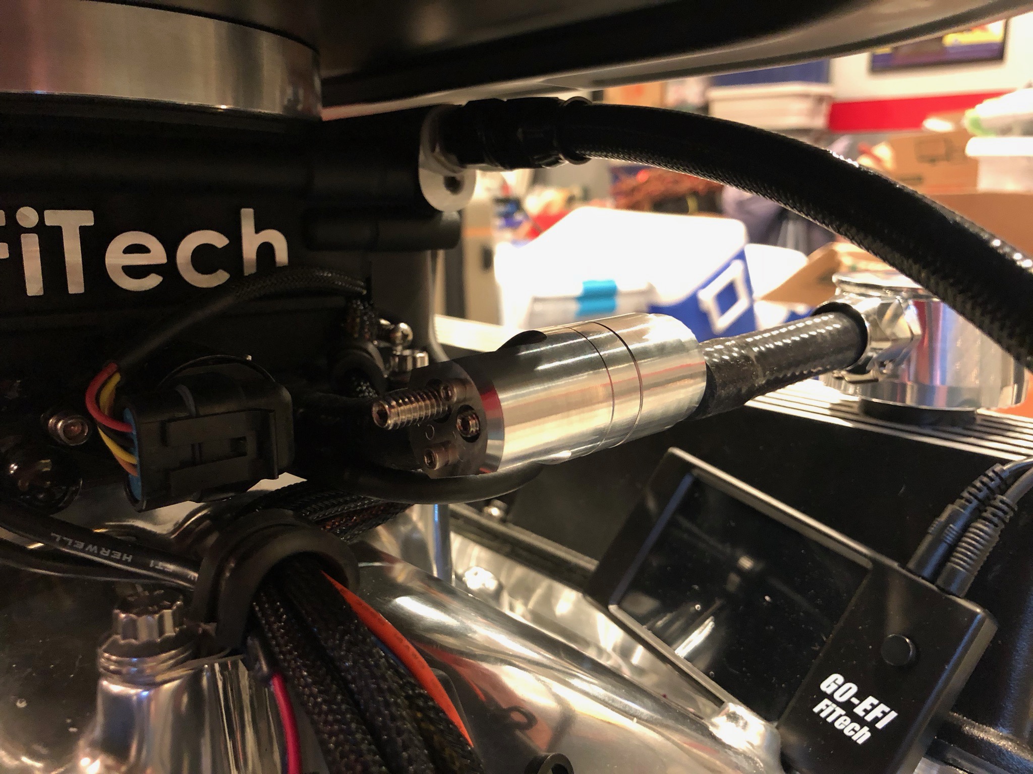
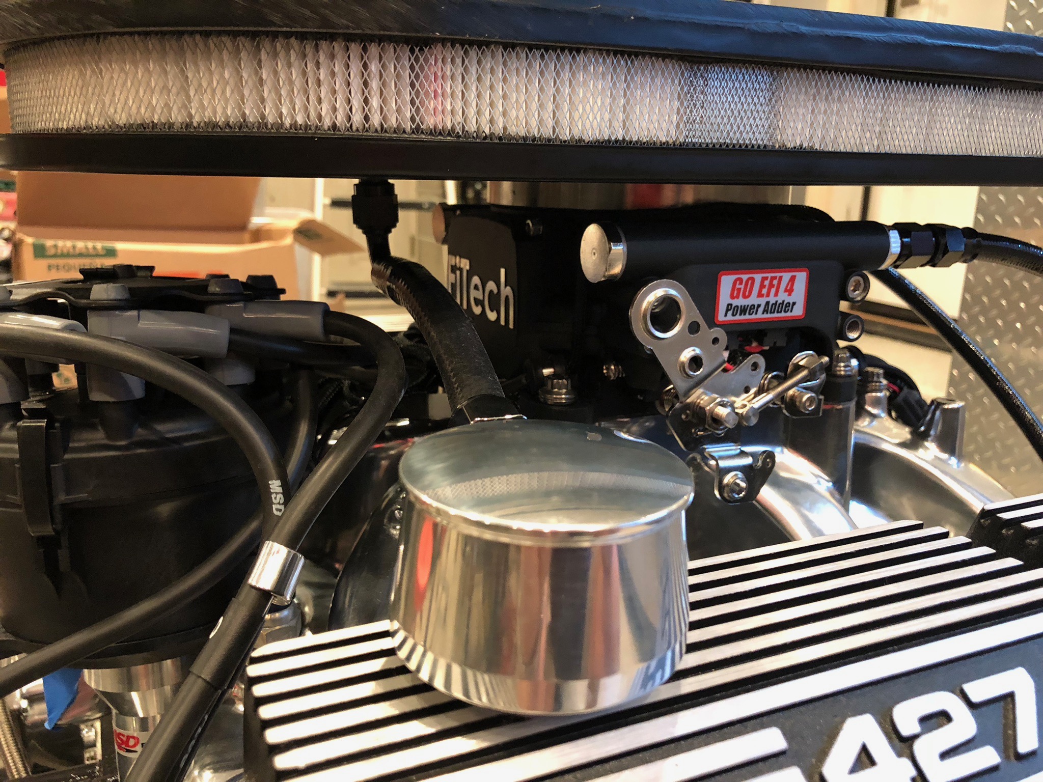
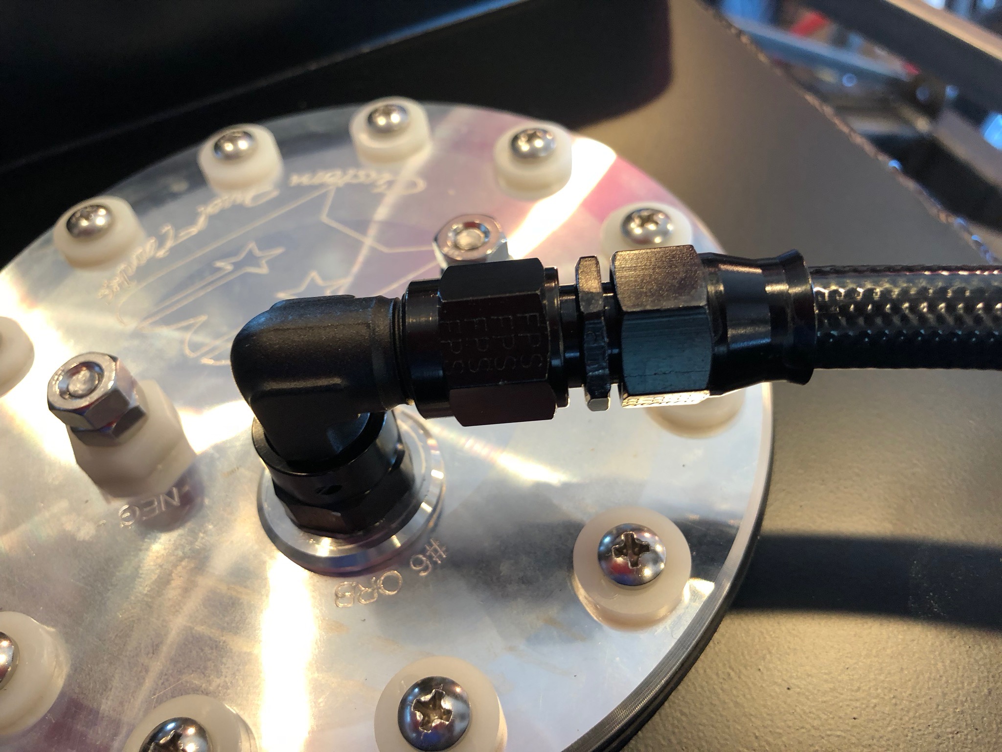
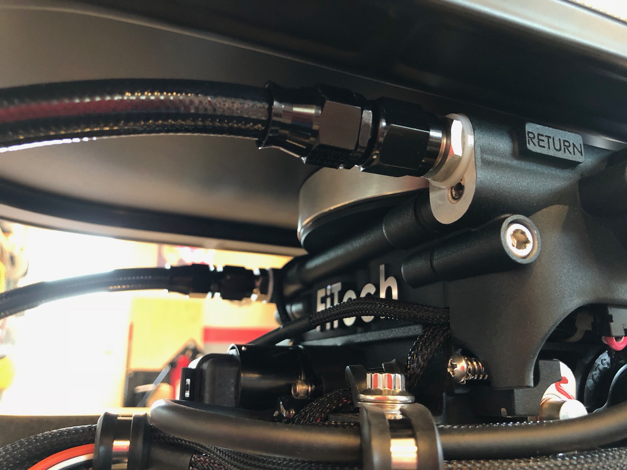
We moved my fuel tank in place and finished up the fuel, electrical and water connections. This thing is ready to run!

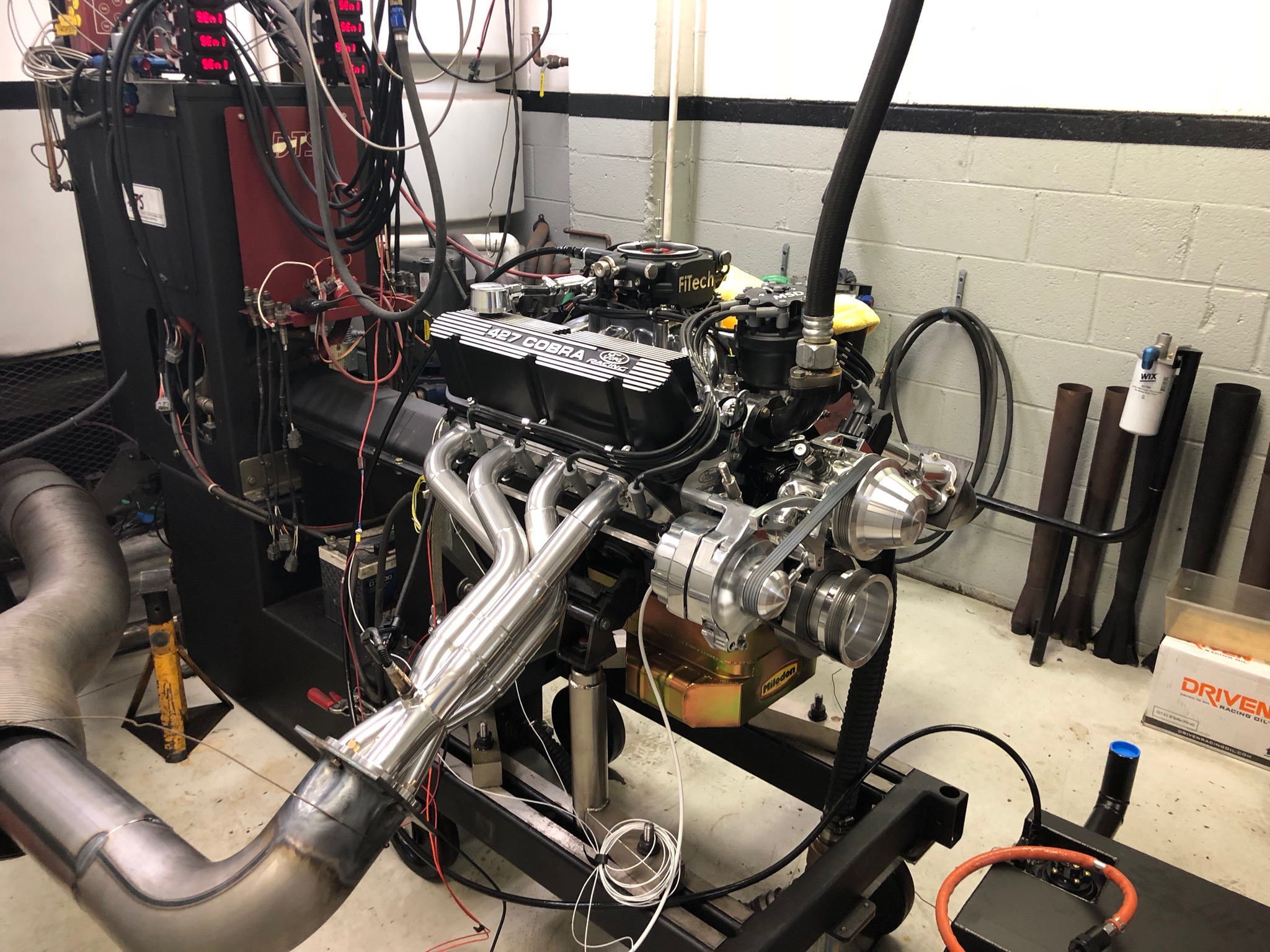
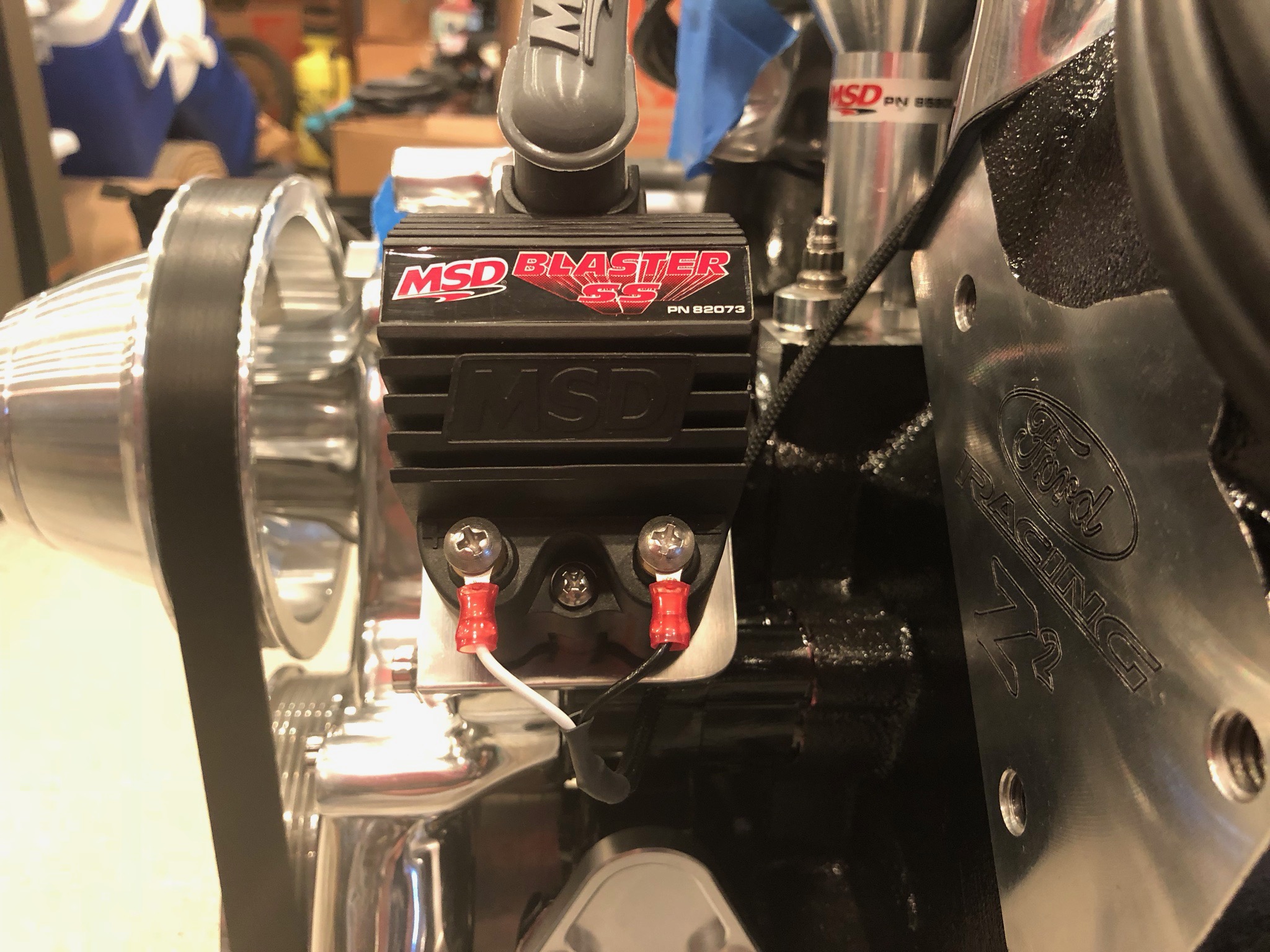
After a couple of failed start attempts, we realized that we weren’t getting spark. I quickly diagnosed that the FiTech config was wrong and I needed to let it know that we were using a two-wire distributor and external coil. Once that was done, the engine fired on the first turn of the crank!

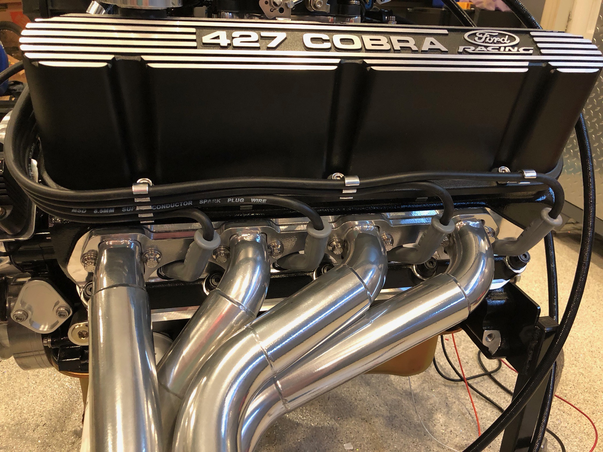
After a 30 minute break-in at 2000rpm, we shut down and pulled all the plugs to confirm there were no problems that needed to be addressed. Everything looked good, so we reinstalled the plugs and got the engine ready for the first dyno pull. Here’s a video of the first pull. The engine had cooled off significantly since we shut down for so long, so we needed to let it warm up for over 6 minutes. In the video, you can see how quickly the engine fires and how smoothly it runs at higher rpms. You can also get a good sense of how lopey the idle is (which is exactly what we were looking for). I was a little concerned that the idle would be too smooth with a 114º lobe separation, but it sounds fantastic. Most of the video is just the warmup; if you want to skip ahead, the dyno pull itself happens in the last 45 seconds.


We did a total of 8 dyno pulls today while adjusting ignition advance and the accel pump setting. We saw about 465hp and 480 lbf-ft of torque on the best run, but I think we’ll be able to improve that a bit when we finish tuning the engine tomorrow.

Loaded Engine for Trip to Dyno Shop

The engine is ready for the dyno shop. A buddy of mine loaned me his pickup truck which is just large enough for the engine and fuel tank. I hooked up the load leveler and raised the engine as high as the shop crane would go. This turned out to be just high enough to back the truck under the engine. My wife backed up the truck while I guided the engine into the bed.

I strapped the engine in securely and loaded the rest of the items into the truck for the ride to the dyno shop tomorrow morning.

Installed Water Neck

The water neck that I ordered from TD Motion over 2 months ago finally arrived. They took quite a bit longer than expected due to manufacturing and shipping delays, but this was worth waiting for. This thing is beautifully machined and eliminates the ugly inline filler port.

I also installed the short thermostat bypass hose you see below the water neck. When I plumb in the heater core, I may see about using hose with AN fittings for all of the coolant hoses, but I need this installed before the dyno run.

You can also see a couple of lifting straps I bolted to the front of the cylinder heads. There are two more on the back of the engine.

About the only thing I dislike about this is that all three parts (lower, middle, and upper) had different finishes. The lower part had a satin, bare aluminum finish. The center part was clear powder coated and the upper part was shiny. I sanded off the clear powder coat (except for a bit that will be hidden under the coolant hose on the far left) and polished all the pieces to match.

Mounted Flywheel

We’re just about ready to take the engine to the dyno shop, so I’m wrapping up a few last minute details. Although this is a neutral balance flywheel, the dyno shop we’re using needs it mounted because they don’t have an adaptor flange to made directly to a Ford crankshaft. This will have to come off after the dyno runs since there is a plate that sits between the block and the bell housing and it will fit behind the flywheel. These bolts call for locktite, but I’m hoping it won’t be a problem to leave that out until it goes on for good.

Brake/Clutch Reservoir, Brake Lines and Front Strut Reservoirs

I installed the top and inside of the driver side foot box because I was considering installing the brake/clutch reservoir in the top of the foot box to ensure the bottom of the reservoirs were level with or higher than the inlet of the master cylinders. After some careful measurements, I determined I could install them in front of the foot box and meet this criteria. I quickly fabricated a bracket out of some 1/8″ steel plate I had and welded it to the chassis tube.

The triple reservoir bolts to this bracket through the holes visible above. The tops of the caps are even with the top of the chassis tube. I went with a triple reservoir so that there are separate reservoirs for the front and back brakes for redundancy. The left two reservoirs are for the brakes; the right is for the clutch.

I connected the reservoirs to the master cylinders with some EPDM tubing. I didn’t have enough hose clamps to finish this, but I have more on order.

I’ve been trying to make sure that everything is accessible for future maintenance. Although access is easy now, with the body on, the only way to access these screws is from below.

I did the same thing with the hose clamps in the foot box. With the body on and the foot box riveted in place, the only access with either be from below or through this hole. I made sure I could access all of the hose clamps from above before tightening everything down.

With the reservoir and master cylinder plumbing complete, I continued fabricating the hard lines. I welded on the front tabs near the aft end of the holes in the F panels. I’ll finish cleaning up the welds before the chassis is finished.

With the tab welded in place, I wanted to make sure that the brake line didn’t contact theelectric power steering support.

Fortunately, I got lucky and there’s about 1/8″ of clearance here.

I clamped the tubing straightener to the aft end of the chassis so that I could straighten out some pieces of stainless brake tubing.

I started with a fairly short piece of brake line that connects the front left fitting to a tee that will sit on top of the x-frame tubing.

Then bent up a mirror image piece for the other side.

This one runs along the top of the x-frame to the same tee.

A final piece will run from a bulkhead fitting on the front of the driver’s foot box to the other side of this tee.

With the hard lines in place, I installed the fitting in the brake caliper and connected a piece of stainless brake hose.

I then did the same thing on the other side.

Finally, I decided to mount the front strut reservoirs. I decided to clamp the tubing to the screw that is used to secure the strut reservoir. To do that, I need to use a longer clamping screw, but the ones I had have a section without threads near the head. I used a 1/4″ reamer to remove a portion of the threads.

This lets me install the longer screw.

I then welded the steel brackets to the vertical pillars. Excuse the ugly welds, I’ll have to clean these up when the car is disassembled.

I slipped the strut reservoir in place and tightened down the clamping screw. I then used a cushion clamp to secure the hose to the back side of the clamp.

Installed Exhaust Headers

I mentioned in an earlier post that I needed to use longer screws to attach the exhaust headers. Because we stepped up to 1.75″ tubing and the pipes start curving as soon as they leave the flange, some of the longer screws can’t even be inserted through the mounting holes.

I used a carbide burr to slightly relieve the inside of the hole, just enough to allow the bolts to slip in.

The tubing also prevents using a socket to tighten the bolts, so I wasn’t sure how I was going to torque these. In fact, the only wrench I had that would fit over the bolts without contacting the tubing was this old S-K box end wrench I got from somewhere. I thought I was just going to have to guess at how much to tighten these. Fortunately, the other end of the wrench fit perfectly over the 3/8″ square drive on my torque wrench.

One of the tricks with torque wrenches is that if you use an extension mounted at 90º to the handle, you don’t need to adjust the torque setting to compensate for the extension. You can see here that the wrench made it easy to access the bolts.

After figuring out the how to torque the bolts, it was pretty straightforward to get all 16 bolts in both headers installed and tightened down.

After installing the headers, I installed a stainless steel plug in the left side O2 bung.

Prepping Engine for Dyno Shop

I’ve got a handful of details left to wrap up before we can run the engine at the dyno shop. First up, I needed to plumb the fuel filter between the fuel pump and the throttle body. I had a few scrap pieces of hose laying around from my airplane build, so I used one to insert the fuel filter into the supply line.

I also temporarily wired up the fuel pump to the FiTech unit. I’ll replace these terminals with better ones during the final wiring on the car, but this is what I had laying around that fit these large studs.

I also needed to wire up the ignition coil to the FiTech unit since it controls the ignition timing. Most of the car will be wired with automotive TXL insulated wire since that’s what comes in the Infinitybox wiring harness, but I don’t have any of that right now. I used some MIL-W-22759/16 wire I had laying around (which is better than the TXL wiring anyway). This cable snakes under the ignition coil (where it will be secured with a cushion clamp) and up behind the distributor where it follows the rest of the wires around the right side of the throttle body to the back of the engine.

The coil needs to be connected to two wires coming off one of the other FiTech connectors, so I looped them back. The white wire will also be connected to the switched side of the ignition switch.

Since I don’t want to mess with the key switch now, I just rigged up an old toggle switch to turn the ignition on and off.

I also temporarily attached the ground strap to the engine block. At the other end is the red wire that goes to the fuel pump ground. I didn’t have any 18+ ga black wire around, so I used red and flagged it with some black electrical tape. None of this will end up in the car.

While I had my tools out to install the WeatherPak connectors on the back of the engine, I connected the electric power steering motor to the controller.

Installed PCV Valve

I received the M/E Wagner PCV valve in the mail today. I cut a couple of pieces of the silicone hose and had it installed in just a few minutes.

The inlet on the bottom of the unit is aligned with the breather cap and the outlet on the side is aligned with the nipple on the throttle body.

The adjustment screws will be easy to reach from the left side of the engine by reaching under the air cleaner. Getting to the calibration port may be a little more challenging as it’s basically on the bottom of the unit. Although these hoses are under vacuum, I will probably add some worm clamps to them.

Engine Breather

The valve covers came with a Ford Racing breather cap, but we want to have a matching breather cap on one valve cover and PCV valve on the other. This also has a weird, crinkle finish on it that doesn’t match anything else on the engine.

Billet Specialties sells these really nice PCV valves that fit in the 1.25″ valve cover holes. My plan was to remove the PCV valve from one of them and use it as a breather, but a friend of mine recommended an M/E Wagner adjustable PCV valve, so I’m going to pull the PCV valve from both of them.

After unscrewing the base, the PCV valve can easily be removed with a pair of snap ring pliers.

I fit a piece of silicone hose with chrome fitting on the end and installed it in the valve cover.

The breather needs to have access to a filtered air supply, so I drilled a 9/16″ hole in the air cleaner base.

In the hole, I installed a straight bulkhead fitting and a 90º hose adapter.

It’s is a pretty straight shot from the breather to the hose fitting. When the M/E Wagner PCV valve arrives, I’ll plumb it inline between the other cap and the throttle body.

Fabricated Temporary Fuel Hoses

In preparation for running the engine at the dyno shop, I fabricated a couple of hoses. I’m using Fragola stainless steel reinforced conductive PTFE hoses with a black nylon covering. For the dyno run, I just need a supply and return hose, so I cut the 20′ hose in half and installed straight fittings on each end.

Here’s where the supply and return lines attach to the back of the throttle body.

We also received our headers from GP Headers. These are ceramic-coated, stainless steel headers with double collectors so that the O2 sensor can be installed in the engine compartment.

These are really beautiful, especially compared with the ones from FFR. I installed the FiTech O2 sensor in the right side bung since the passenger side of the engine compartment is much less crowded.

The GP Headers have a much thicker flange (3/8″ vs 1/4″), so the 3/4″ bolts that came with the engine bolt kit aren’t long enough. There is only about 1/4″ of thread engagement in the block with these bolts, so I’m going to see if ARP will exchange these for 1″ bolts.