Finished up Distributor Wiring and Fuel Pump Installation

I received a new order from Summit Racing with some additional wire separators.

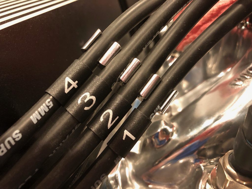
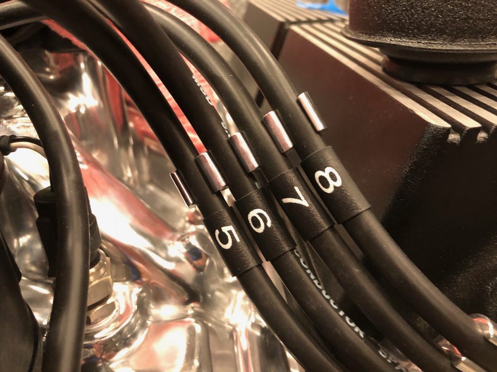
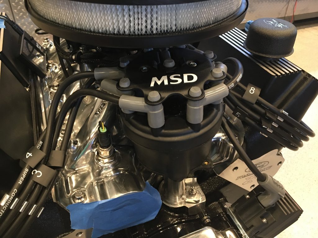
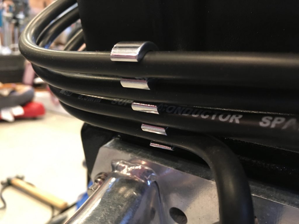
I used one on each side to keep the wires organized as they make their way up to the distributor. After installing the wire separators, I slid the heat-shrink wire labels in place and shrunk them down.

Here’s the other side.

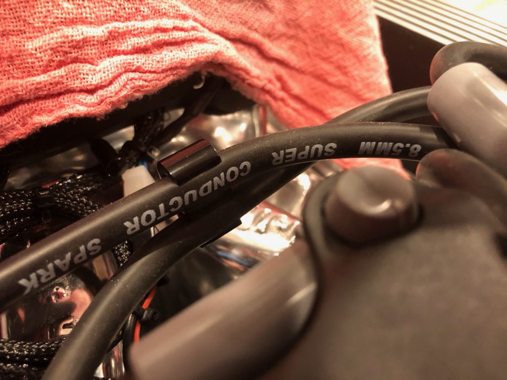
I used a two-conductor wire separator behind the distributor to tie the #4 and #7 wires together. For some reason, they didn’t stock polished, two-conductor separators on Summit, so I ordered black anodized ones. This will largely be hidden under the air cleaner though, so I think black will be just fine. I can always sand off the anodizing and polish it if it’s too visible.

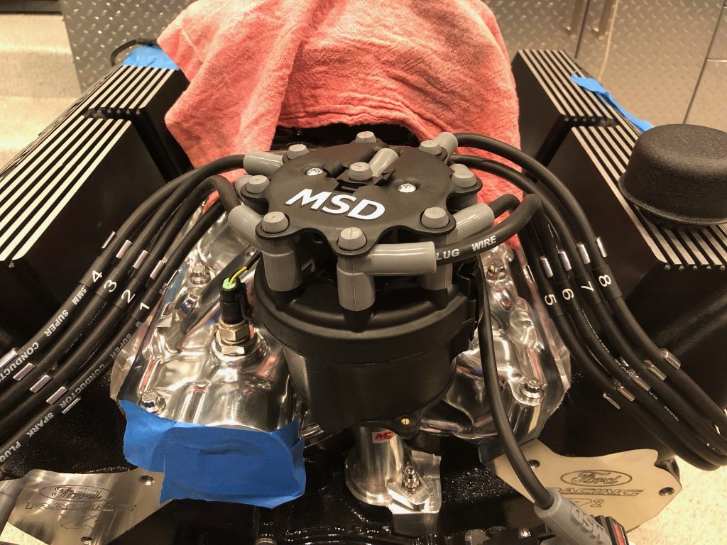
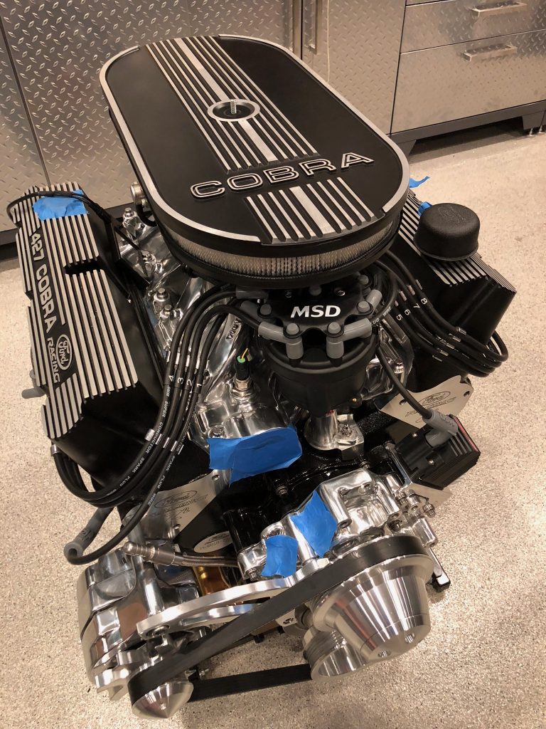
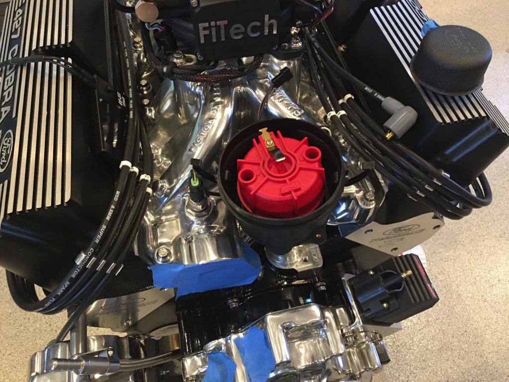
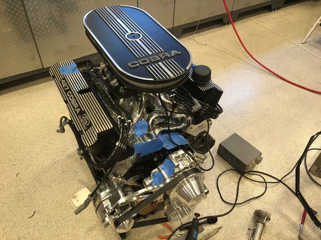
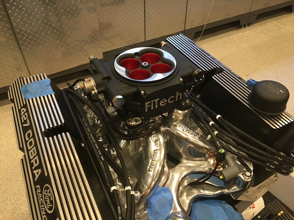
Here’s a shot of the whole engine with the distributor wiring all wrapped up. Only a few remaining details to wrap up before I can get the engine to the dyno shop.

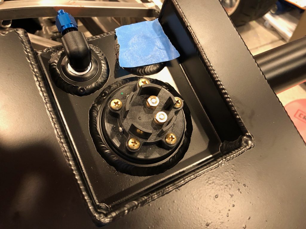
I also received and installed the Classic Instruments tube type fuel level sender. This is a 0-90Ω sender that is compatible with the gauges from FFR. The tank is 10.75″ deep here, but this sender is only 10″ long below the flange. That leaves 3/4″ of unmeasurable fuel below the sender; given the taper of the bottom of the tank, that’s probably only 1-2 gallons of fuel. I’m fine  with a 1-2 gallon fuel reserve below the empty reading on the fuel gauge.

Installed Distributor

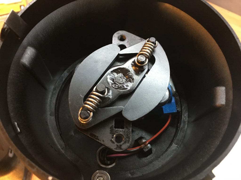
The FiTech EFI system controls the ignition advance, so the mechanical advance has to be locked out. I started by removing the springs and weights.

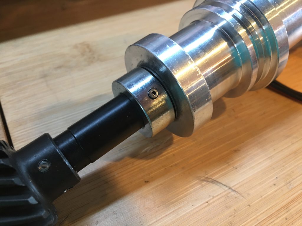
The roll pin on the retaining sleeve has to be driven out so that the shaft can be pushed up in the distributor.

With the shaft pushed up, it can be rotated 180º so that the advance stop bushing pin can be dropped into a hole in the advance plate which locks the two pieces together. Afterward, the retaining sleeve can be slid back in place and the roll pin reinstalled. Now there are no moving parts in the distributor (other than the shaft and rotor).

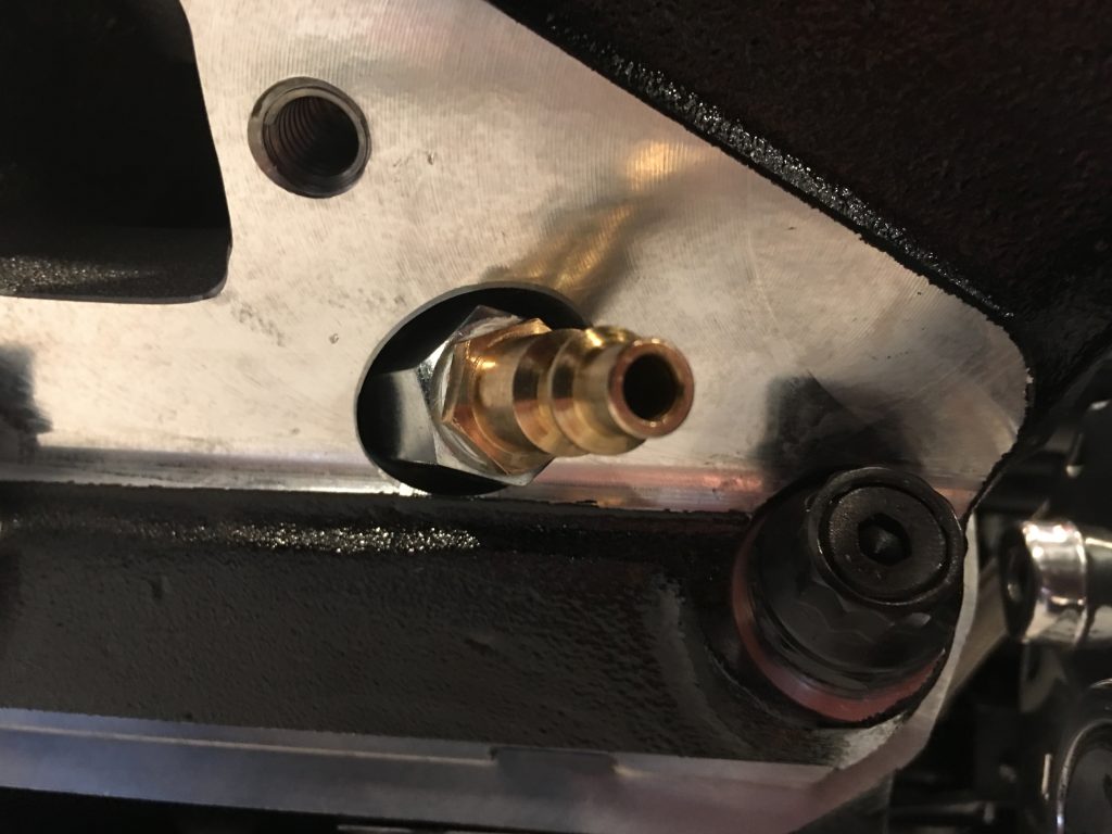
In order to install the distributor in the engine, I needed to reset the engine to 12º BTDC on the compression stroke of the #1 engine. I installed the air fitting in the #1 cylinder so that I could tell when it was on the compression stroke.

I rotated the engine until it was 12º BTDC.

I then stabbed the distributor into the block. I needed to adjust the oil pump driveshaft a couple of times until the distributor dropped into place.

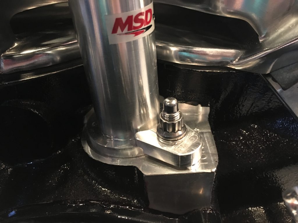
I then installed the distributor hold down clamp to lock the distributor in place.

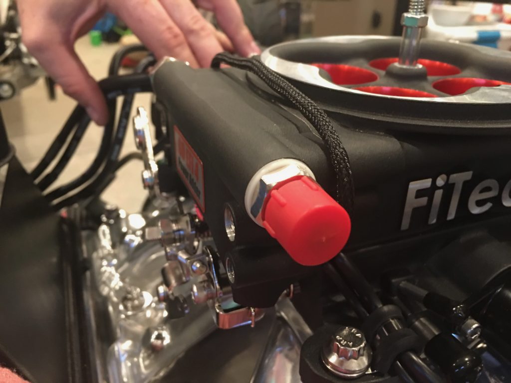
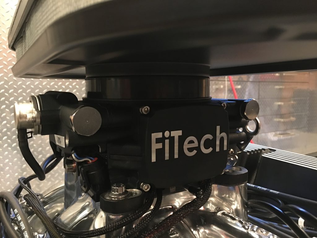
The cable from the FiTech unit leaves a bit to be desired. The cable is surprisingly short and for some reason comes out of the back of the unit. Without extended the wires, it really can only run around the left side of the throttle body or over the top. There is no way to run around the side without interfering with the throttle linkage, so I run the cable over the top. I really don’t know why FiTech doesn’t have this cable coming out of the front of the unit to avoid this problem.

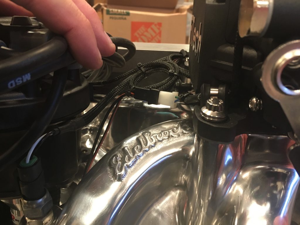
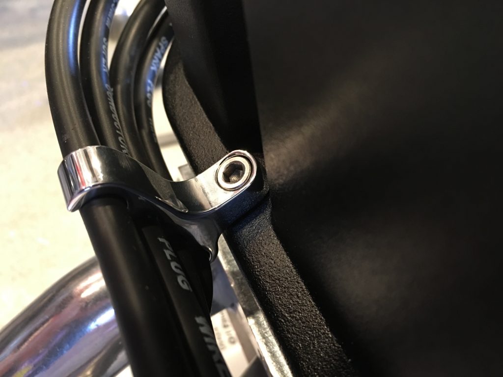
On the right, you can see the distributor control cable coming down from the top of the unit and secured with an Adel clamp to prevent it from moving. I pulled the coolant temperature cable out from underneath the intake runners and coiled up the extra on the front of the throttle body. I also installed the secondary coolant temperature cable that connects to the dash gauge. Since we’re installing a fairly long air cleaner, virtually all of this wiring will be somewhat hidden.

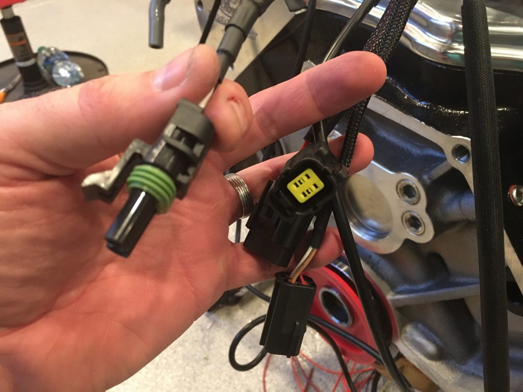
I also cut the cable going to the coolant temperature gauge and installed a weatherpak connector at roughly the same position as the other connectors. I want to easily be able to disconnect the engine from the car without having to pull wires through the chassis.

I cut all of the ignition wires to length and crimped terminals on them. I still need to order a couple of wire separators to neaten the wires up a bit and then I can shrink the wire labels onto the wires.

Fuel Injection Wiring and Fuel Tank

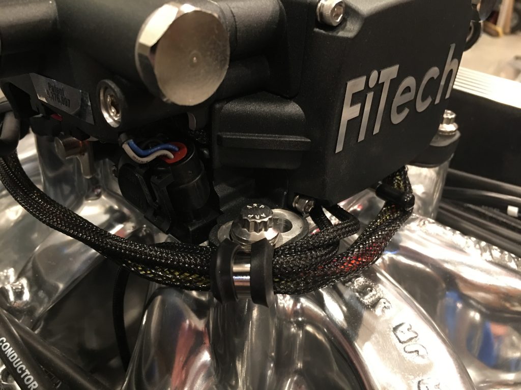
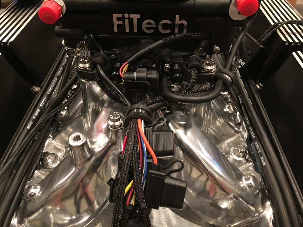
I picked up some stainless steel cushion clamps and used a few to secure the FiTech throttle body wiring. There are three bundles of wires coming off the front of the unit (including the one that drops under the intake runners and connects to the coolant temperature sensor).

The remaining two, plus all of the wire bundles that come off the back of the unit are collected into one cushion clamp that is centered behind the throttle body. Fortunately, there are a couple of unused threaded bosses on the back of the throttle body that can be used to secure things. Once the air cleaner is installed, these should be nearly invisible.

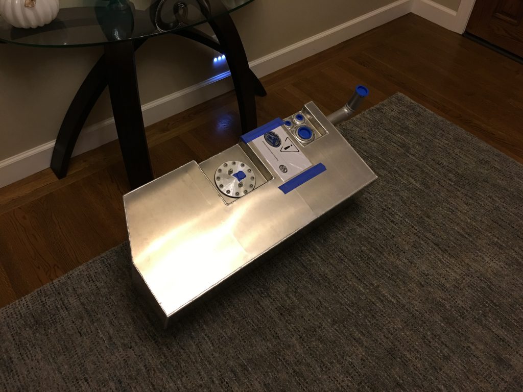
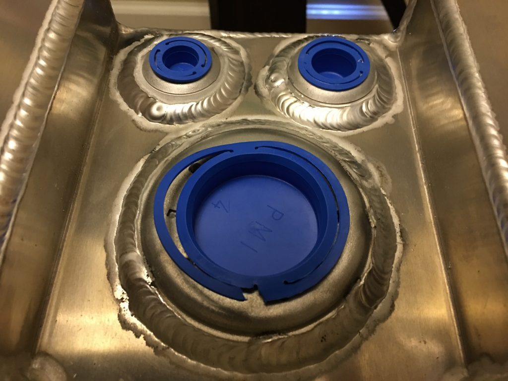
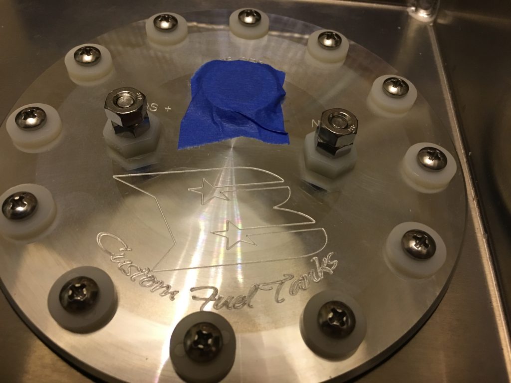
Our Boyd Welding fuel tank showed up today. This is a beautiful piece of work and comes with an Aeromotive 340 Stealth fuel pump pre-installed.

The right side of the tank contains fittings for the fuel return and vent (the small fittings at the top) and the fuel level sender (the large fitting at the bottom). I’ll need to determine which fuel level sensor should be installed here since the one from FFR doesn’t look like it’s compatible.

The fuel pump is installed behind a custom machined mounting plate that has the fuel outlet fitting and electrical connections.

Alternator Ground

Work is going to slow down on the car over the next week or so due to family commitments, but I did manage to get a little time on it today.

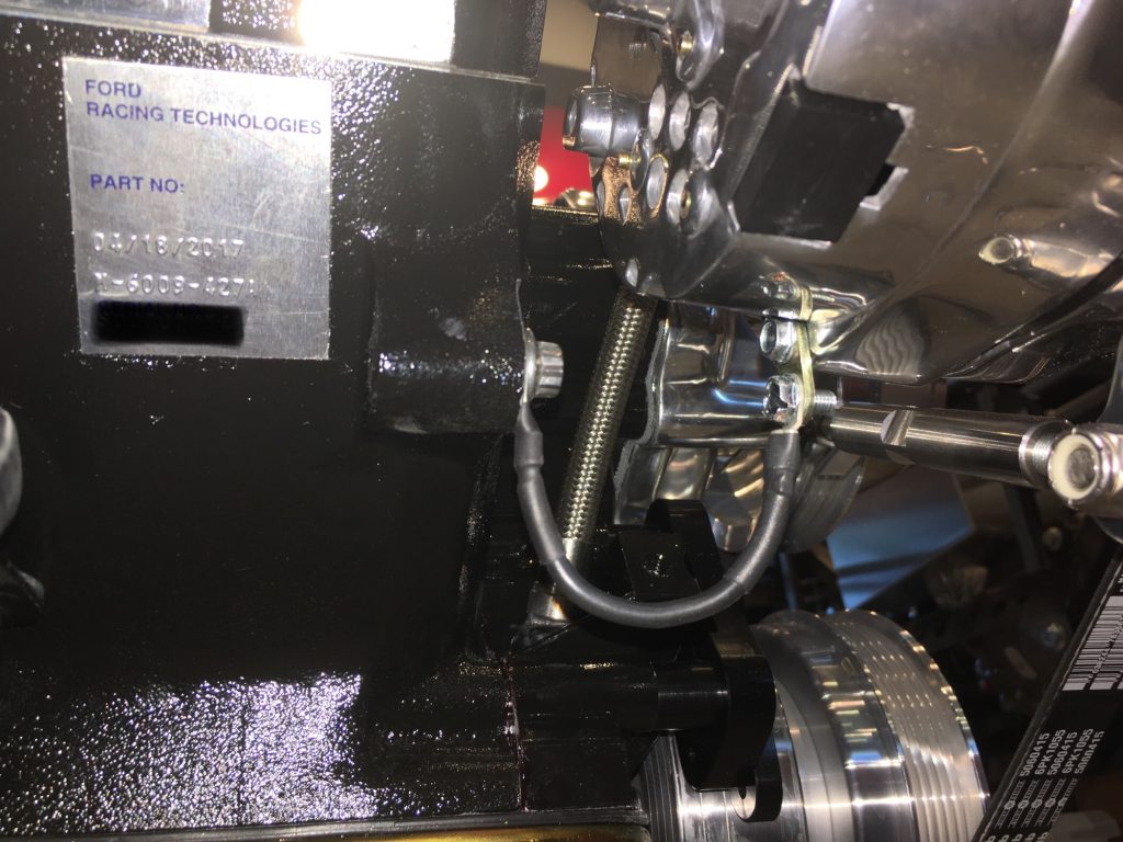
I moved the grounding tab on the alternator to the lower left bolt so that I could run a short grounding wire over to the block. The alternator came with a pretty long wire that I just cut and crimped a new connector on. This should be out of the way of everything.

Air Cleaner Spacer and Steering

When I ordered the hold down kit, I decided to go ahead and pick up an aluminum spacer for the air cleaner. I really need a 3/4″ high spacer, but the only options were 1/2″ and 1″, so I picked up the 1″ and removed 1/4″ from the height on the lathe.
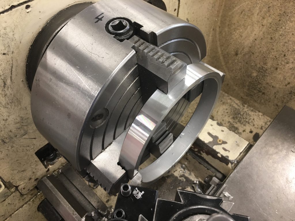
I then cut a new recess on the inside 1/2″ down from the top and opened it up a few thousanths wider than the air filter base flange.
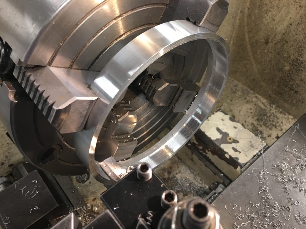
I test fit the air filter base and it’s a nice, snug fit onto the spacer.
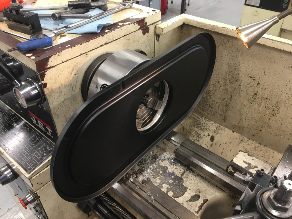
On the other side, you can see that the spacer doesn’t sit flush on the bottom of the air cleaner base. The problem is that the air cleaner base is a stamped steel part and there is a radius around the flange.
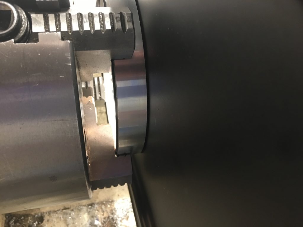
I machined a bevel on the inside corner of the spacer to allow space for the radius.
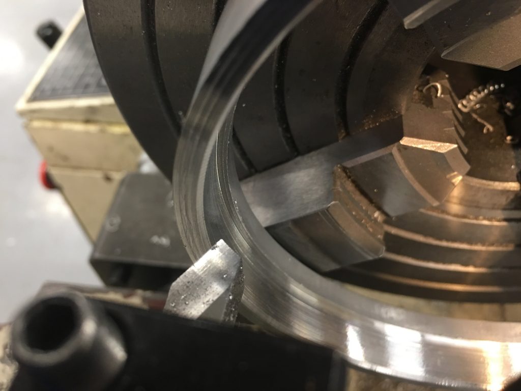
Now the spacer fits tight against the air cleaner base.
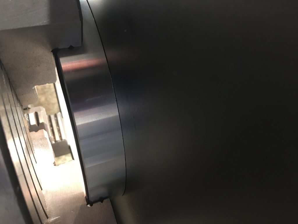
I installed the 1/4″-20 to 5/16″-18 adapter in the throttle body.
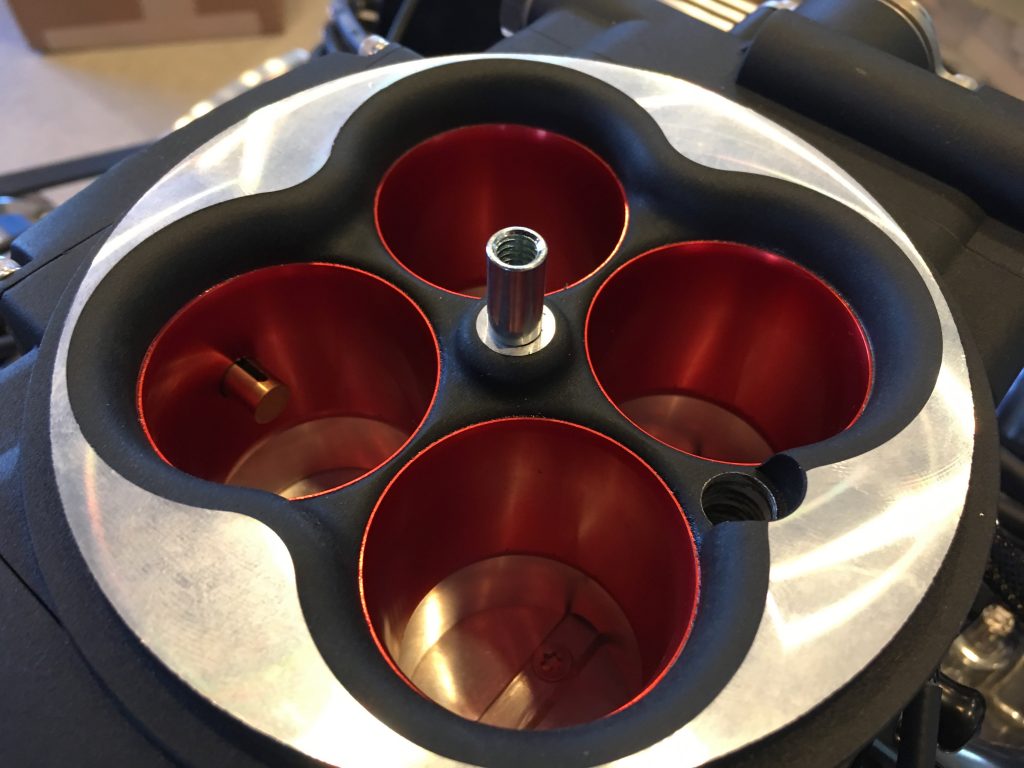
I had to cut down the shaft a bit so that it is the right length for the air cleaner plus spacer.
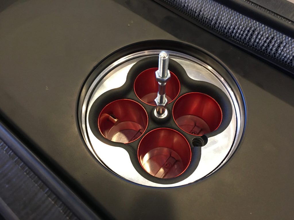
I did a final test fit of the air cleaner and everything looks great.
There’s now about 1/4″ of space above the throttle body which is plenty to prevent anything from touching and to clear the fittings that will thread onto the fuel connections you see here.
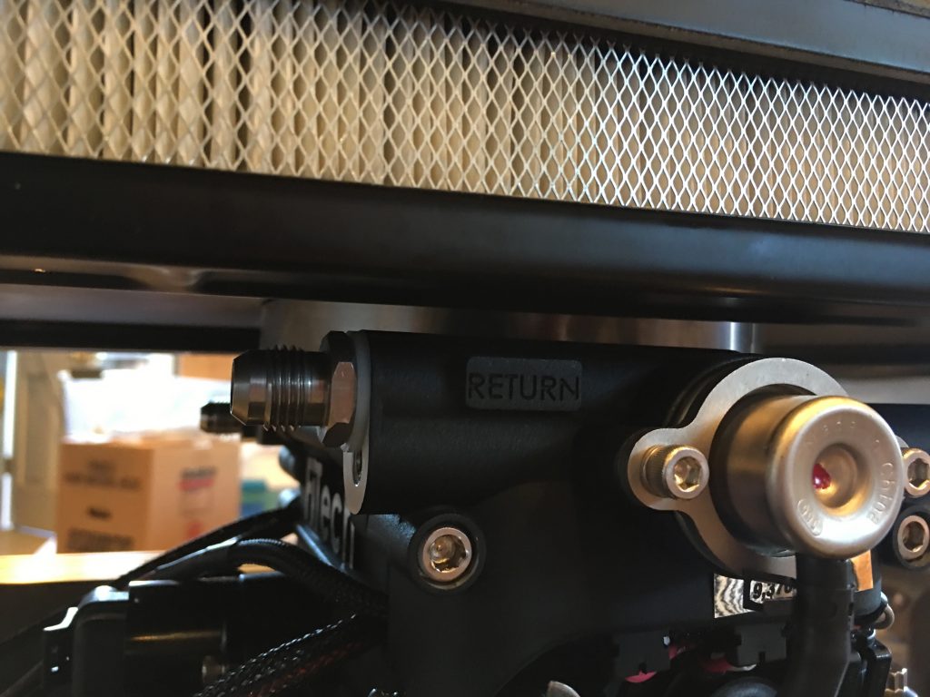
With the test fit complete, I used some black RTV to adhere the spacer to the air cleaner base. This seals out any leaks and means we don’t have to install the spacer separately. You can see here that the spacer also has an o-ring installed in the base so that we don’t need to use a gasket when installing the air cleaner.
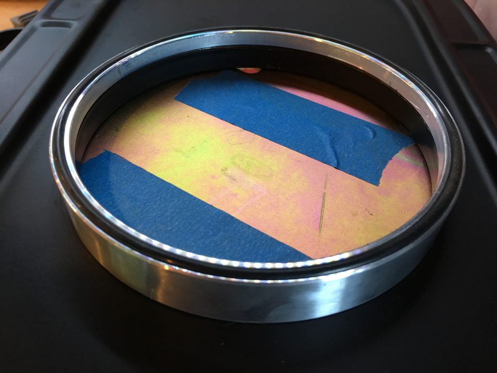
Our steering rack wasn’t centered before, so you could turn the wheels farther one direction than the other. You can compensate for this by using different thickness steering spacers on each side, but the right fix is to center the rack in the car.

My order from Breeze Automotive arrived today with their offset rack mounting kit which let’s you shift the rack from left to right and also lower it a bit which helps reduce bump steer.
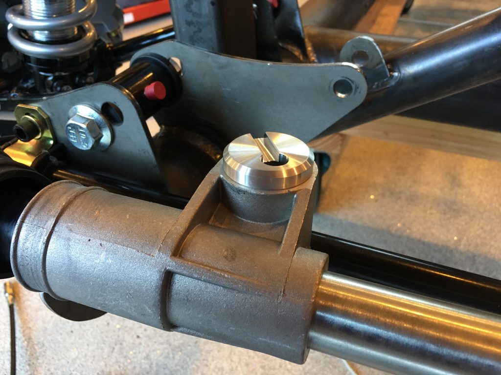
I installed the rack and some spacers and then adjusted the offset bushings until the rack was exactly centered in the chassis. One additional advantage of using the Breeze kit is that the steering rack is rigidly mounted which means it acts as a structural member of the chassis and increases its stiffness.
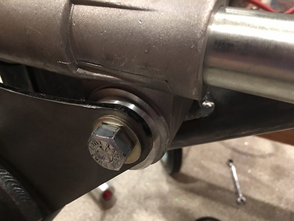
The rear hole on the passenger side needed to be elongated vertically since it wasn’t quite aligned with the front hole. It wasn’t really a problem with the polyurethane bushings since they could flex a little, but the rigid bushings require the holes to be aligned.
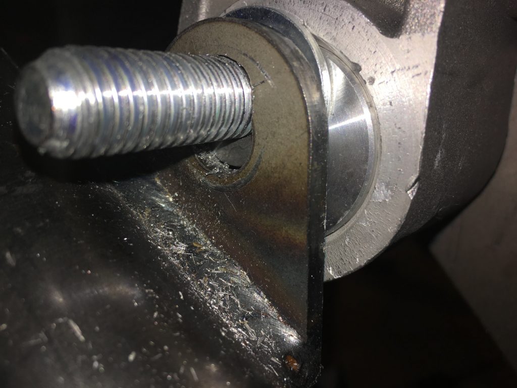
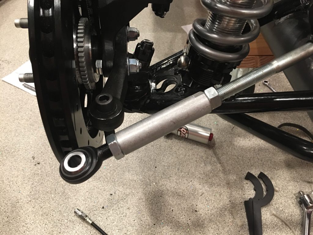
I also picked up a bump steer kit from Mike Forte. I threaded it in all the way on both sides and then loosened it until I had some adjustment available. With the steering rack centered and the wheel roughly aligned, it looks like the tie rod is nearly 2″ too long. I’ll confirm with Mike Forte before cutting them though.
Fit Air Cleaner

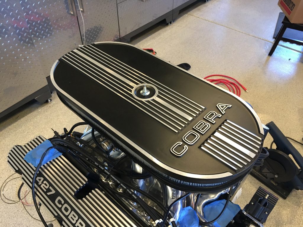
I test fit the air cleaner to make sure there weren’t any issues with it. This really dresses up the engine and the black and bare aluminum theme for the engine really looks sweet.

The air cleaner comes with a spacer that raises the base 1″. I assume it is optional, but the base hits the raised boss on the left side of the picture without it. Hopefully this doesn’t raise the air cleaner so high that it interferes with the body when installed in the car, but I can always cut it down a bit if necessary. This is a cheap piece of plastic, so I’ll probably upgrade to an aluminum one anyway.

I’m glad I did the test fit for another reason. I knew this air cleaner was held on by a center bolt that threads into the center of the throttle body and I assumed this was a standard size, but apparently that’s not true. The air cleaner came with a 1/4″-20 threaded rod that is 4″ long, but the FiTech unit is threaded for a 5/16″-18 rod. Summit Racing sells 1/4″-20 to 5/16″-18 adapters for $10-15, but you can buy an entire hold down kit that includes the adapter for $3…go figure.

Fit Fuel Injection System

Our FiTech Fuel Injection system showed up today. We had been planning on installing FiTech’s Go EFI 4 – 600 HP unit which should handle more horsepower than our engine should make. The next unit up is the Go EFI 4 – 600 HP – Power Adder which supports nitrous and superchargers. Even though we’re never planning on adding either of those, there are a couple of features of the PA unit which are appealing. First, the PA unit has an advanced mode on the handheld controller and can additionally be tuned with a laptop. This should give us a lot more flexibility to tune the engine for optimum performance. Second, the PA unit can control two separate radiator fans with different activation temperatures. With the amount of heat this engine will generate, I think this might be valuable.

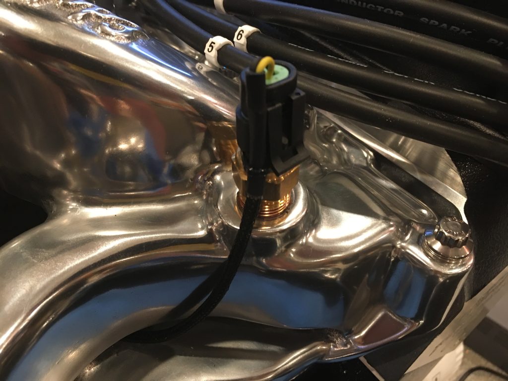
There are two ports at the front of the intake manifold that can hold the temperature sensor. This one only samples the coolant temperature of the coolant returning from the left bank of cylinders; the other samples both banks. I think I’ll end up with two sensors; one connected to the FiTech unit and the other connected to the dash gauge. I don’t know how much it matters which goes where, but I’m going to start with this configuration.

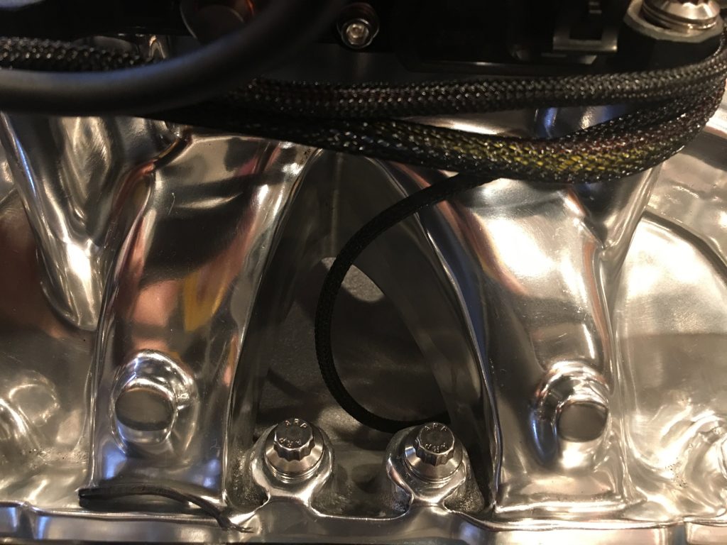
Since we have an air-gap intake manifold, I ran the wires under the intake runners and coolant passage. I also zip-tied the wire to the side of the sensor to eliminate strain where the wires enter the connector.

The wire comes out on the side between the runners for cylinders 3 and 4. All of the wire harnesses here will be secured with adel clamps once I have all of the wire routing figured out.

Replacing Headers

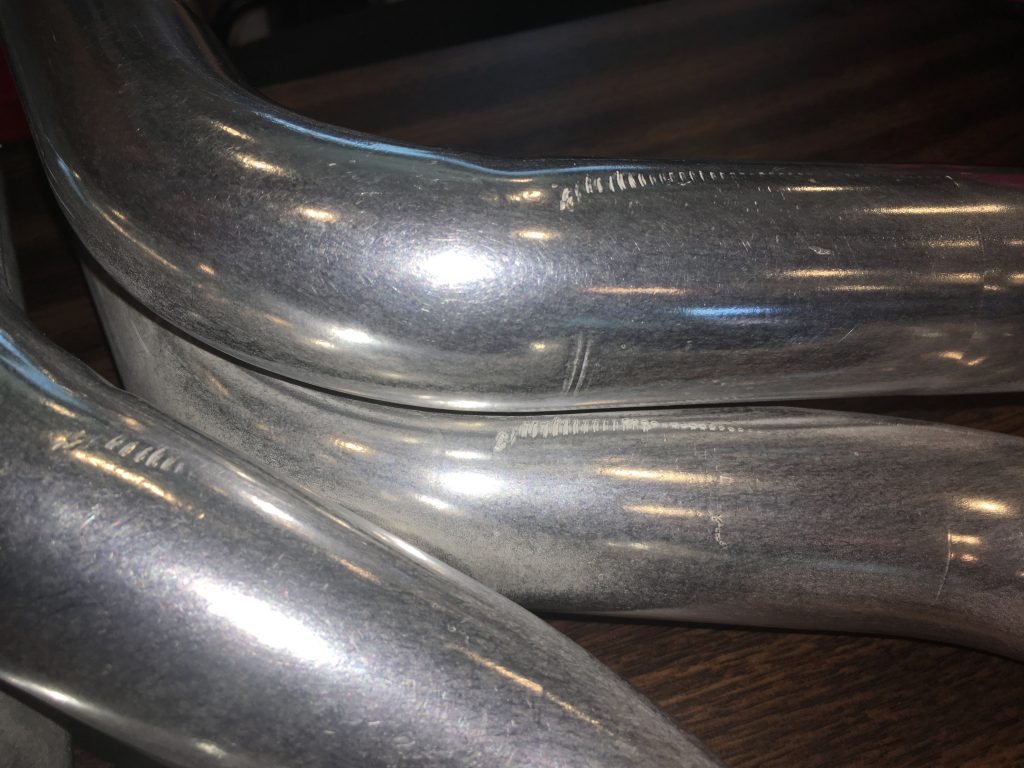
The 351W headers from Factory Five leave a lot to be desired.

  • They’re mild steel, so even with the ceramic coating on the outside, they will rust from the inside out.
  • They’re only 1.75″ pipes which is fine for a 351W, but really not enough for the 427.
  • They are four separate pipes all the way down to the square flange where they mate to the side pipes. With an EFI system, you have to install the O2 sensor after the four pipes merge so that you’re sampling one whole bank of cylinders. That means the O2 sensor would have to be installed on the side pipes where it will show.
  • They’re not mandrel bent, so there are fairly deep tooling marks all over the pipes which makes them look like shit.

After a bit of research, we’re going to go with a set of custom headers from GP Headers; they’re better in every way.

  • They’re made from 304 Stainless for maximum corrosion protection and long life.
  • We ordered them with 1 7/8″ pipes to allow the 427 to breathe a bit easier.
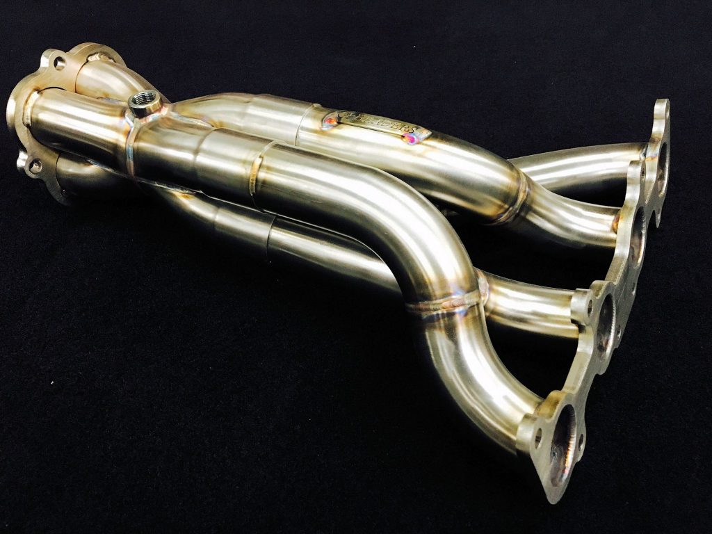
  • As you can see in the picture below (from a Coyote engine, but similar design), they have a double collector which allows the O2 sensor to be mounted inside the engine compartment.
  • They’re beautiful! Ours will additionally be ceramic coated for heat and appearance reasons.

These are substantially more money than the FFR versions (nearly 3x the cost), but I think they’re absolutely worth it.

Spark Plug Wires and Steering Linkage

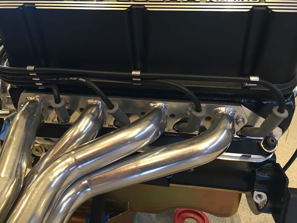
I temporarily fit the headers so that I could route the spark plug wires. I’m using the MSD multi-angle boot spark plug wires so that I can adjust the boots for the best clearance. I’ll do the final tweaking of the boot angles and wire position once the distributor is installed and all of the wires are cut to length.

I’m using some billet aluminum wire supports from Billet Specialties.

They replace the valve cover bolts and are a solid piece (unlike many of the cheaper wire supports). They’re sold in packs of two with between 1-4 spots for wires. I needed the following:

  • 3x 4 position
  • 1x 3 position
  • 2x 2 position
  • 1x 1 position

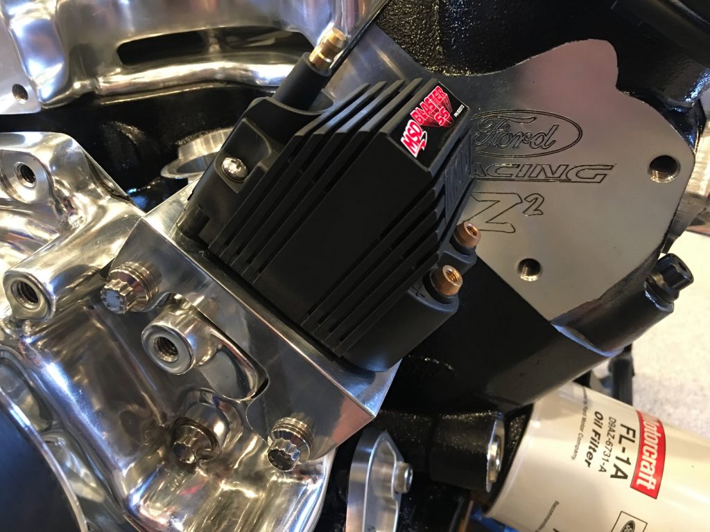
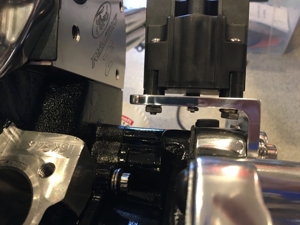
I also further trimmed the ignition coil bracket I made and polished it up before mounting it to the water pump. I needed to order some custom length bolts to mount this since the old bolts were too short.

There’s plenty of clearance between the bolts that attach the coil and the top of the water pump. The right most bolt looks like it’s not engaged sufficiently, but the stud is flush with the bottom of the nut. Given the low load on these, that is sufficient.

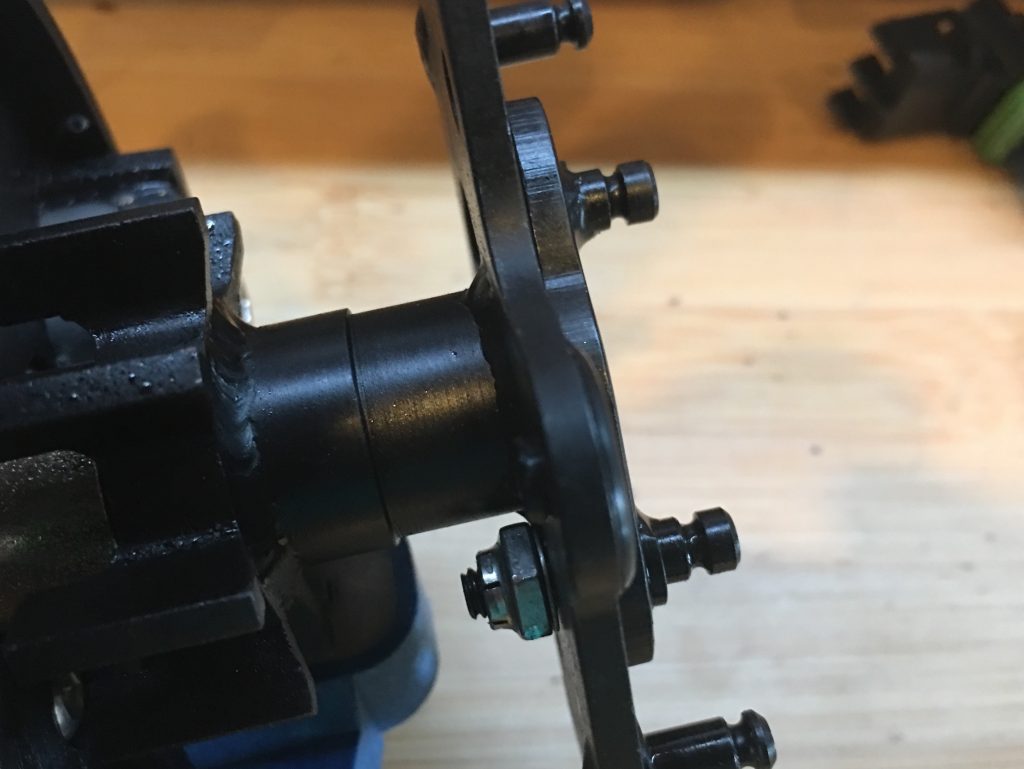
I pulled off the F panel on the left side and welded the brackets on securely. I think the steering linkage is installed for the last time before we drive the car.

Steering Linkage, Chassis Mods and Timing Pointer

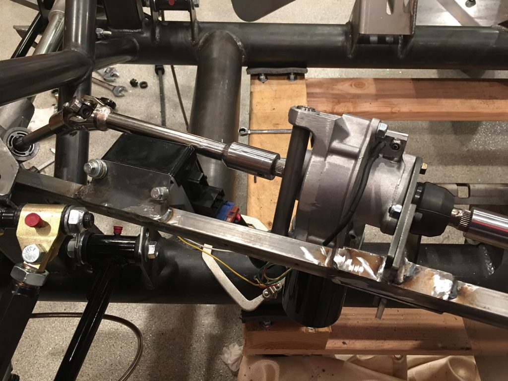
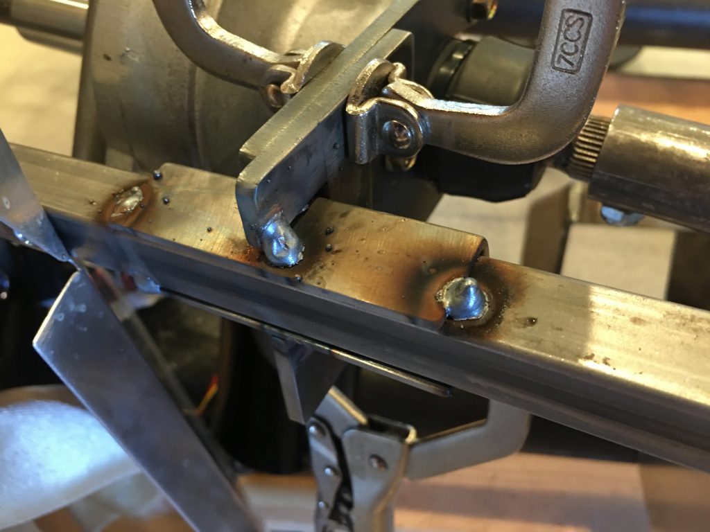
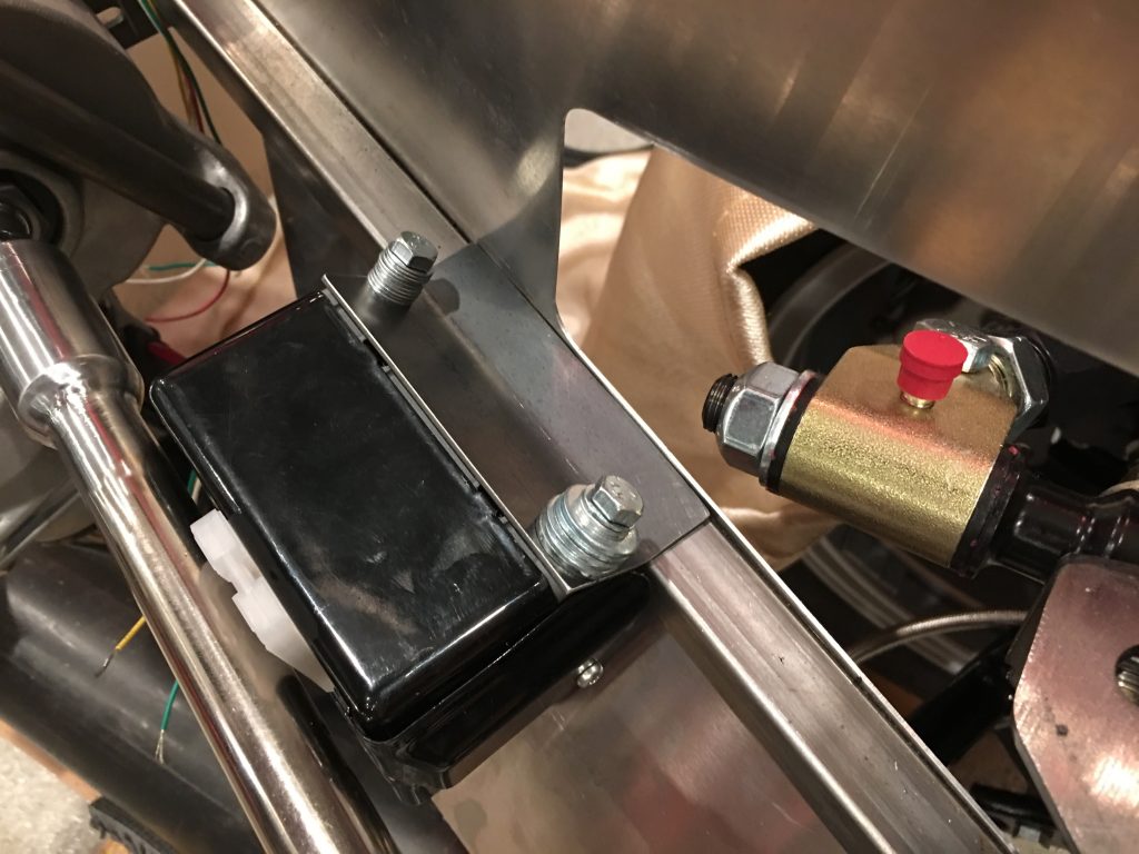
I installed the EPS brackets and tacked the two pieces of the bracket together and tacked it to the chassis. I’ll finish welding this after pulling the steering linkage off and unscrewing the aluminum F panel.

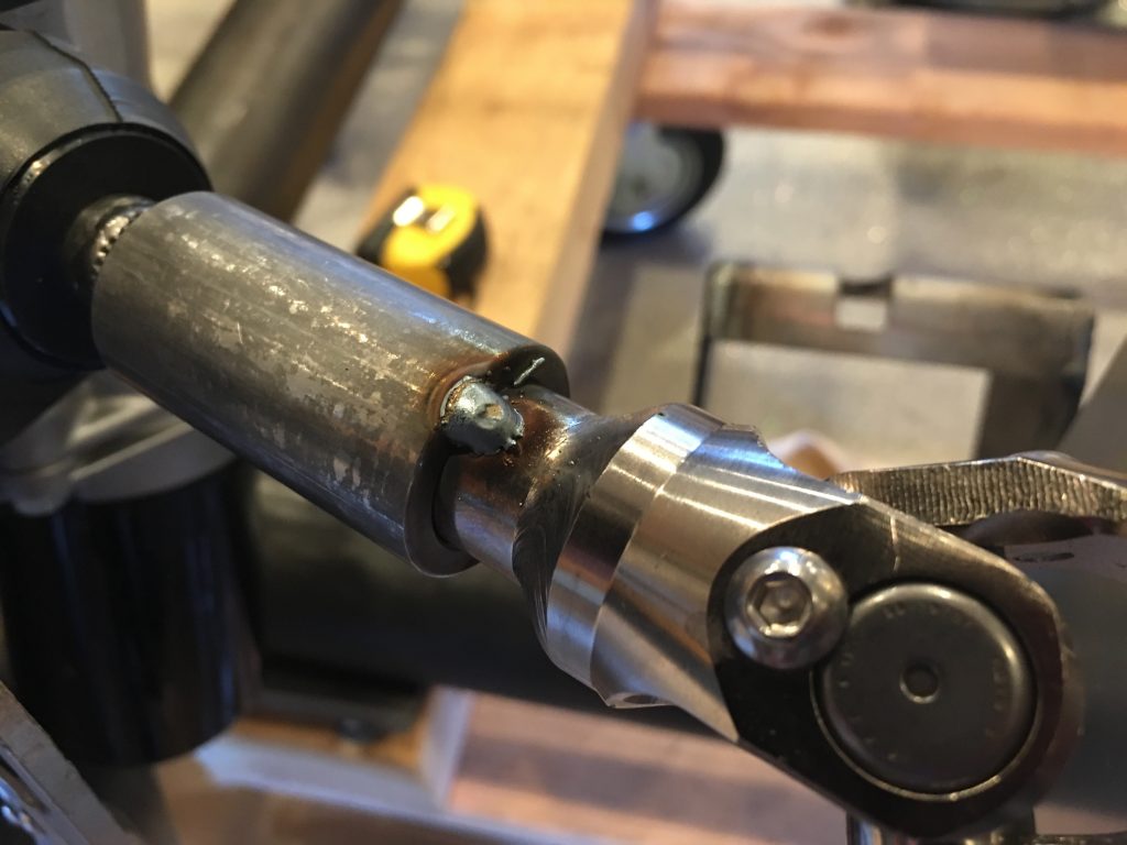
With the steering linking all bolted into its final location, I tacked the upper coupler to the steering shaft.

I also tacked the lower coupler.

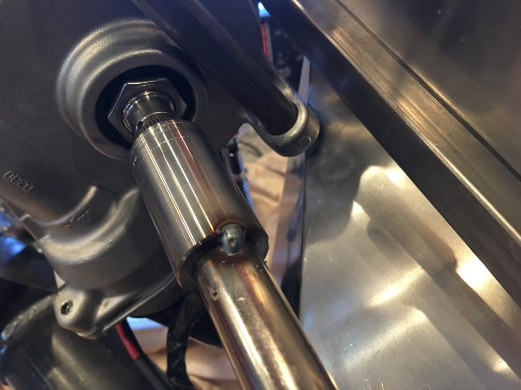
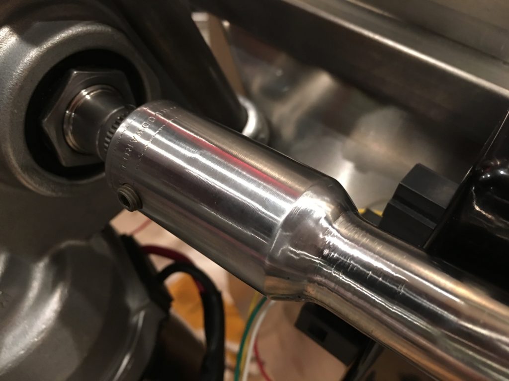
I then TIG welded the couplers all the way around and ground everything smooth. Here’s the upper coupler.

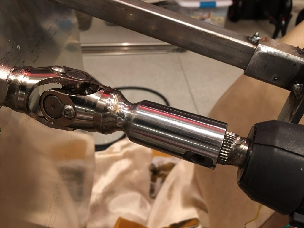
And here’s the lower coupler. I may have these chromed after the chassis comes apart for finishing.

While I was at the TechShop, I fabbed up a piece of 16ga steel to attach the EPS controller to the chassis. The bolts are metric, so the only ones I had on hand were too long. I’ll pick up the right bolts before bolting this in for good.

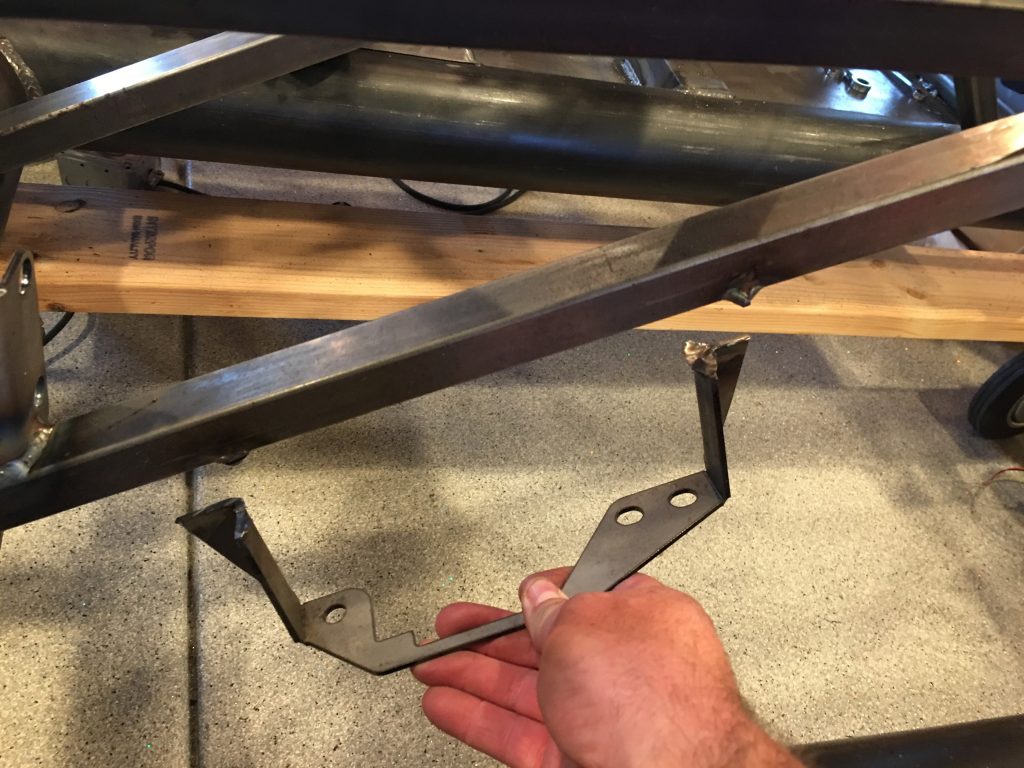
Since I’m relocating the parking brake, I cut off the bracket that holds the handle. I’ll have to fab up a bracket once I figure out the new location.

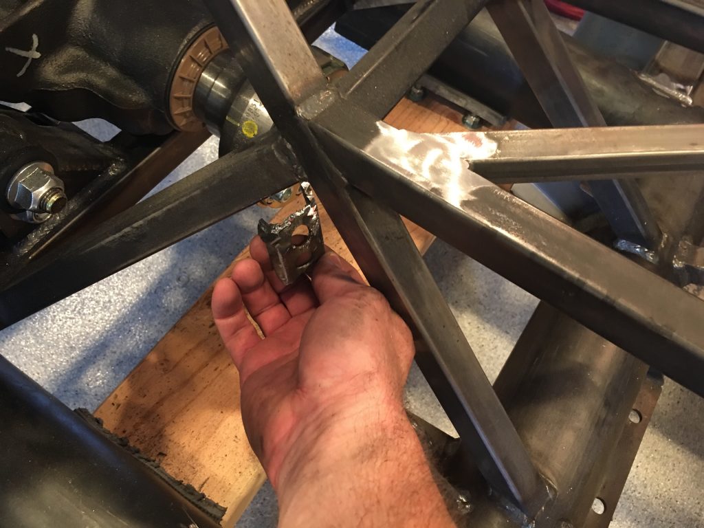
I also cut off the bracket that hold the parking brake cables. I really wish I had cut this off before installing the differential; it was a real challenge cutting this off while working around it.

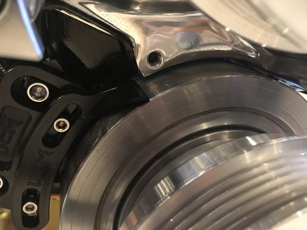
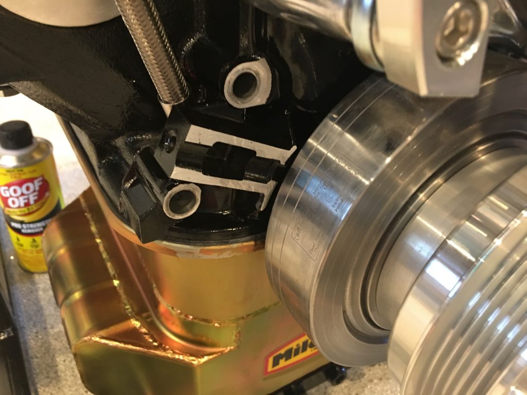
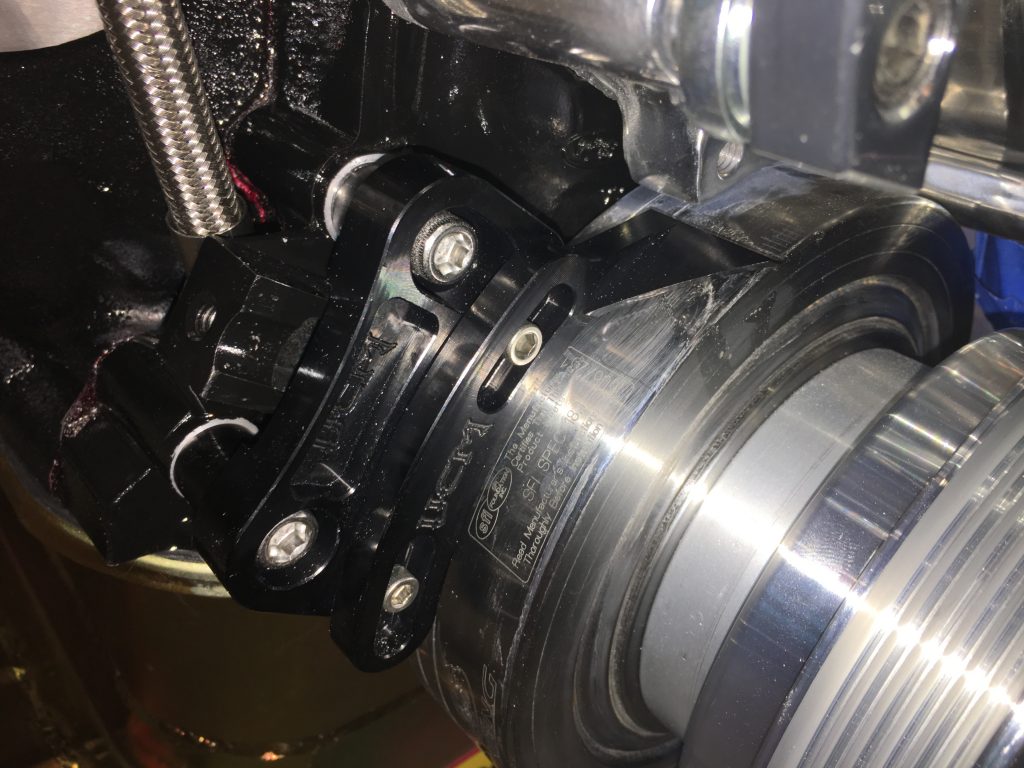
I originally purchased a timing pointer that mounts at the 2 o’clock position, but it turns out that that would be pretty hard to see since we’re using a water pump with a driver side inlet. I replaced that with one that mounts at the 11 o’clock position, but it interferes with a bracket on the Ford timing cover. Ford confirmed that it’s unnecessary, so I cut it off with a cutoff wheel.

After touching up the paint, I installed the pointer and aligned it with the 0º mark.