More Chassis Rivnuts

Astro Pneumatic was nice enough to send me replacement mandrels even though they consider them consumables. I went ahead and ordered a couple of extras since I knew I had hundreds more rivnuts to install. I managed to make it through virtually every remaining rivnut on the chassis. There are only a handful left that I can’t reach with the Astro tool.

I broke one of the replacement mandrels by over-torquing the tool slightly. After that, I only used the tool with a 1/4″ drive socket wrench instead of a cordless drill. By doing that, I could pretty easily stop before the torque got too high. After that, I installed 200+ rivnuts without breaking a mandrel (more than the previous two mandrels combined).

Wiring Connectors and Rear Brake Line

My order of Weather Pack connectors showed up, so I installed the remaining ones that were missing. For the headlights, I also fabricated short jumper cables to the plug that attaches to the back of the bulb. When I switch to LED bulbs, they might have a different connector on the back, so it will be trivial to fabricate a different jumper if necessary.

I also got started on the rear brake line. This line runs from the forward side of the pilot’s footbox, along the upper 3/4″ tubing to the x-frame and down to the main 4″ chassis tubing. There will be a union there to the piece of tubing that runs the rest of the way to the rear tee.

Chassis Rivnuts & Front End Wiring

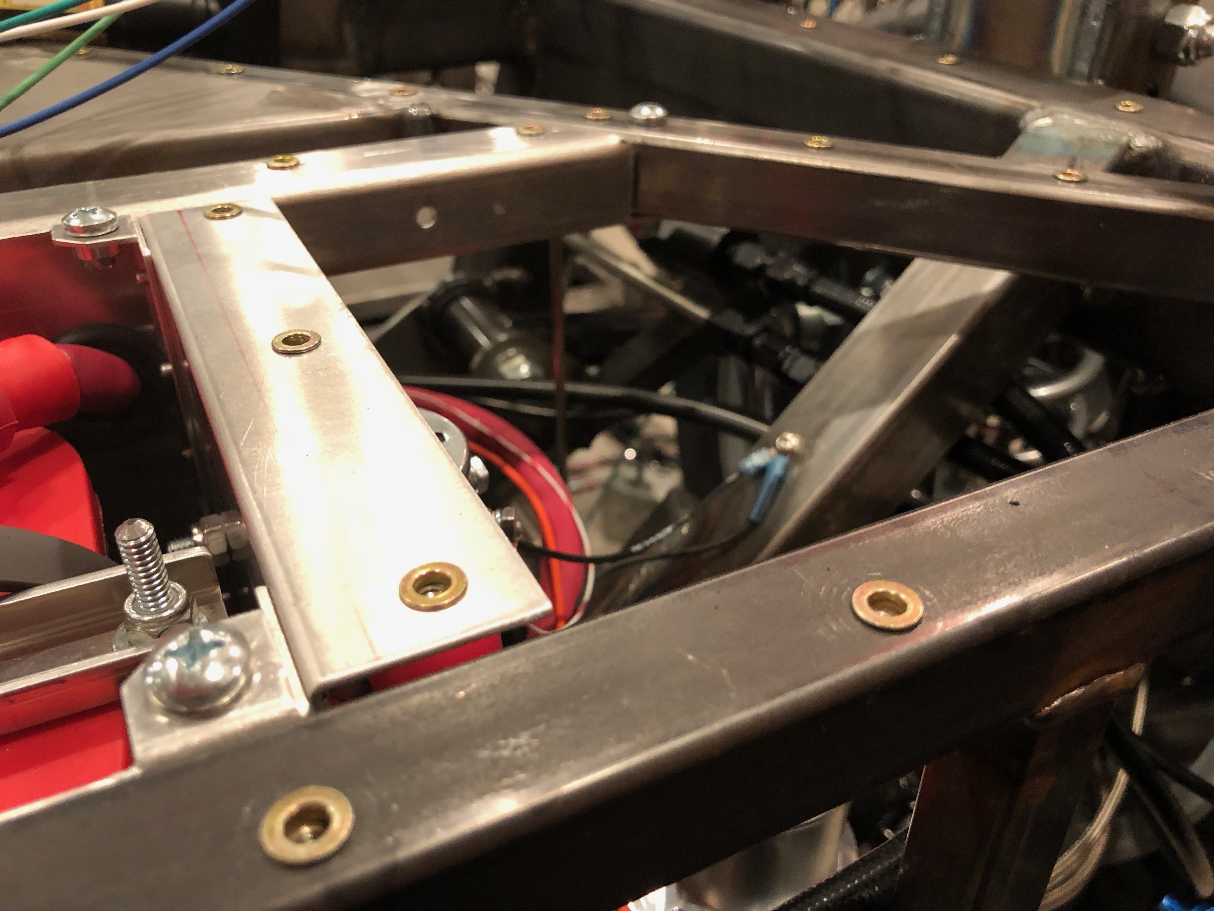
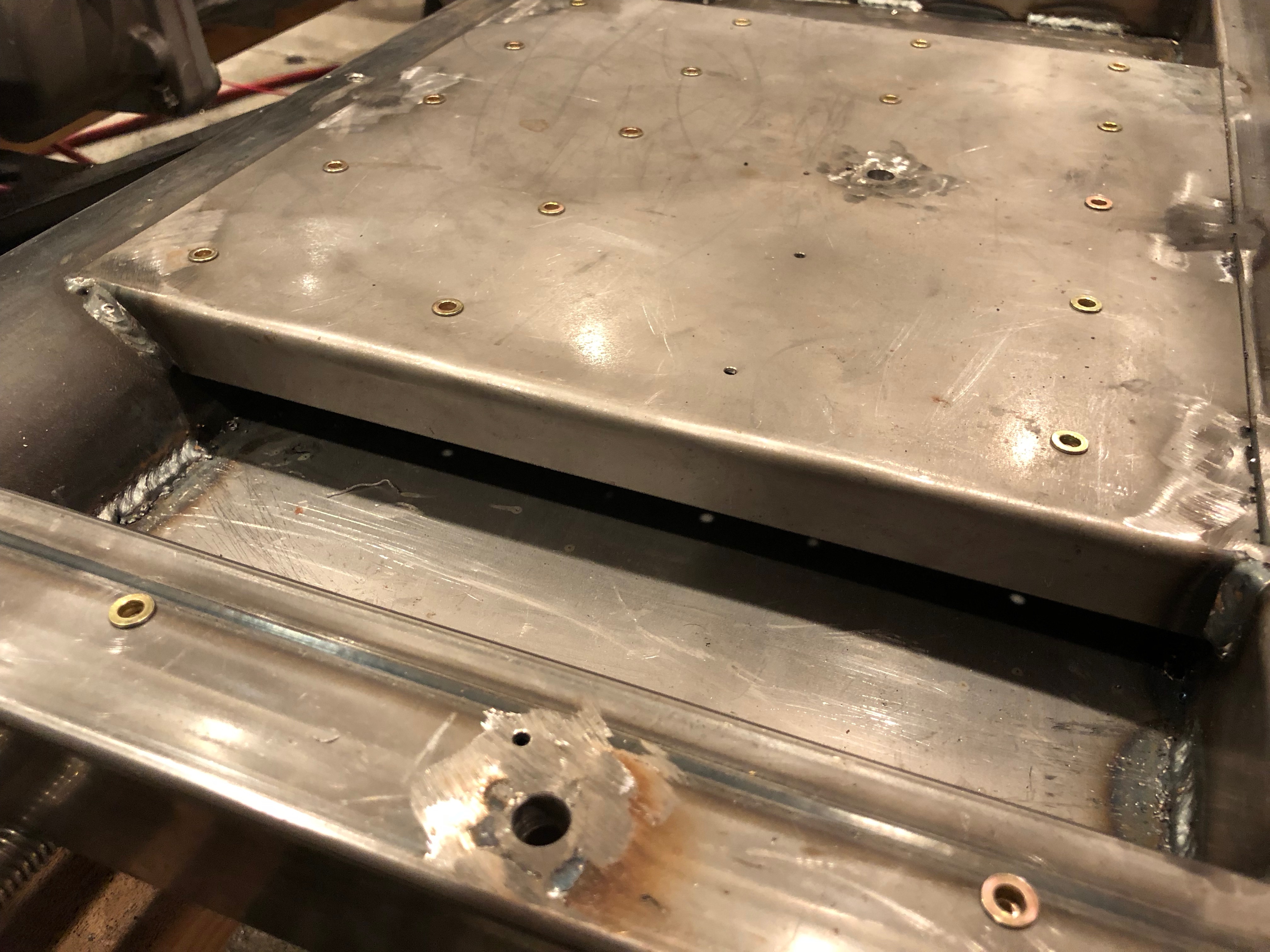
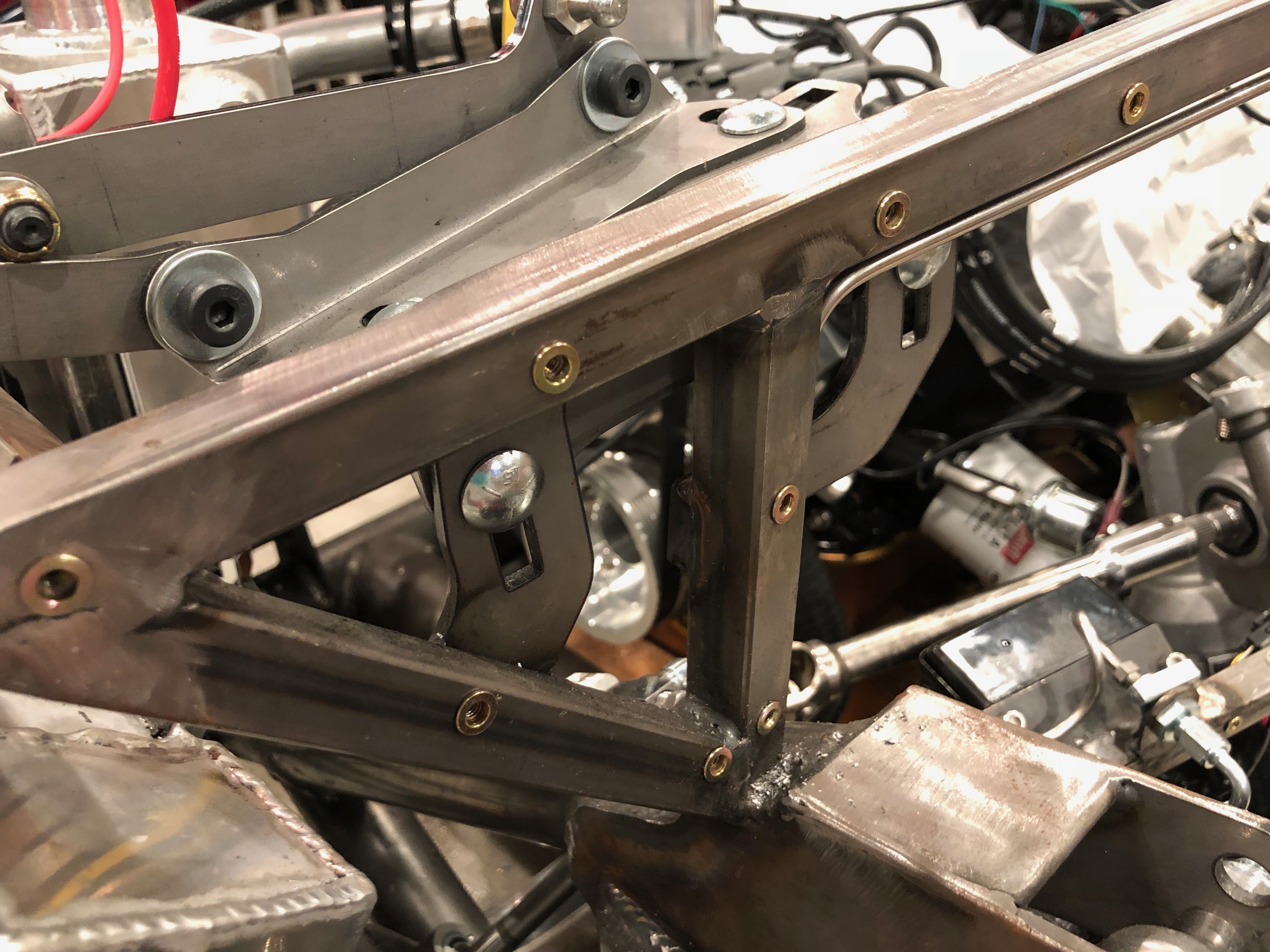
I knocked out a bunch more of the chassis rivnuts that will secure the aluminum panels. Unfortunately, the 8-32 mandrel broke after a couple hundred, so I had to stop. Astro Pneumatic has a 1 year warranty and claims they will replace any component that fails under normal use, so we’ll see if they cover this. In the mean time, I have plenty of other things to work on.

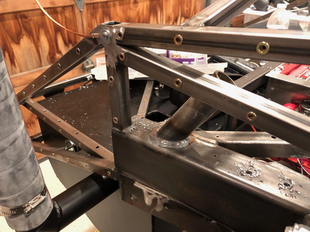
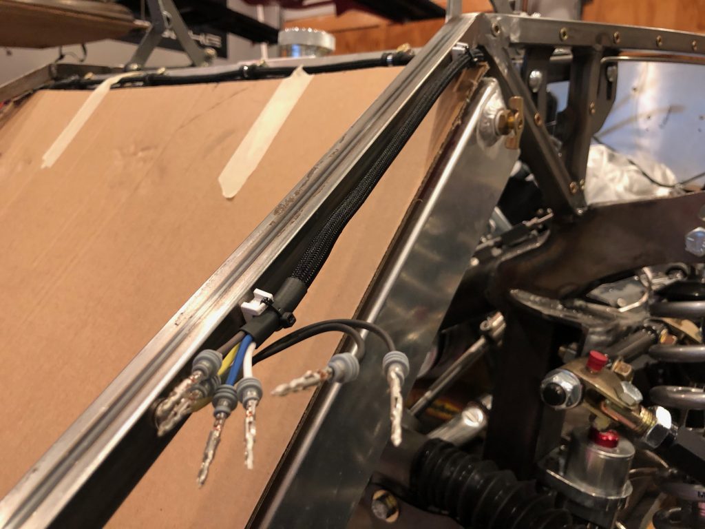
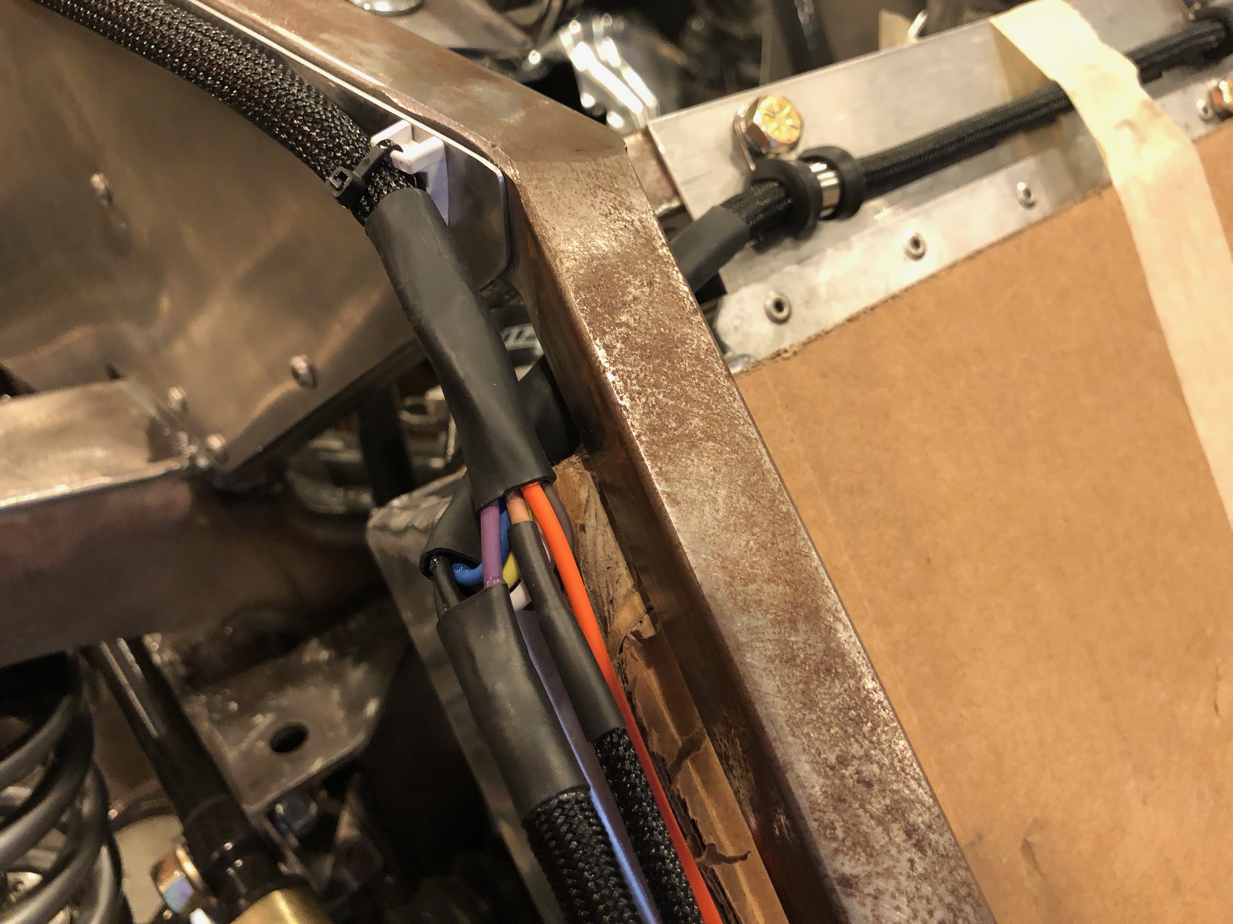
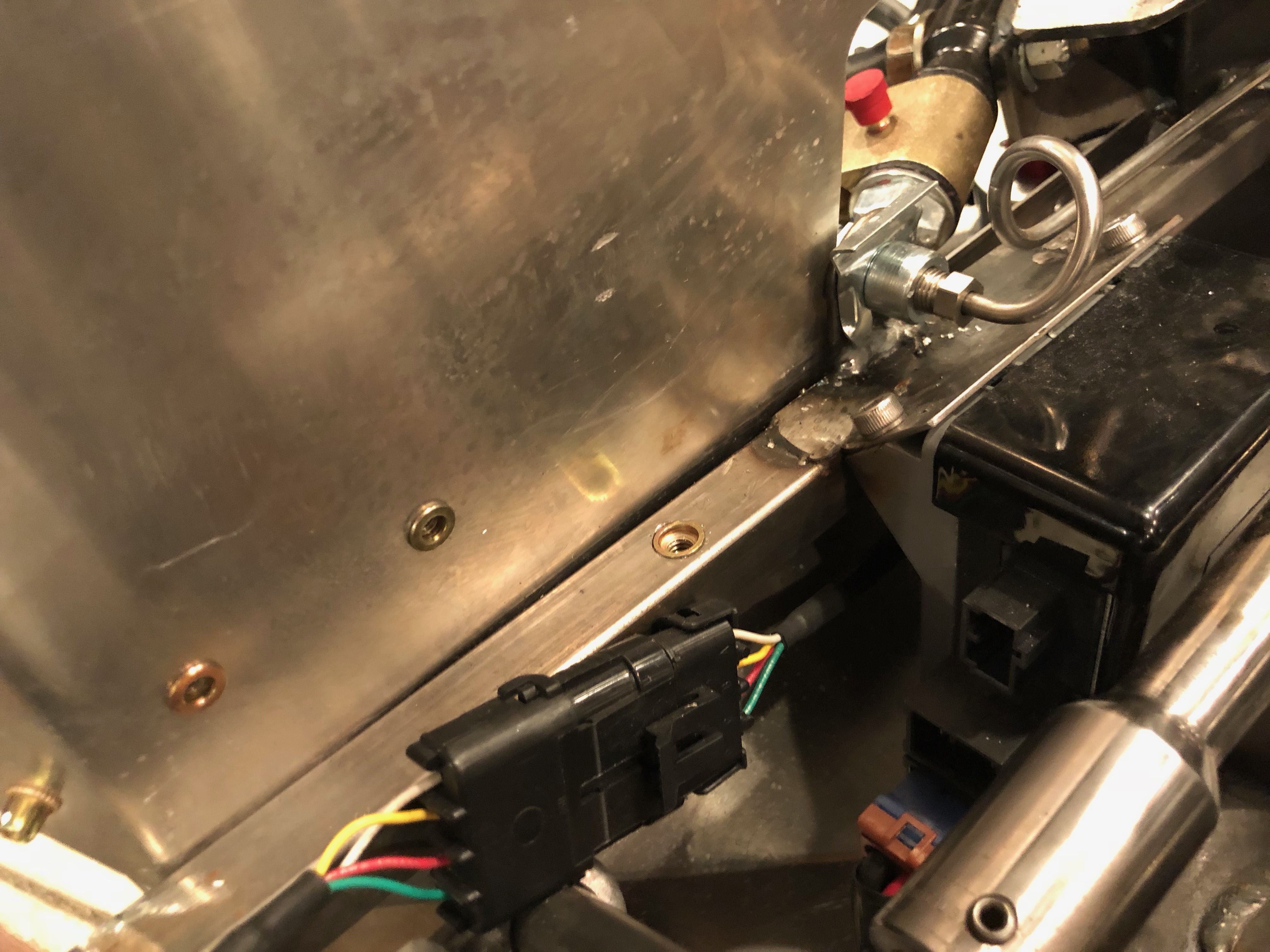
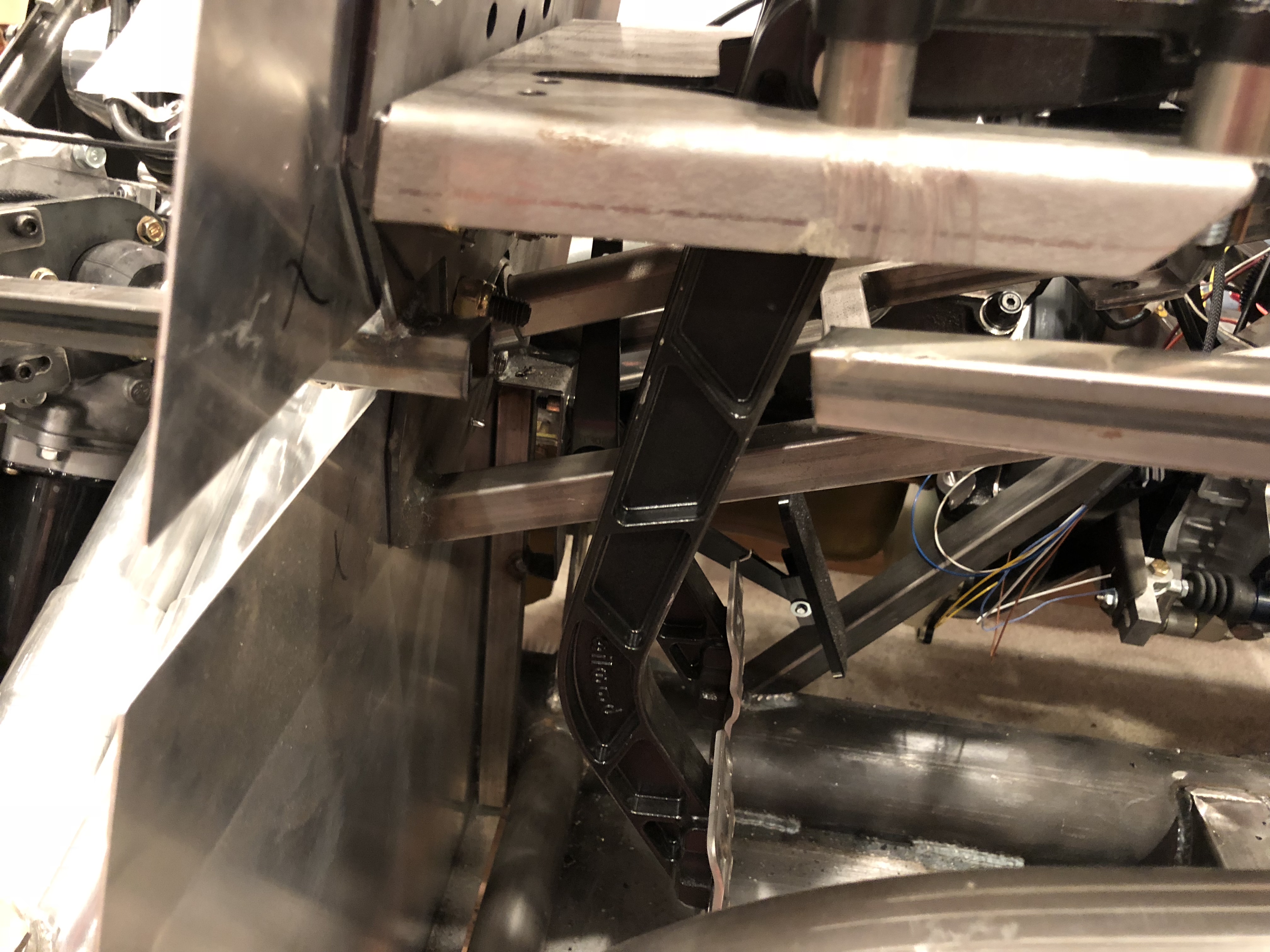
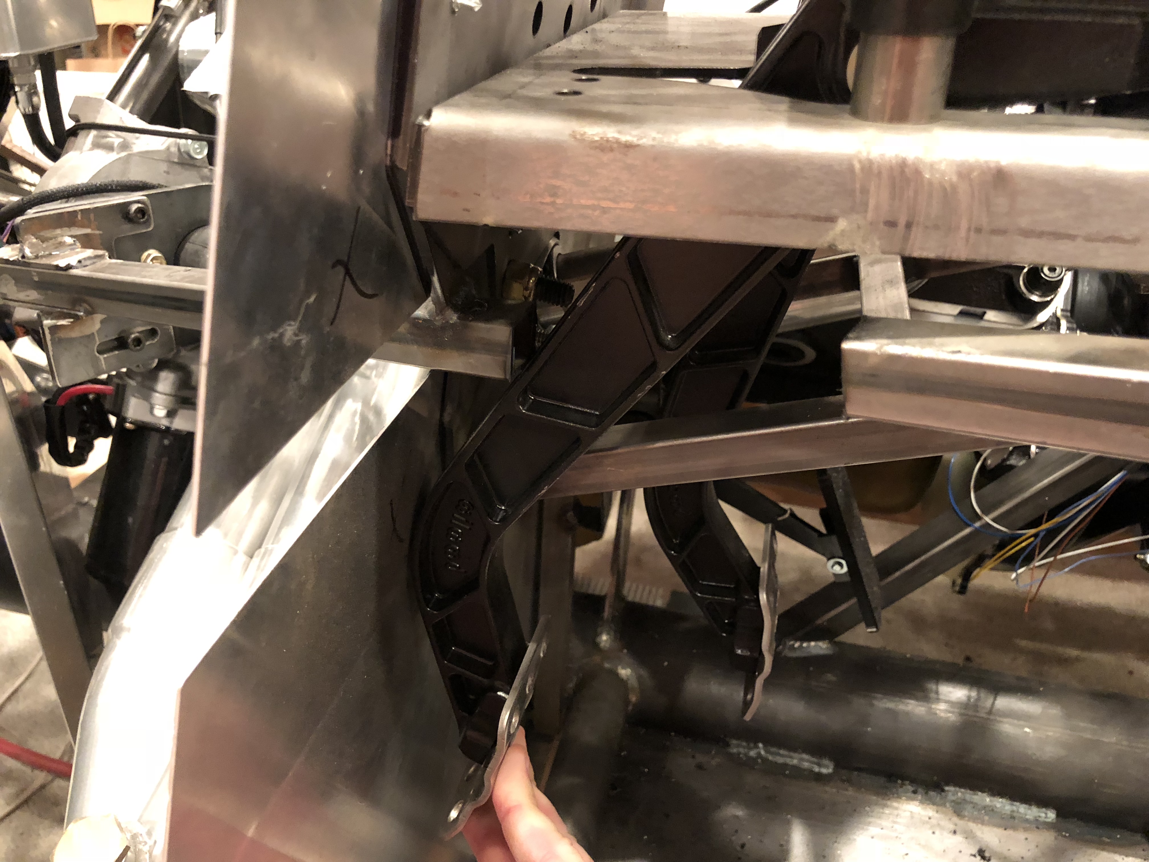
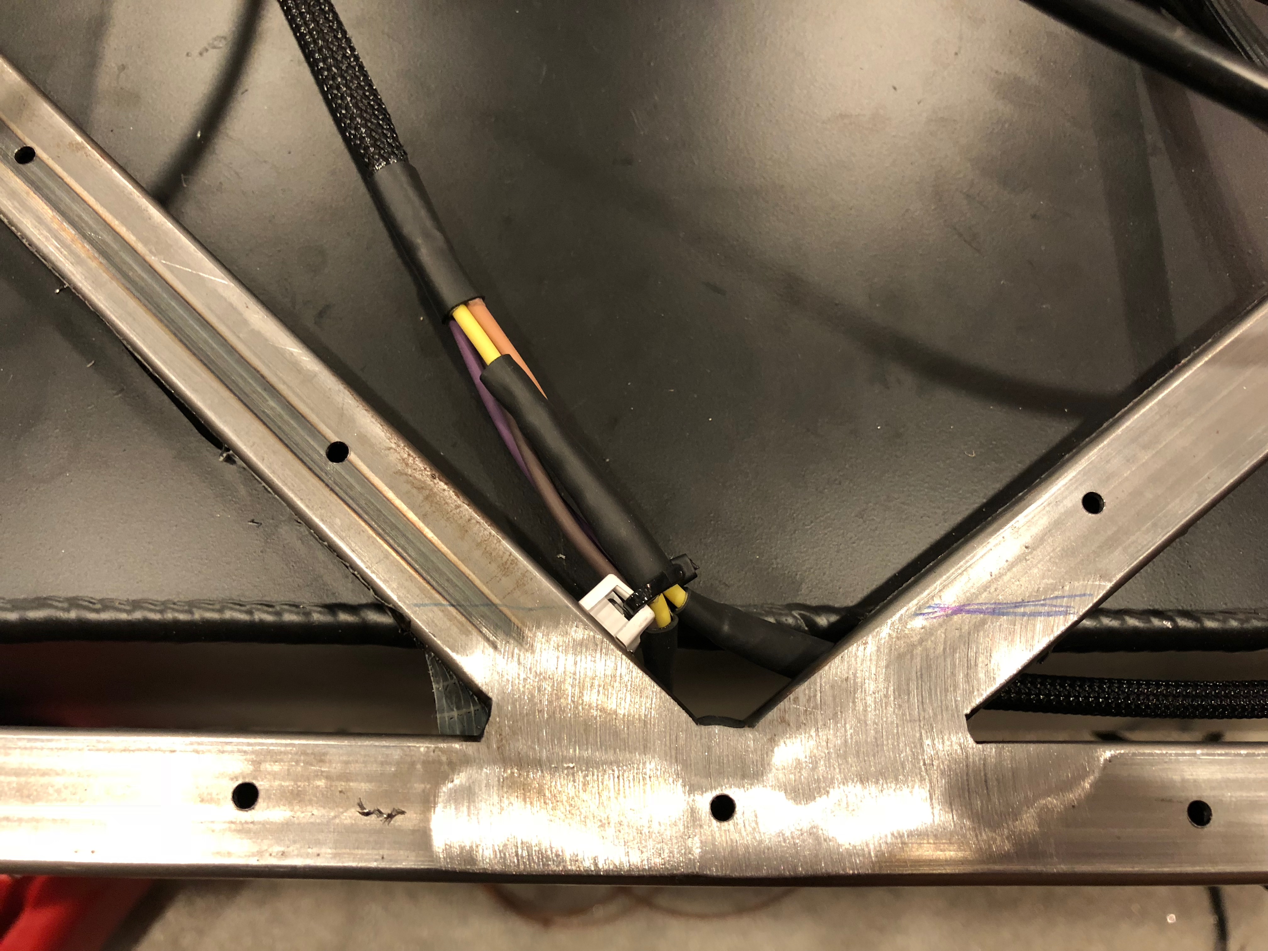
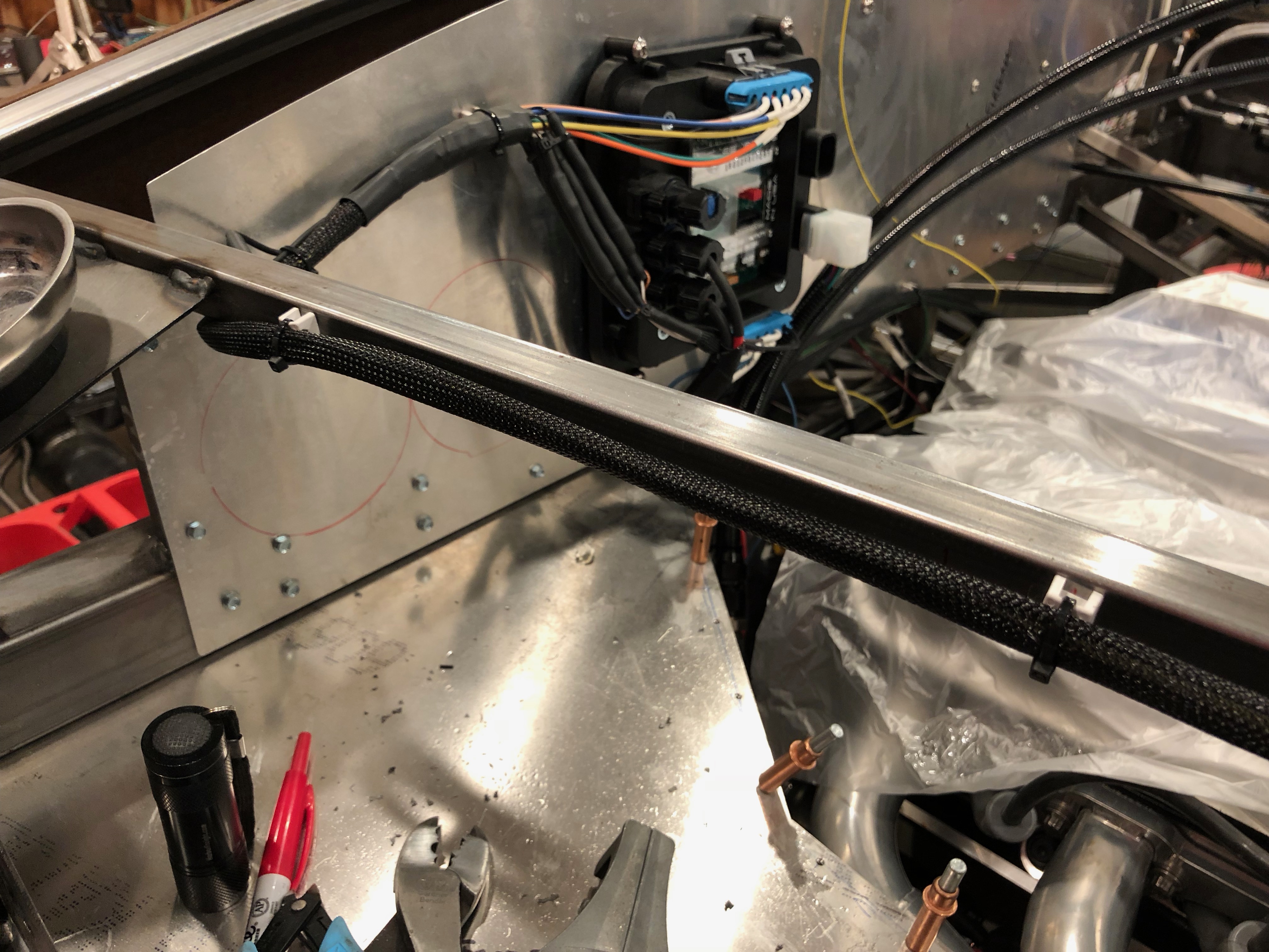
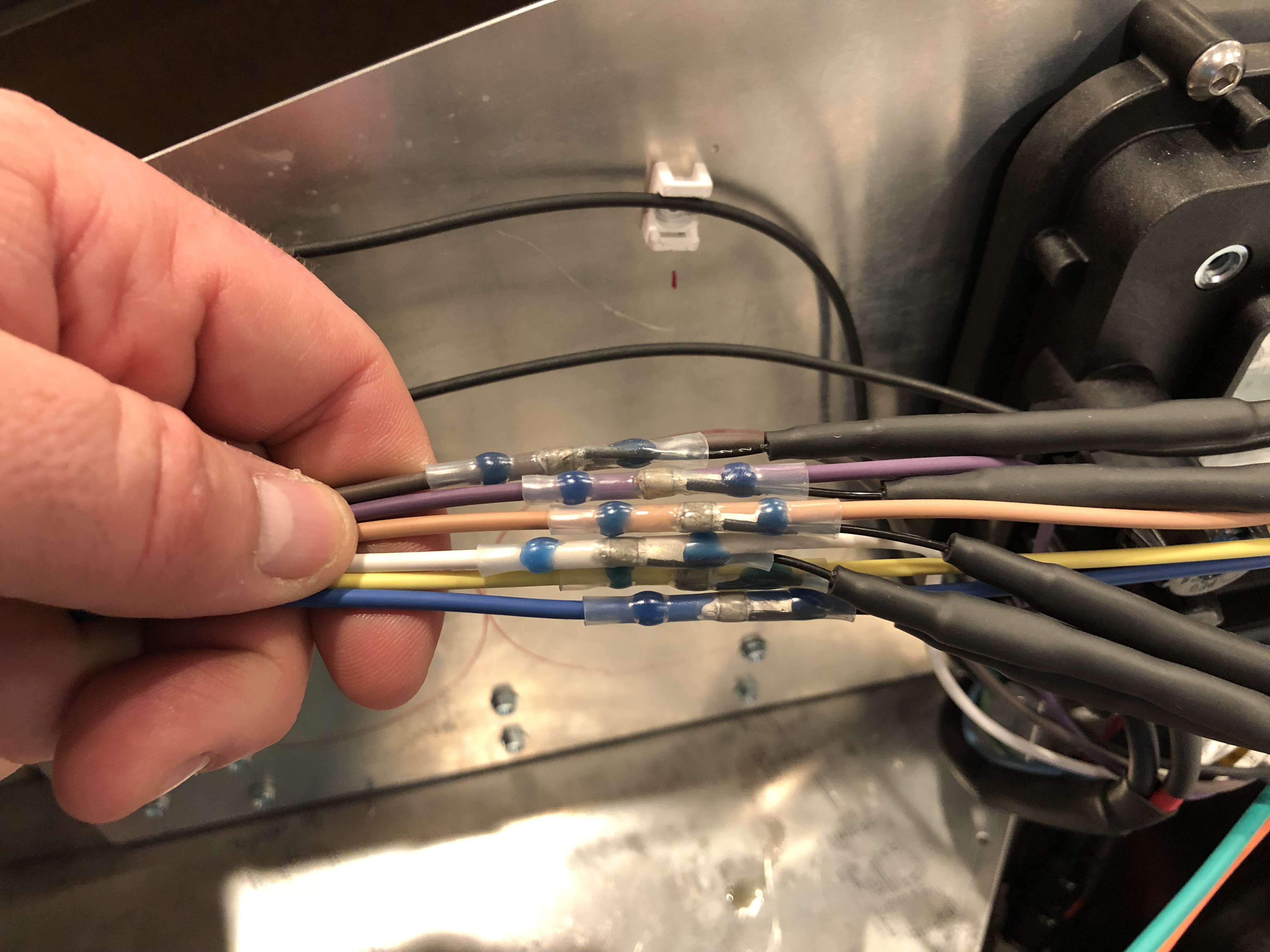
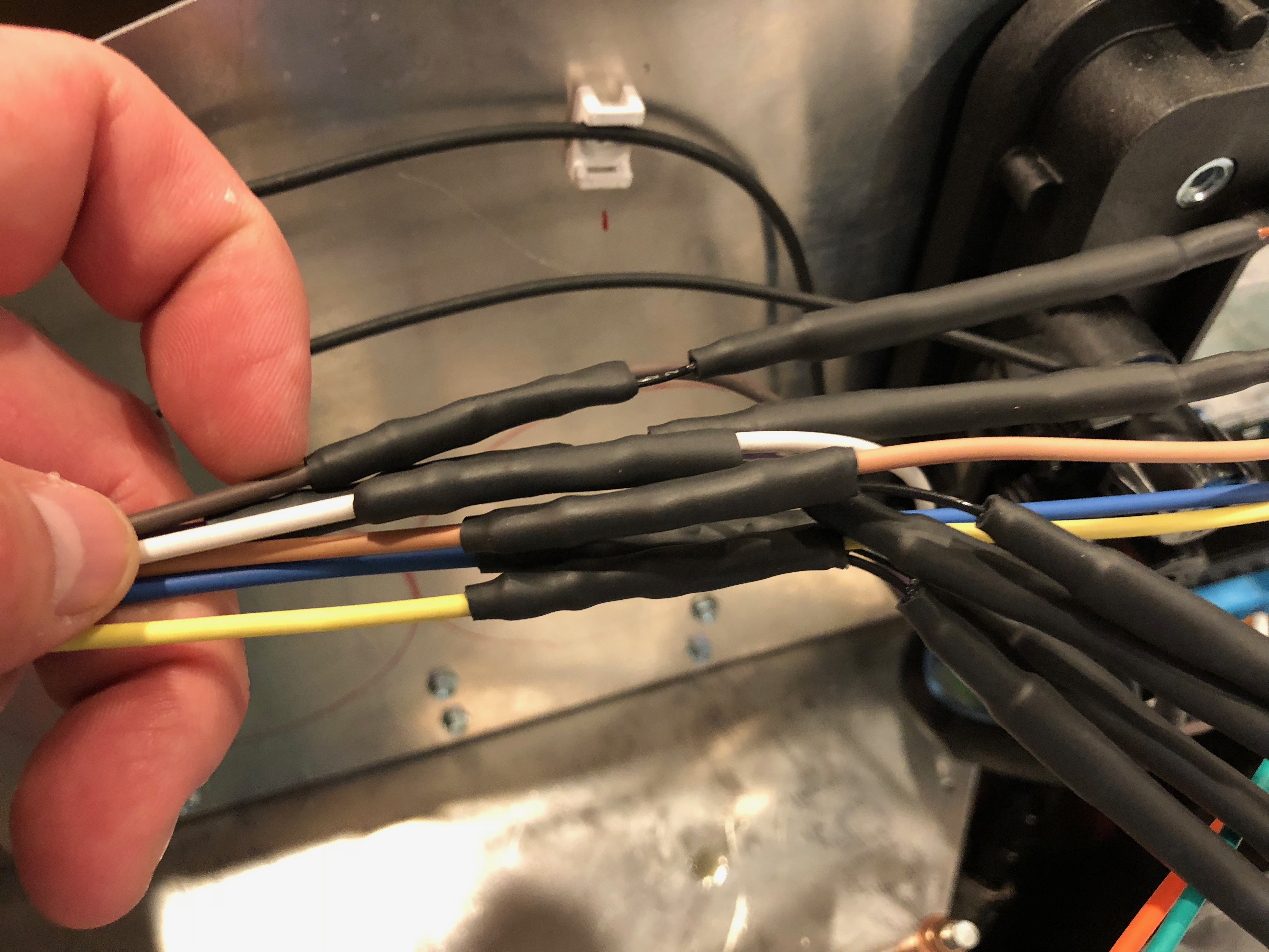
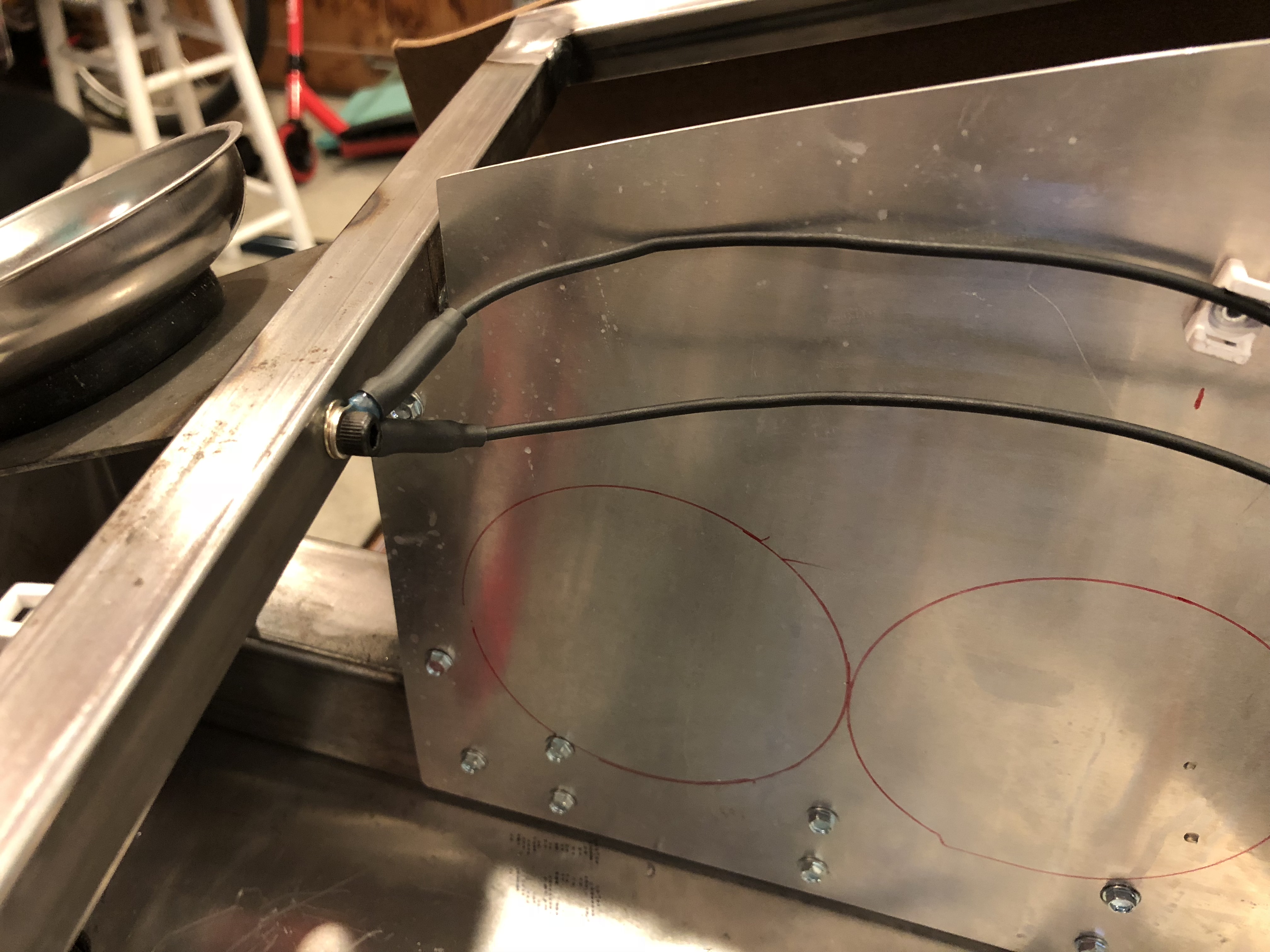
Three of the wires in the front chassis wiring harness (parking lights, low beams and high beams) need to be split and run to both the front left corner and front right corner. I stripped the insulation and used a few solder sleeves to splice into the wires. The bundle for the front left corner (which also includes the left turn signal) cuts under the chassis tubing and runs across the top edge of the radiator, secured by some adel clamps.

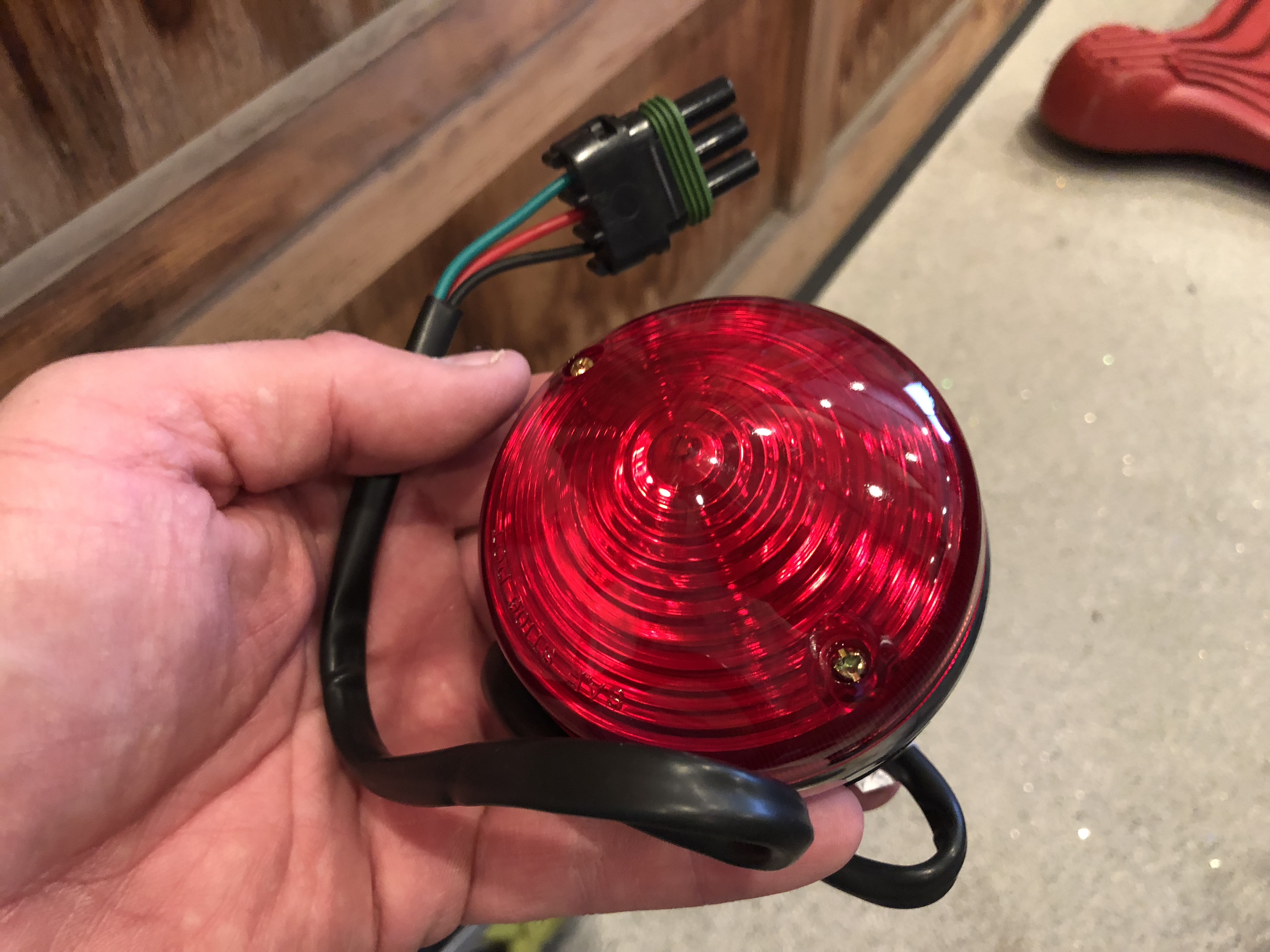
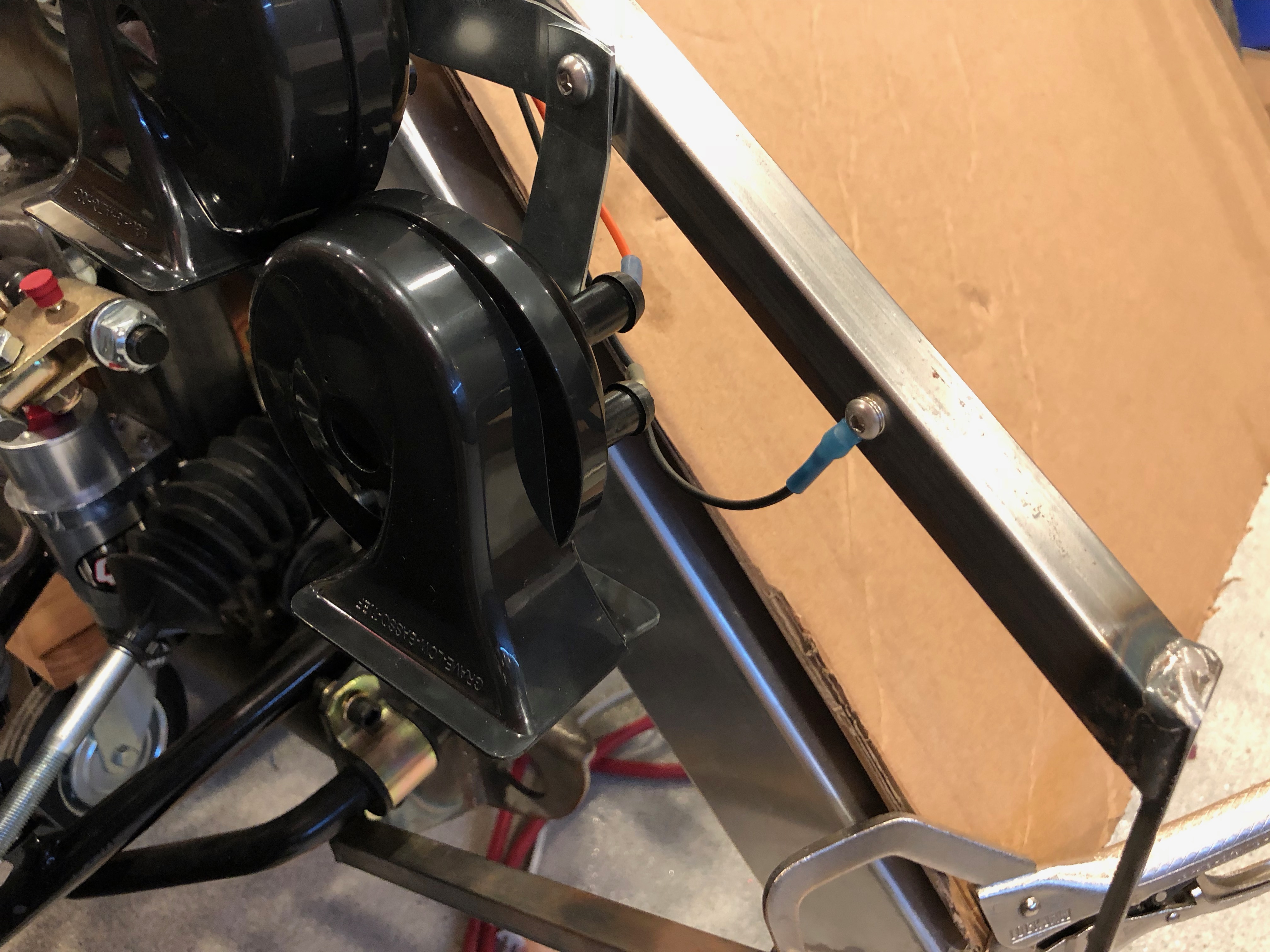
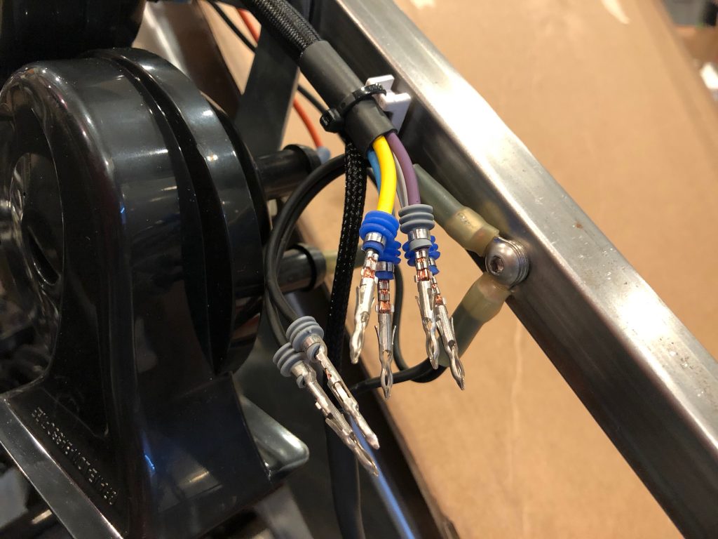
I ran out of three-conductor Weather Pack connectors, so I just terminated these with the appropriate plugs and seals. There will be two connectors here: one connector for the headlights with a ground wire, low and high beam wires, and another connector for the indicator light with a ground wire, parking light, and right turn signal.

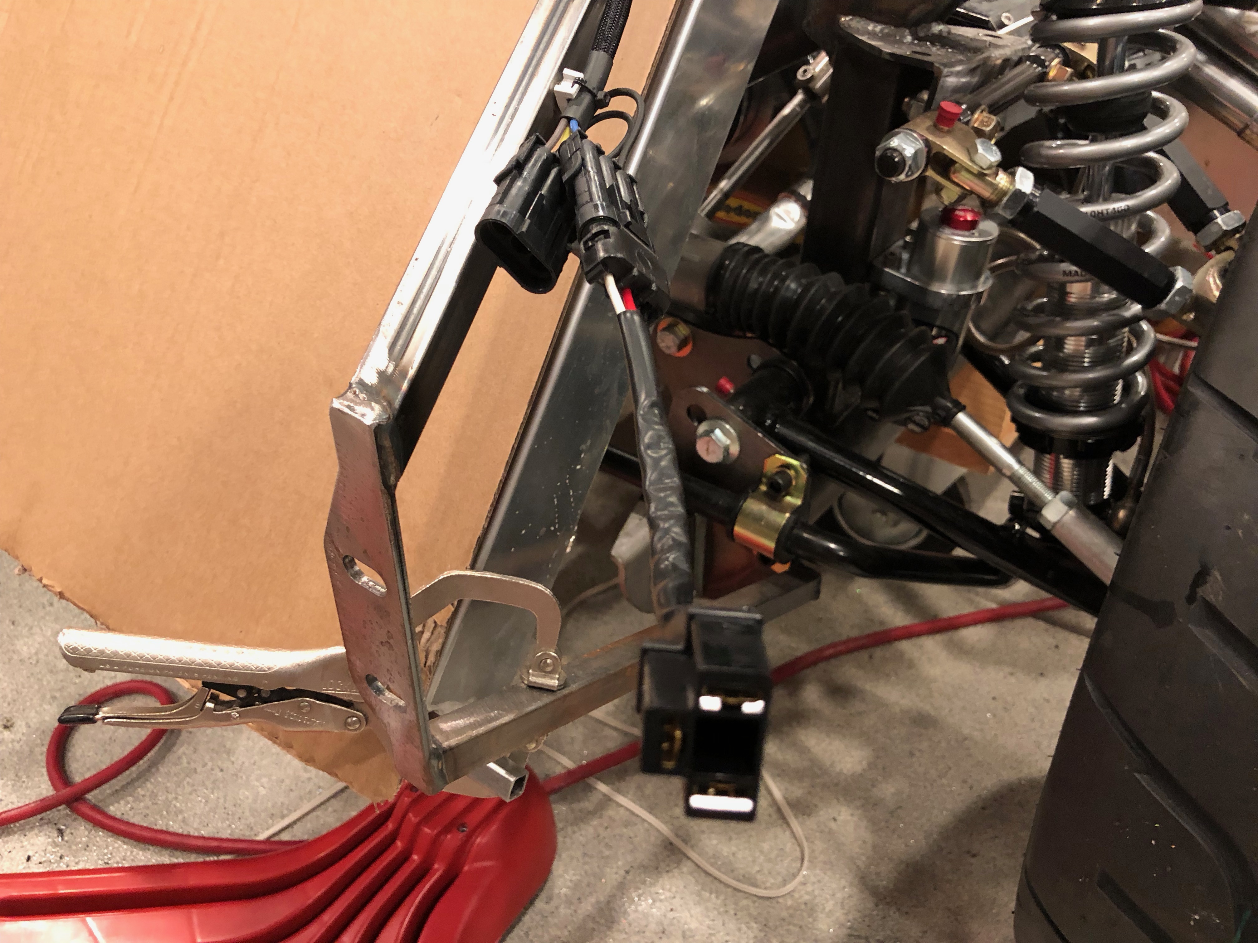
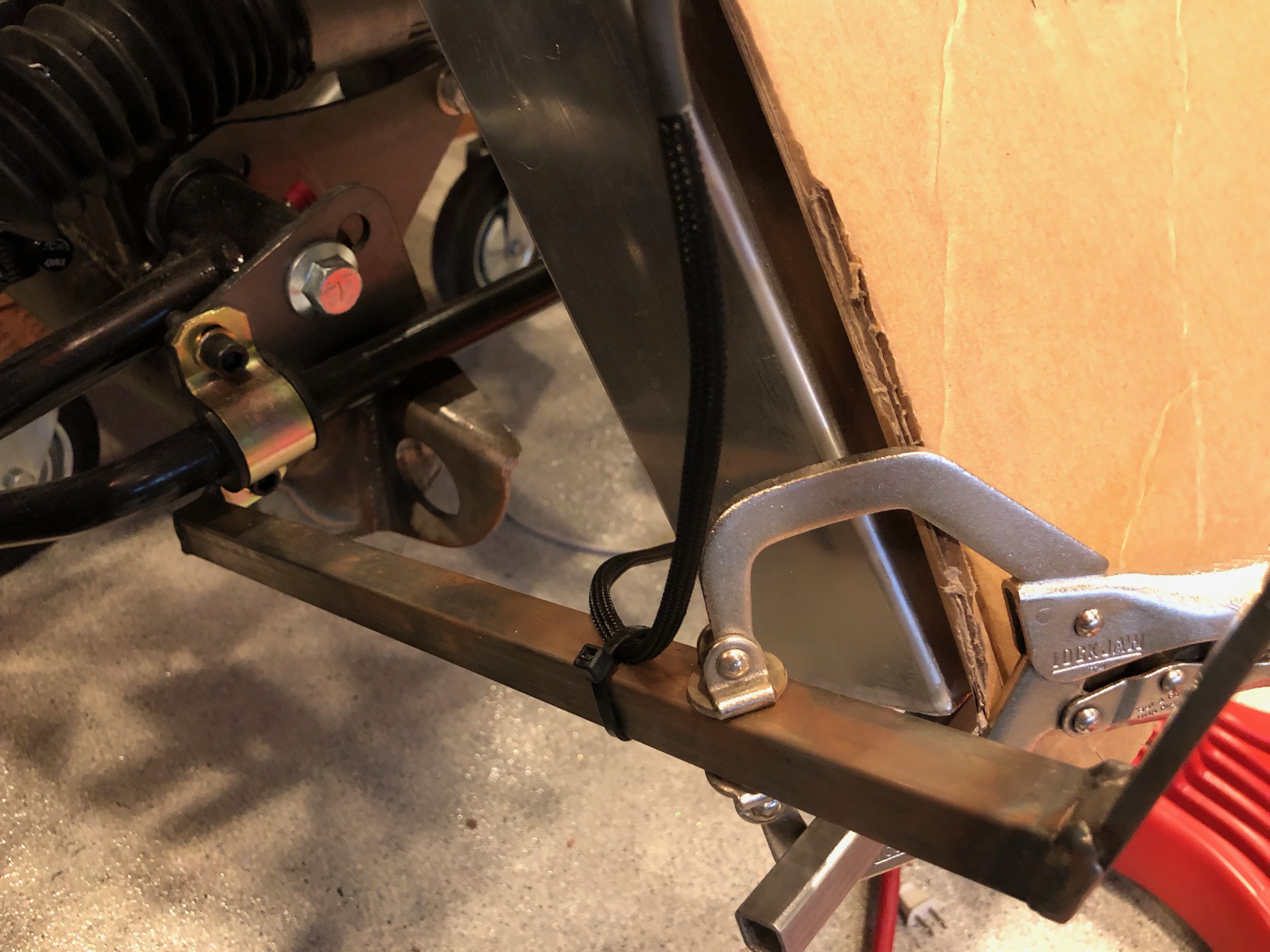
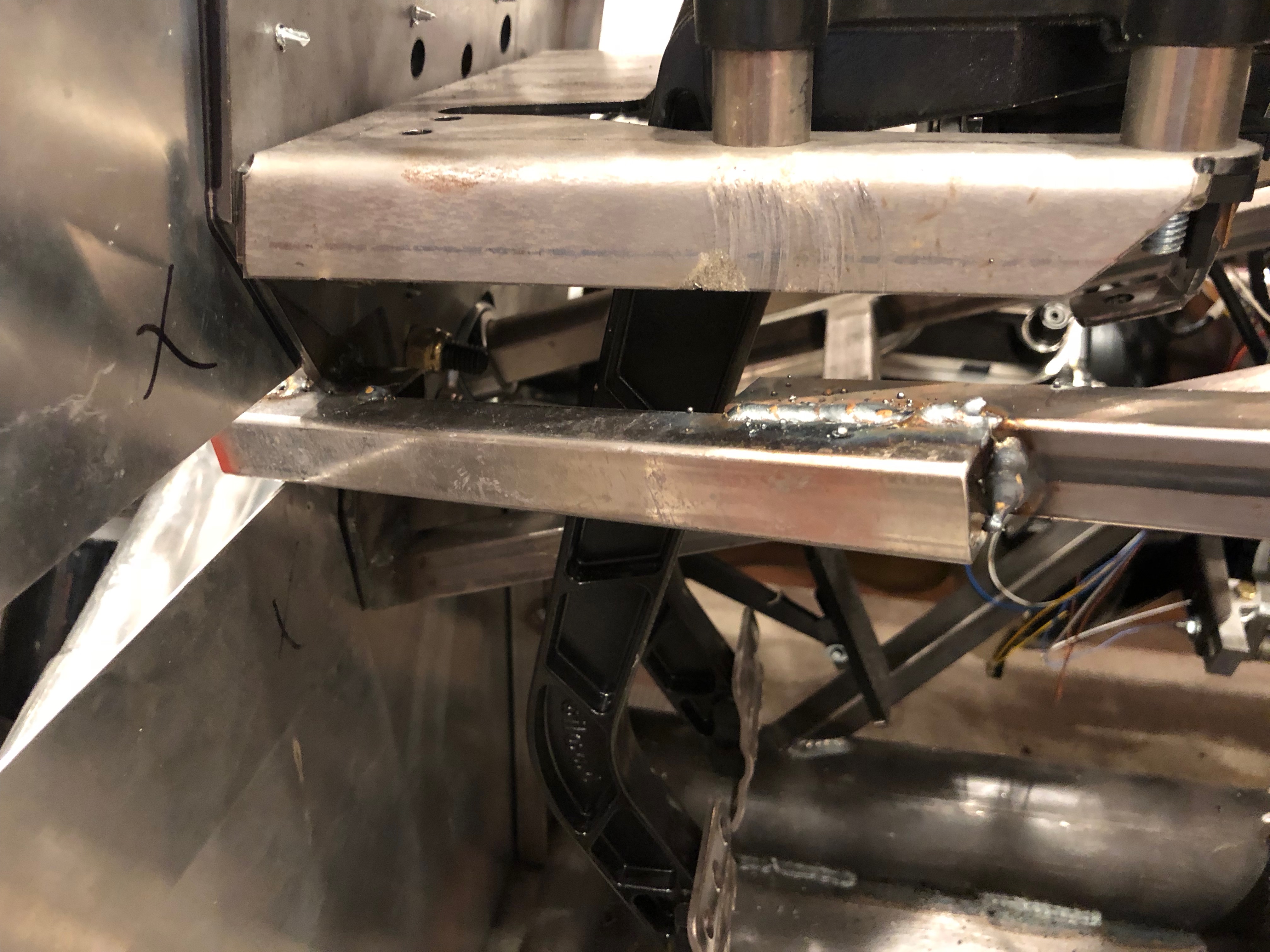
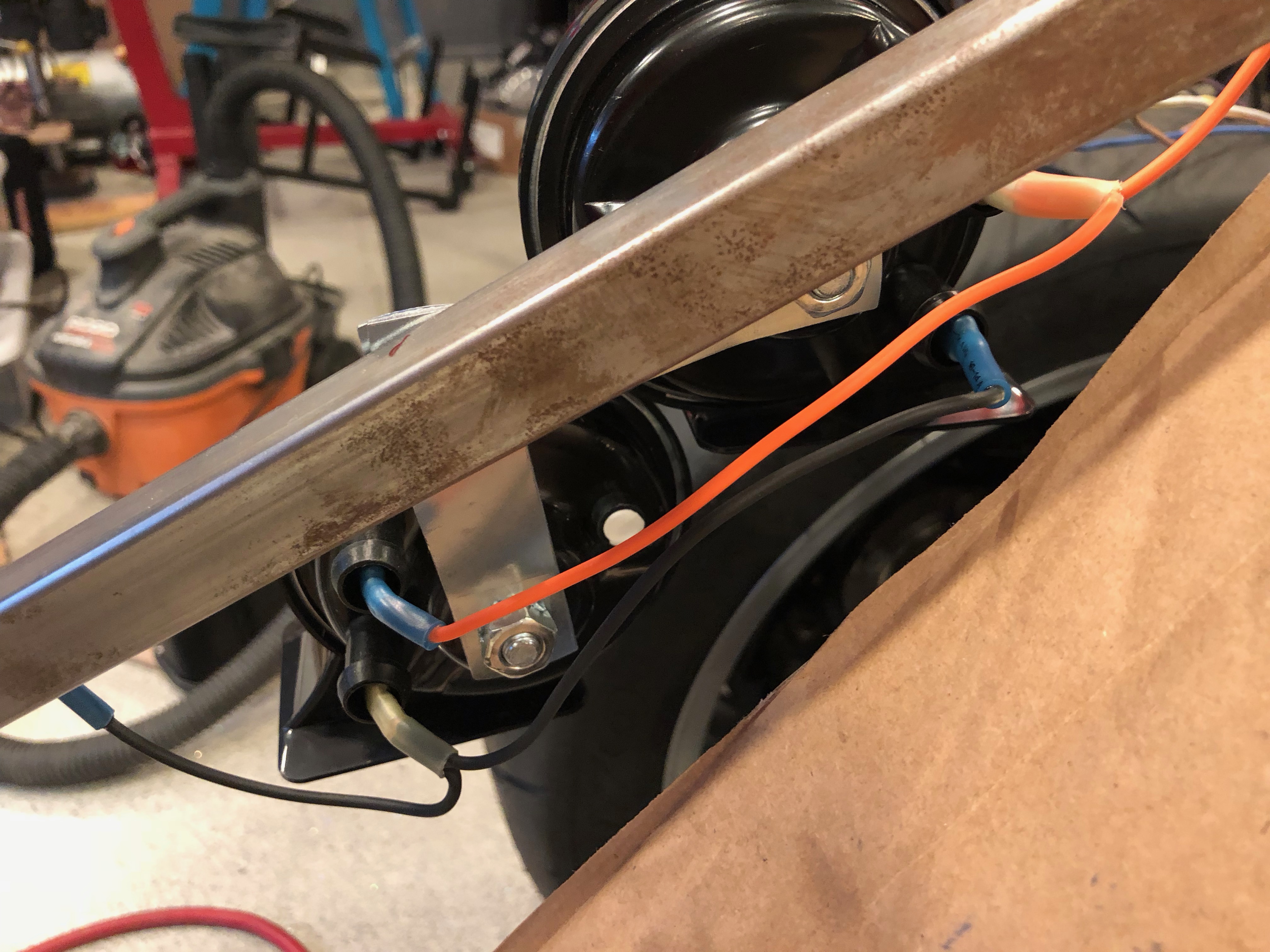
Another pair of wires drop down to the lower chassis tubing for the fan wiring. There will be a rivnut and zip-tie mounting block installed here, but it’s just zip-tied for now.

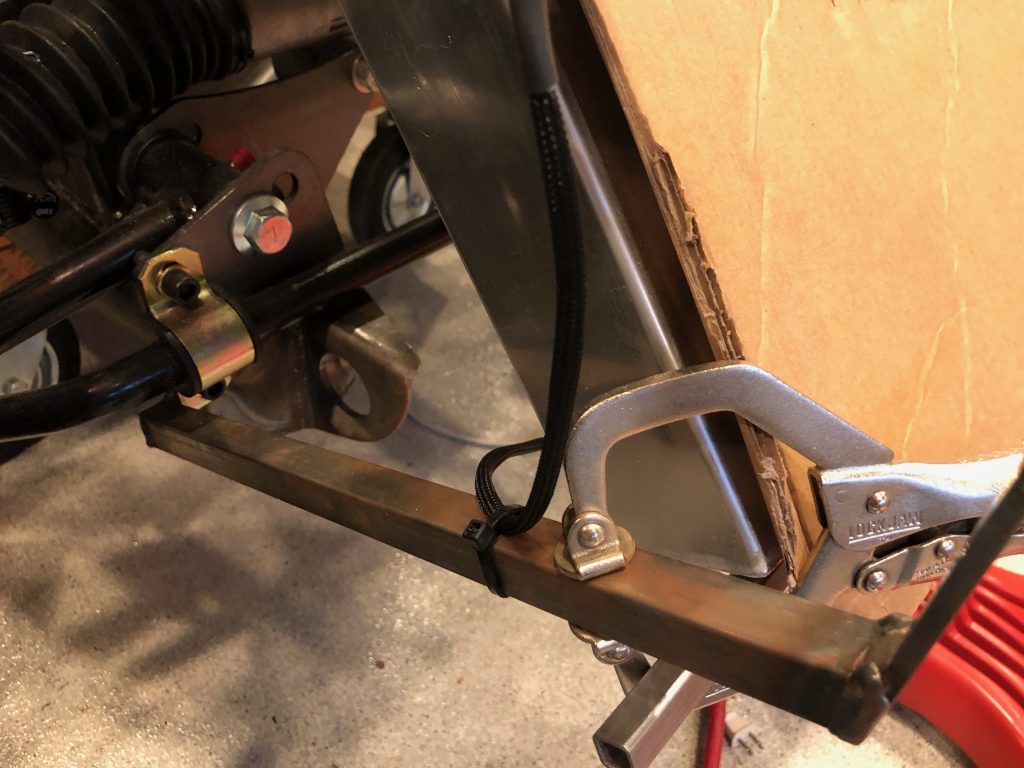
From there, it runs across to the fan. There will be a couple more attachment points across the lower edge of the fan shroud to secure this cable.

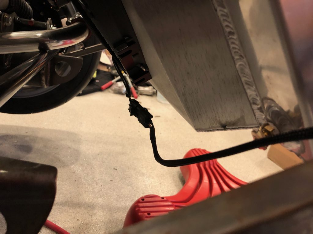
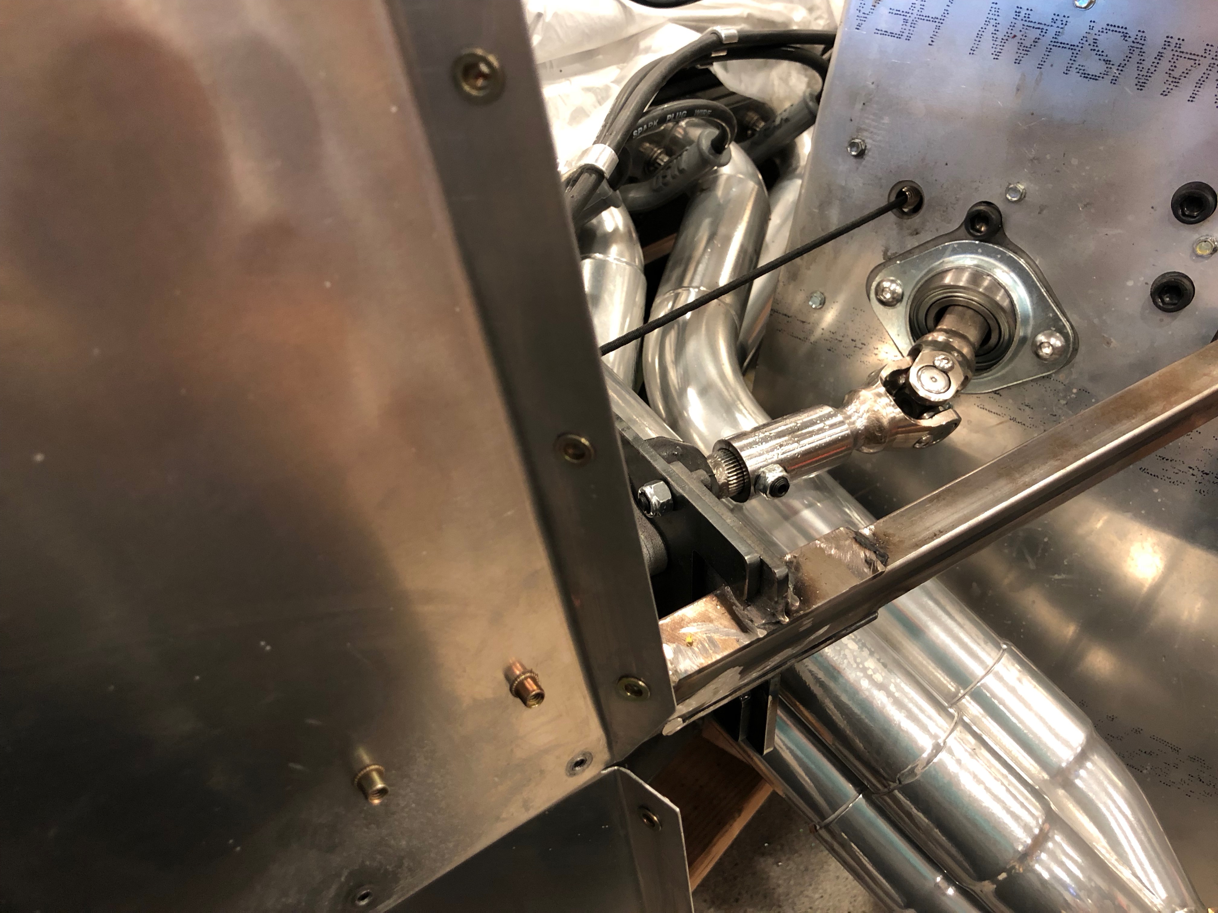
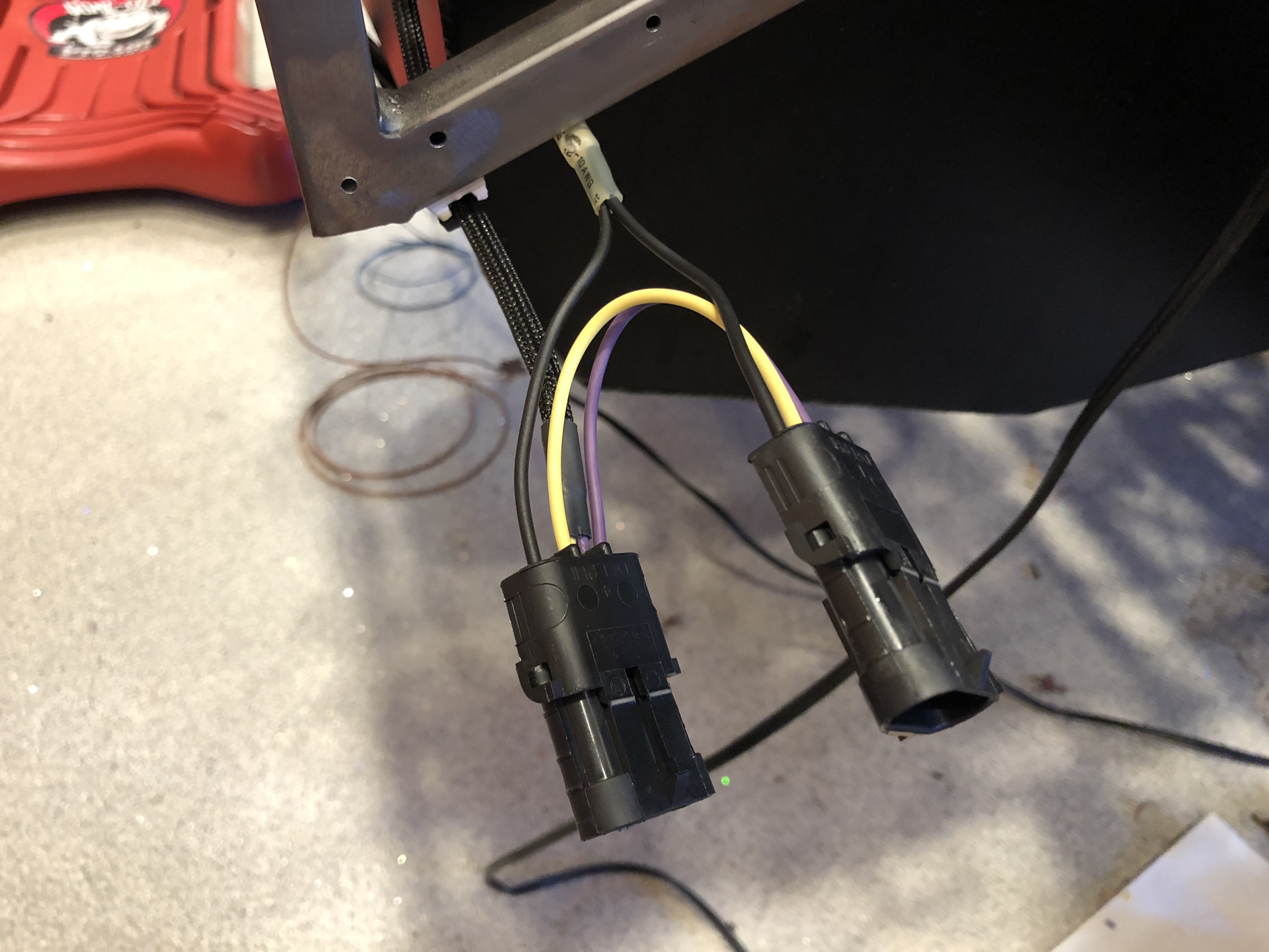
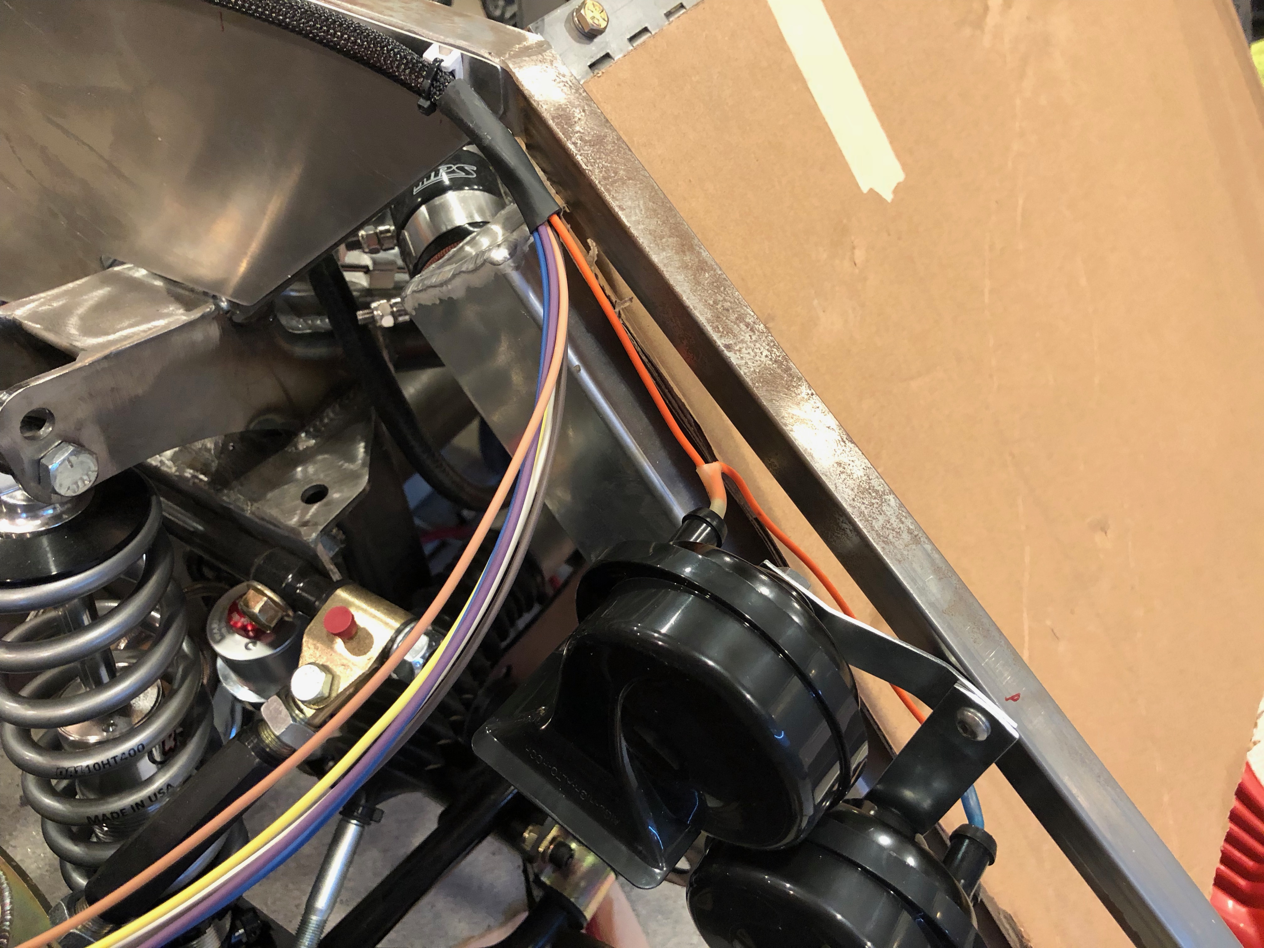
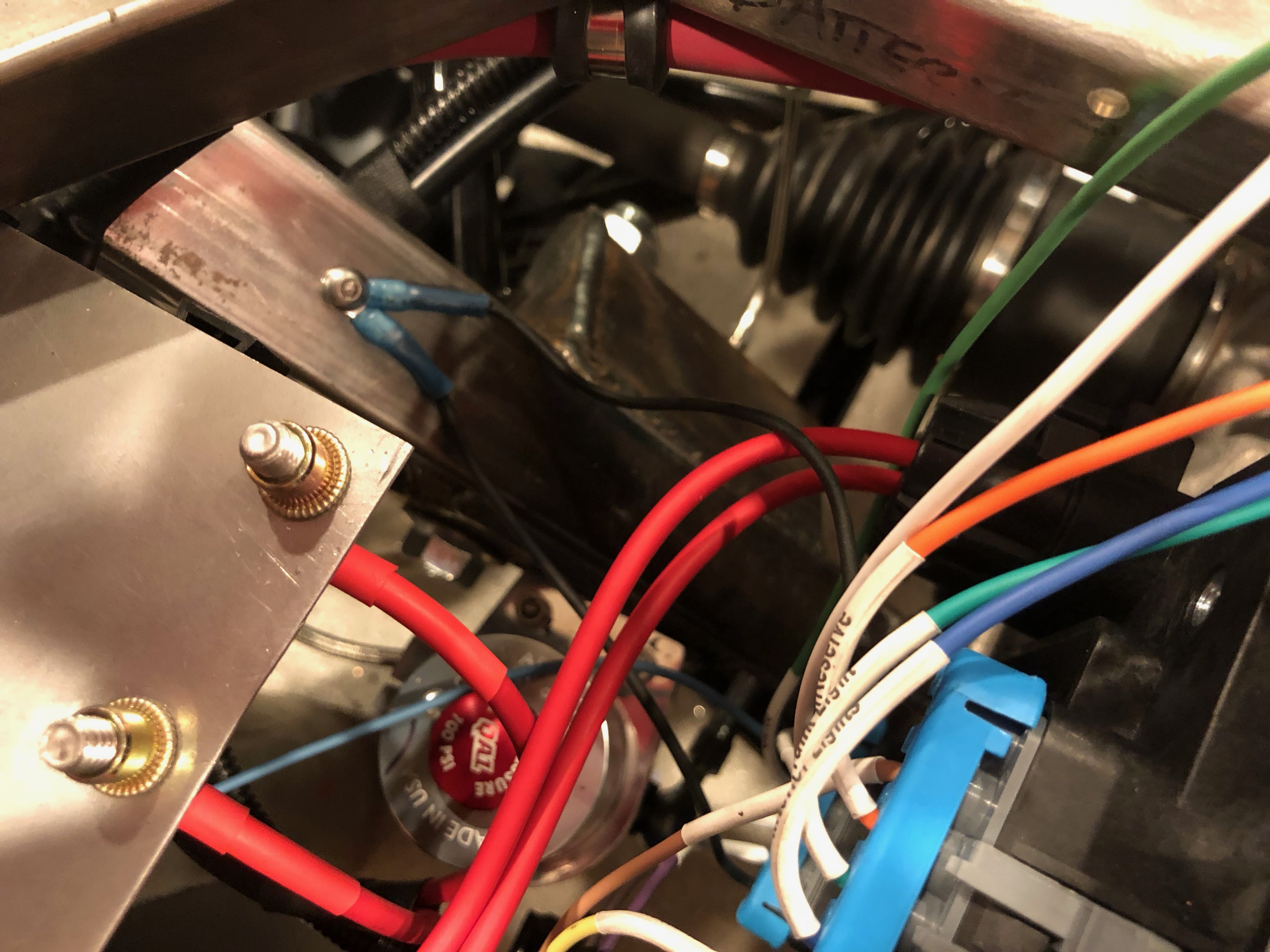
The cable that cuts across the top of the radiator runs down the left chassis member and terminates in a similar set of six wires. The two ground wires are secured to the chassis with a screw behind the bundle of four terminals to the left.

Adding Rivnuts for Panel Attachment

Since we’re going to completely disassemble the car before final assembly so that we can finish the chassis, we’ve been temporarily attaching all of the aluminum panels with sheet metal screws. We had been planning on riveting the panels on during final assembly, but if we ever need to remove the panels, we’d have to drill out the rivets. I don’t know how likely that is, but I’m really trying to plan for any possible future maintenance. To that end, we decided to attach all panels with screws.

I started drilling out the attachment holes and installing rivnuts. I haven’t counted how many of these I’ll need, but I’ve used up the first 100 I ordered and I’m a long way from being done. I’m guessing there are close to 500 over the whole car.

Added Rivnuts to F-Panels

The f-panels have flanges on the rear edge that will attach to the panels that close off the rear of the front wheel wells. Most people rivet these panels on, but apparently they interfere with getting the body on and off, so some people recommend making them removable. I drilled a series of holes and added rivnuts to them so that I will be able to attach the panels with screws.

I also added a couple of rivnuts to the inside of the left f-panel to attach the control box for the electric power steering. You can also see a rivnut in the chassis that will be the grounding point for the electric power steering system.

Welded New Chassis Tube

I clamped a piece of 3/4″ tubing to the outside of the forward tube and welded it in place. It was then fairly easy to flex the two pieces of tubing into alignment and weld the rear pieces together. I’ll finish going all the way around the weld and clean it up with a grinder when the car comes back apart.

Taillight Wiring and Clutch Pedal Clearance

I installed Weather Pack connectors on several of the tail lights. I ran out of three-conductor connectors though, so I couldn’t finish all of them.

I also installed the female connectors on the chassis on both sides. These are electrically identical and all lights have identical connectors. This is possible because the InfinityBox lets you use the same lights for brakes and turn signals. Although this is possible with a combination of relays in a traditional wiring harness, most builders don’t wire it this way. They end up using the dim filaments in all four tail lights for their parking lights, but the bright filaments in one pair of lights for the brakes and in the other pair of lights for the turn signals. In our car, all four bright filaments will be used for brakes and turn signals.

When I moved the pedal box up, it caused interference with the 3/4″ tubing that cuts through the middle part of the driver footbox. There must have been some stress in this tubing because the two pieces shifted out of alignment with each other when cut apart. I’ll weld in a new piece of 3/4″ tubing on the outside of this tubing. I’ll try and realign the pieces of tubing when welding.

It took a few extra trims on the forward end of the tubing to allow the pedal to go all the way to the front of the footbox, but I now have full clutch travel.

Horn and Taillight Wiring

I cut back the sleeving on the wiring harness to the front right of the car and put a terminating piece of heat shrink on it to keep it from unraveling. I then cut the horn wire and created a jumper between the horns.

I also installed a grounding point on the forward 3/4″ tubing and grounded the horn there. The lights and fan will also ground here.

The ground wire also jumpers between the two horns.

I also added a grounding point on the left side diagonal chassis member to ground the rear load cell.

I figured out which wires will be routed to the rear lights and put some expandable sleeving over them. I’m routing them over the top of the fuel tank.

I used a solder sleeve to tee the parking light wire and then dropped the wires down behind the tank near the center.

Wiring Harness and Horns

I slipped some expandable sleeving over the bundle of wires going to the front of the car and secured the harness to the firewall to the left of the load cell.

The harness routes under the upper chassis tube and is secured to the outside.

The harness will split at the top of the radiator and route to the various loads at the front of the car: lights, fan, and horn. I went ahead and installed the horns along the upper tubing beside the radiator.

Spliced Into Front Load Wires

I used some solder sleeves to splice the fusible links into the six wires on the front load cell that need to be indicated on the dash.

I put an extra piece of heat shrink over the solder sleeve to protect them.

I also added a rivnut to the side chassis tubing to  ground the front load cell.