Pedals and Strut Spacers

I finished adjusting the brake balance bar and adjusted the brake pedal to stop just before hitting the 3/4″ square tube at the top of the picture. Afterward, I adjusted the clutch pedal resting position to be aligned with the brake pedal. I ended up having to cut off about 1/4″ of the threaded shafts on all three master cylinders in order to position the pedals correctly.

After finishing the brake and clutch pedals, I installed the accelerator pedal to the bracket at the front of the foot box. I adjusted the brake and clutch pedal pads to get maximum width and roughly center the brake pedal.

Finally, I installed all of the spacers that I machined last night. Everything fit perfectly, but most of them were pretty tight. Once the spacers and chassis are powder coated, I’m not going to be able to get them in without trimming them a little bit, but that can wait until everything comes apart.

Turned Spacers for Struts and Alternator

I needed to make custom length spacers for the struts and alternator mount, so I stopped by the TechShop after dinner to turn them on the lathe. I ordered a 2″ spacer from March Performance that is already powdercoated, so I wrapped it with some tape to protect the finish. I turned this down to 1.745″

I need spacers of a bunch of different lengths for the struts. I picked up some 0.509″ ID tubing with 0.058″ wall thickness from McMaster Carr and rough cut them on the chop saw about 0.100″ long. I then turned down each end to make them perfectly square and the right length.

Trimming the spacers leaves a burr on the inner edge, so I repositioned the cutter and trimmed it off of each end of all of the spacers.

Here are the finished spacers. I’ll powdercoat these when the car comes completely apart for chassis finishing, but for now I’m going to install these bare.

Afer I got home, I installed the alternator spacer.

I installed it along with the oil dipstick tube. The bottom of the tube is installed with a little bit of black RTV to prevent oil leaks.

Installed Pedal Box

Jenn’s been sick since we got back from vacation. She’s disappointed to not be able to work on the car, but she wants to see some progress, so she’s been fine with me working on the car alone the last few days.

Next up is to install the pedal box. The complete kit comes with the Wilwood pedal box that contains the brake and clutch pedals. The brake pedal is set up to depress two master cylinders (one for the front brakes and one for the rear). The clutch pedal can use a master cylinder for those (like us) who are using a hydraulic clutch, or it can be configured to use a clutch cable for those running a manual clutch.

Both the clutch and brake pedals have switches installed so that systems can know when they’re depressed. The switches are mounted to tabs that need to be installed on the pedal box. To drill the holes, I clamped the tabs to the opposite side of the mounting flange since there is no room to drill from the other side. If you do this, don’t push the tab all the way down against the adjacent side flanges since they slope up toward the pedal and the hole won’t be aligned when you move the tab to the other side of the mounting flange. I just eyeballed it and it worked out great. You can see the right tab is already mounted and the left is ready to be drilled.

Once the tabs are in place, the switches can be installed. I’ll adjust the offset for these once all the systems are hooked up.

When I tried to install the pedal box in the car, two of the screws that I installed yesterday interfered. I removed them, installed the pedal box and then drilled through this flange. After removing the pedal box, I enlarged these holes to provide clearance for the screws (and eventually the rivet shop heads).

After fitting the rear mounting plate, I marked and drilled holes through the lower 3/4″ square tubing. Initially, they landed almost flush with the edge of the tubing. I couldn’t drill the holes there since that would compromise the side of the tubing. I ended up shifting the holes over about 1/16″. There is enough flex in all of the components that they can absorb some offset. You just need to make sure all of the bolts are installed loosely before tightening everything down.

You can see that the clutch reservoir (closest in the picture) has a larger bore than the brake cylinders. After installing everything, I realized that the brake balance bar was misadjusted from the factory. I ended up removing one of the brake cylinders so that I could adjust the side-to-side clearance of the balance bar. After adjusting the balance bar, I threaded in the master cylinder shafts until the cylinders open all the way up when the pedals are released.

Parking Brake and Aluminum Panels

We’re relocating the parking brake to the top of the tunnel, so I wanted to assemble the mechanism so we could begin determining the best location. We can’t make a final determination until the transmission and seats are in place though.

Since we deleted the brakes from the kit order, we didn’t get the parking brake cables. Since we’re moving the parking brake anyway, the stock kit from FFR probably wouldn’t work without modification. Fortunately, Wilwood sells a universal kit (330-9371) that can be trimmed to exactly fit each application.

I fit and drilled the firewall to the chassis. I ran out of sheet metal screws and need to pick up some more.

I also drilled the foot box front panel to the chassis. I ended up laying out a couple of holes under the 3/4″ square tubing and needed to use a right angle drill to drill them.

New Rear Shocks and Sway Bars

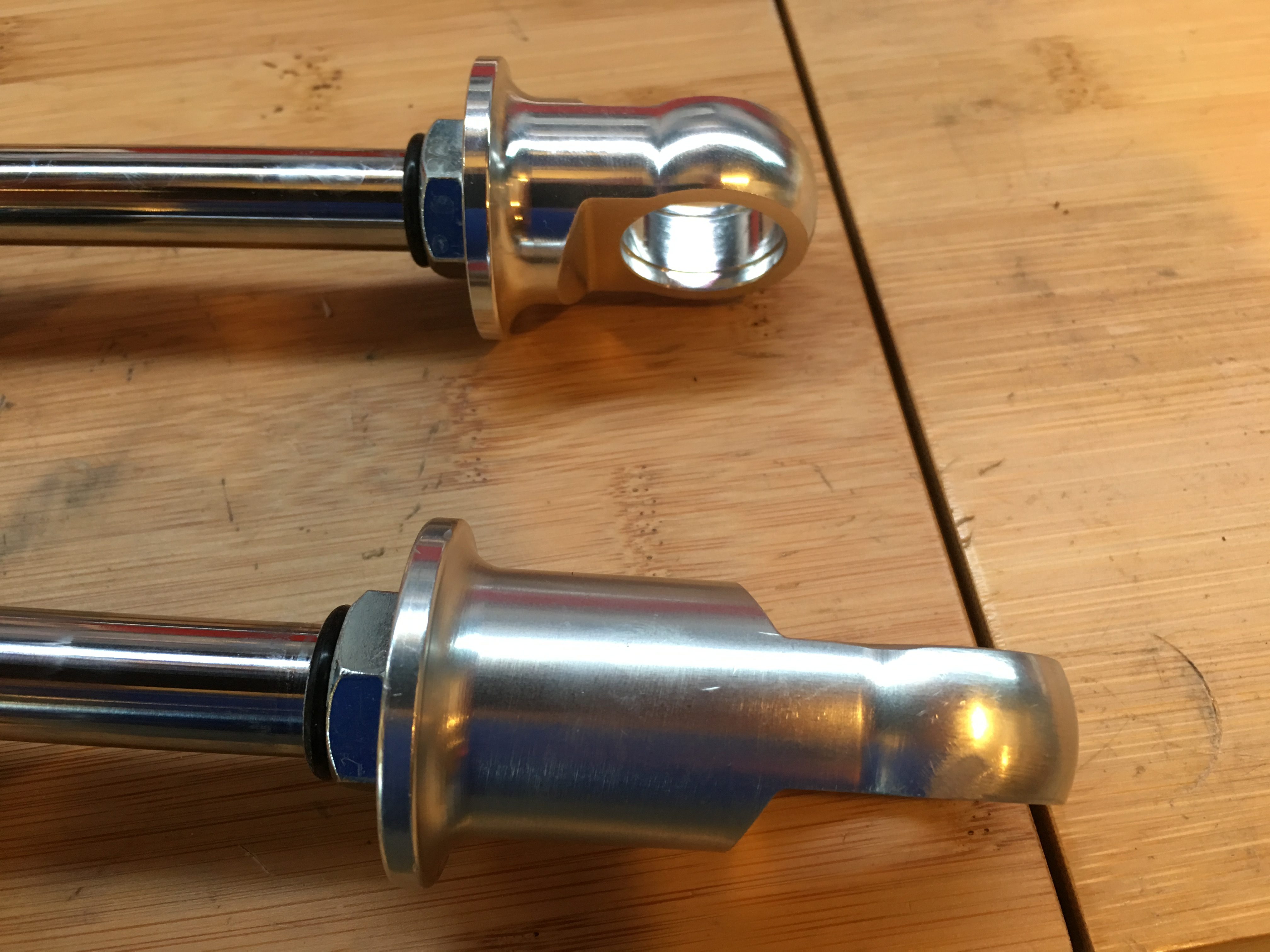
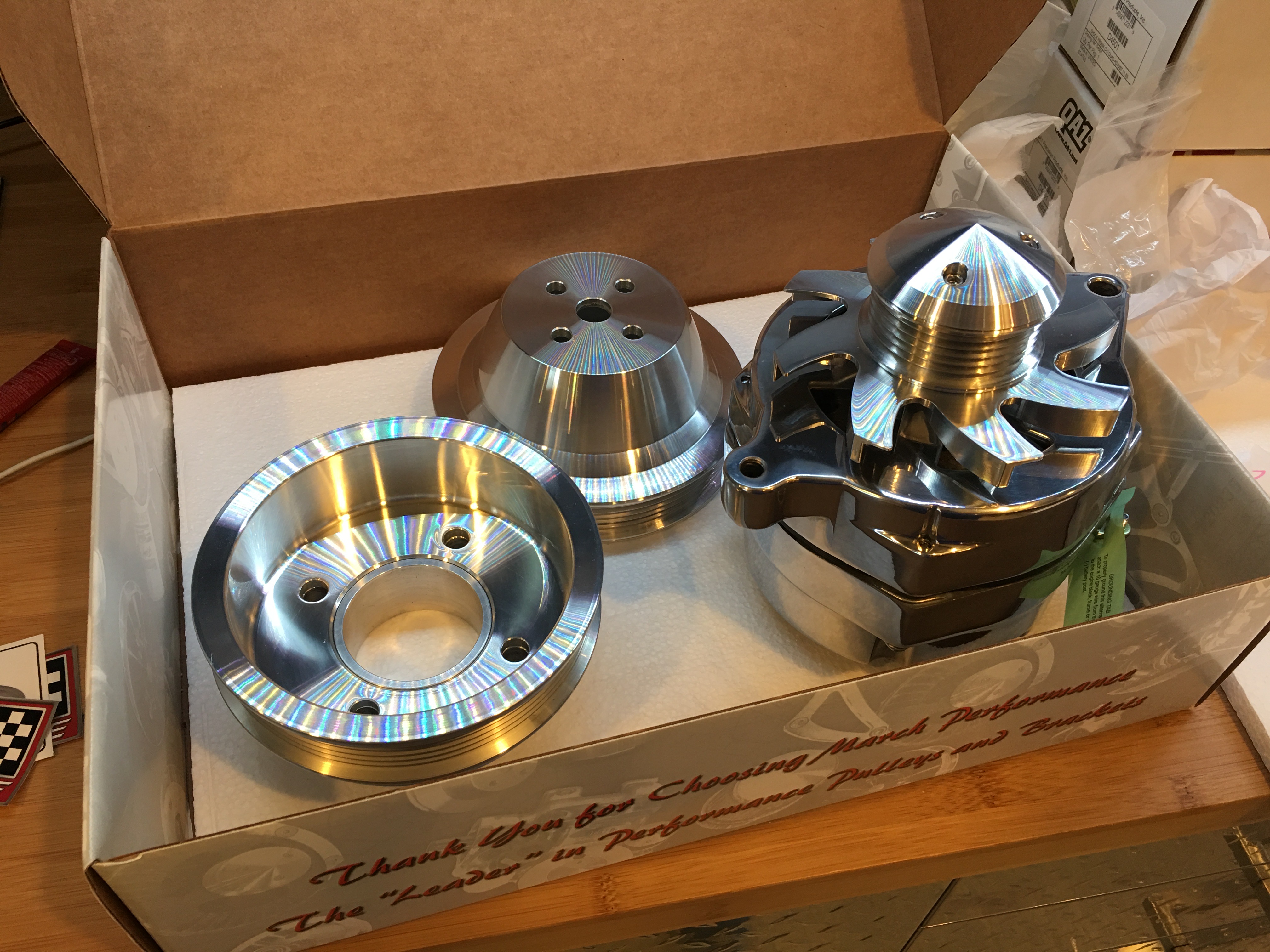
We got back from AirVenture yesterday and our new shocks had arrived along with the extended eyelets. The eyelets just unscrew from the shock shafts and the new ones thread on.

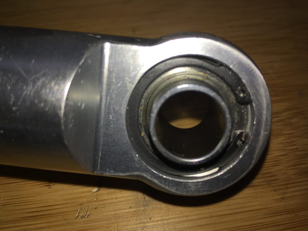
I really like how the QA1 shocks have easily serviceable components. The bearings in the eyelets are held in with snap rings, so they can easily be moved from the old eyelets to the new ones. If they ever need to be replaced in the future, it can be done without replacing the entire shock.

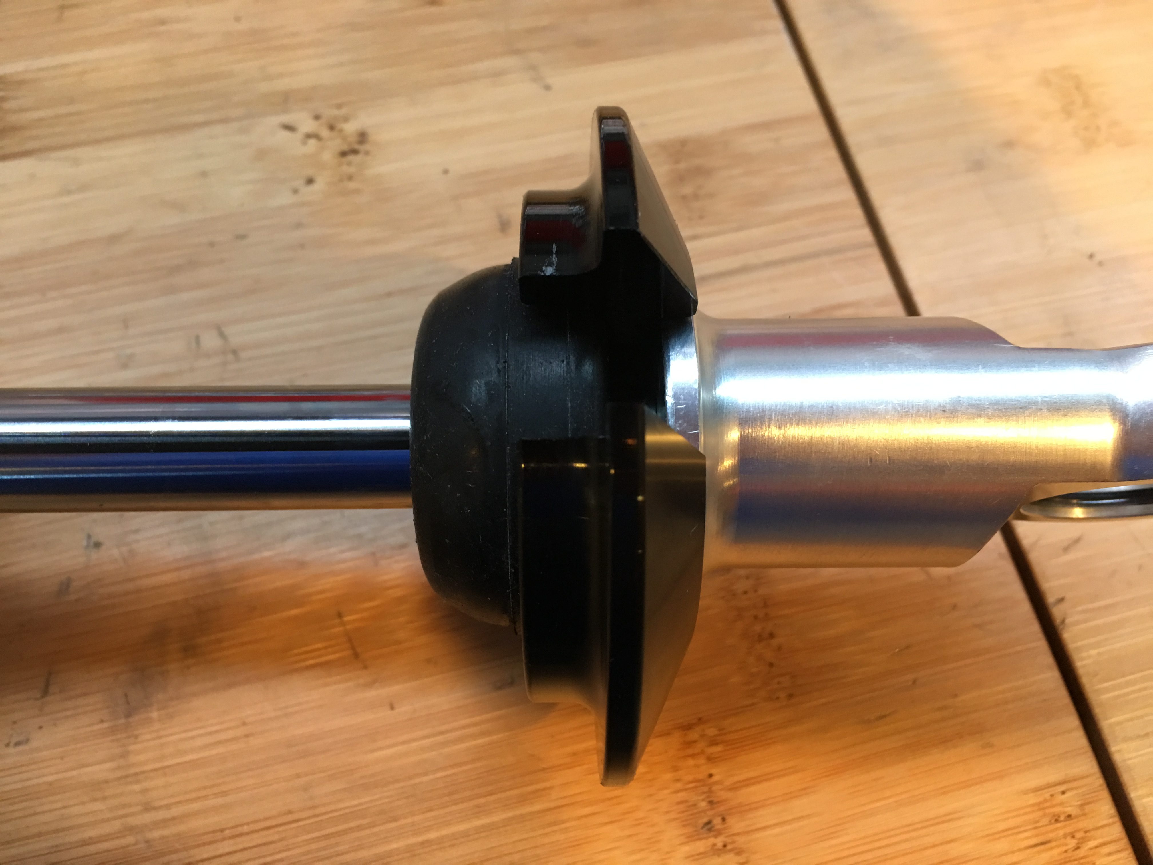
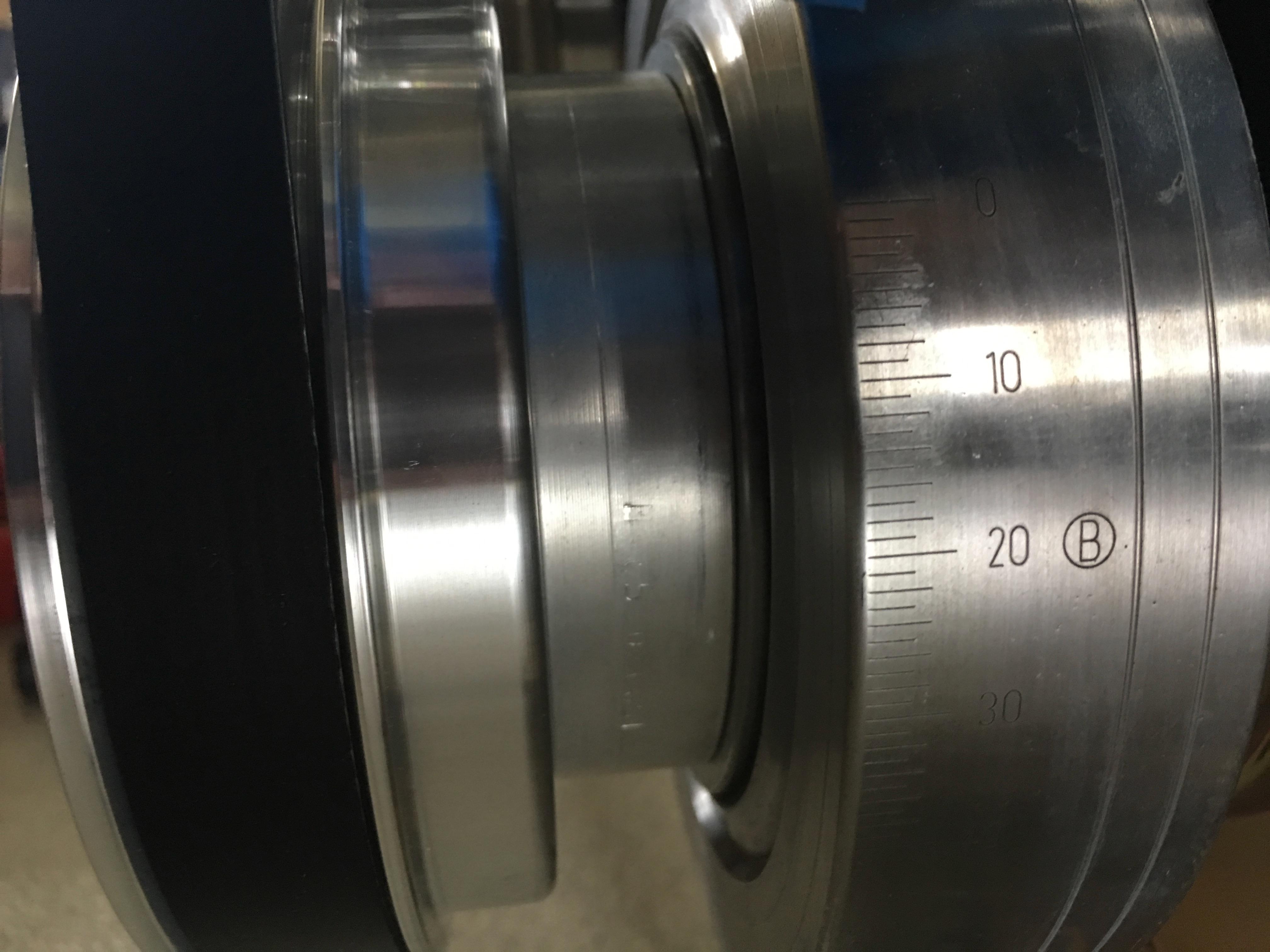
Since I had the eyelets off, I installed the bump stops onto the shafts.

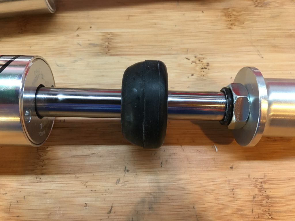
I couldn’t find any instructions that indicate which direction these should face, but they seemed to fit in the upper spring seat better in this orientation.

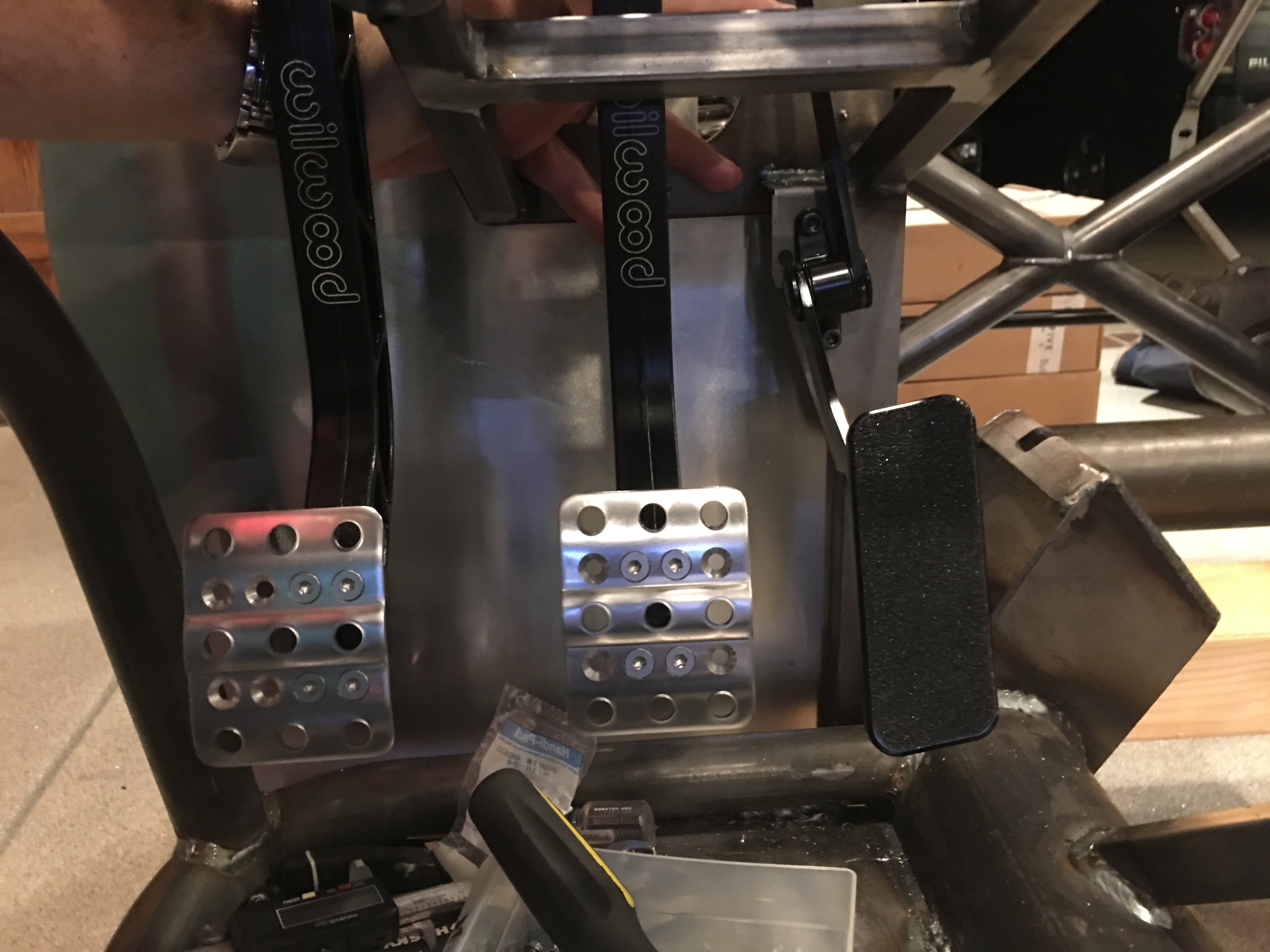
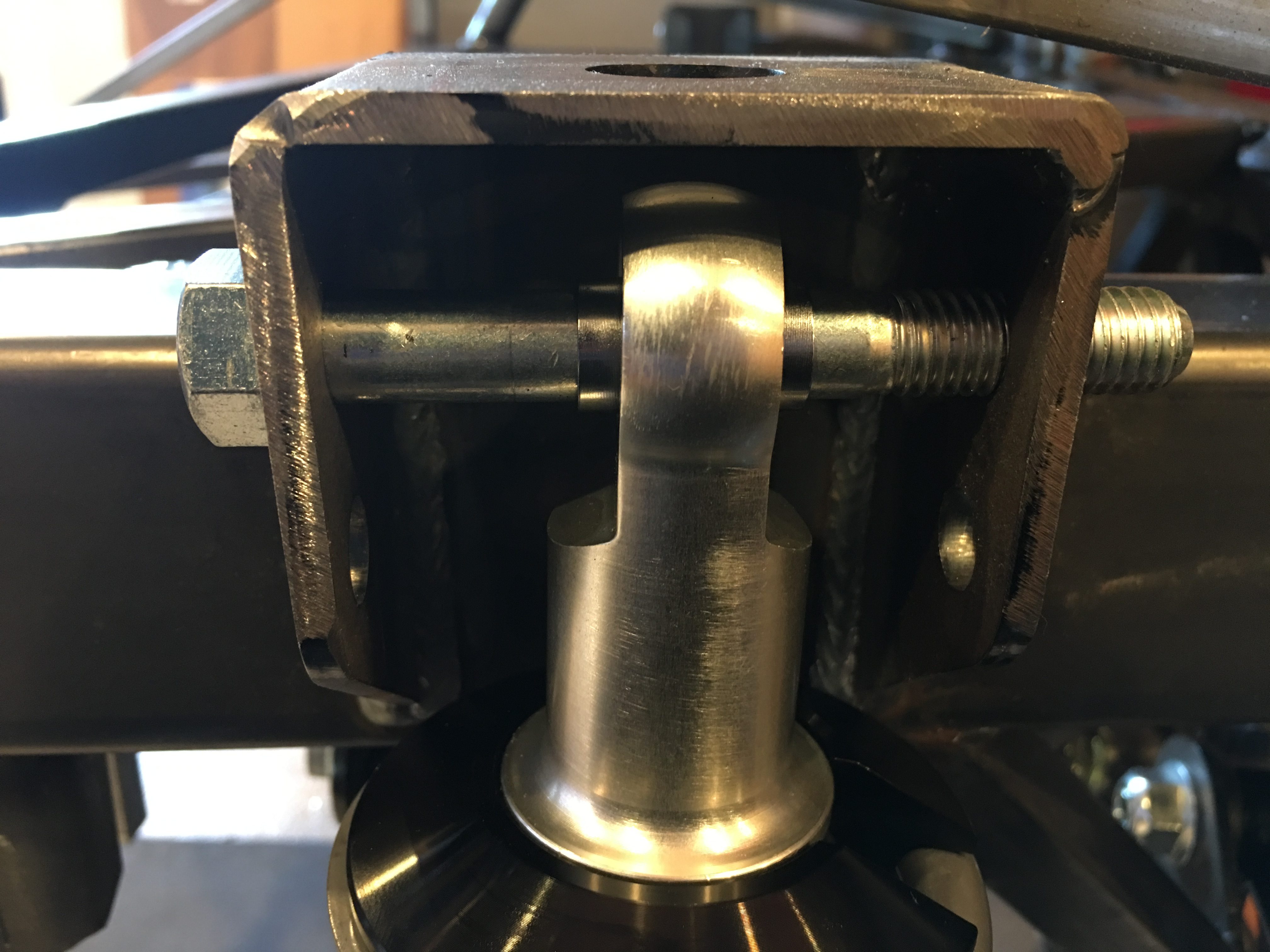
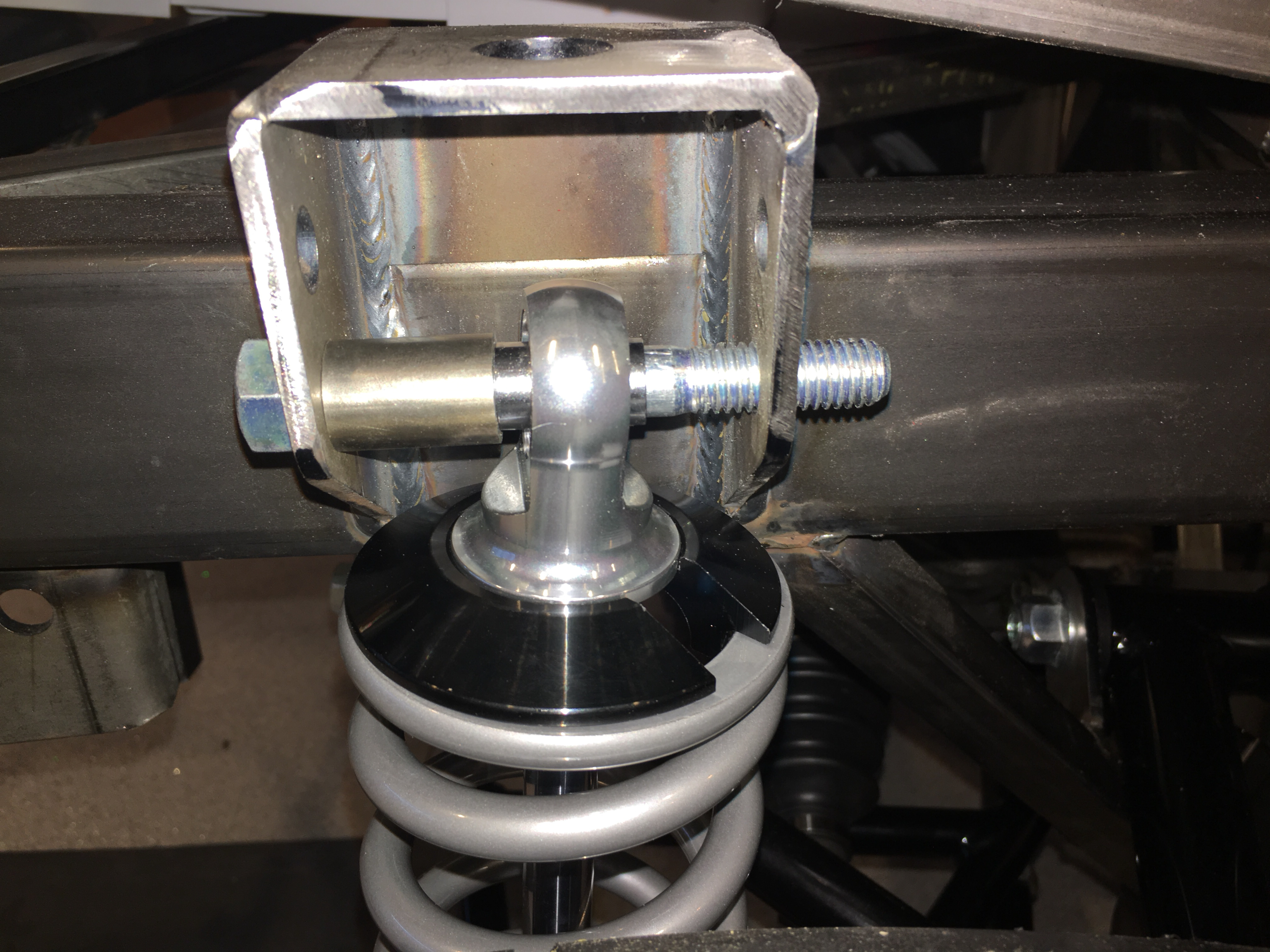
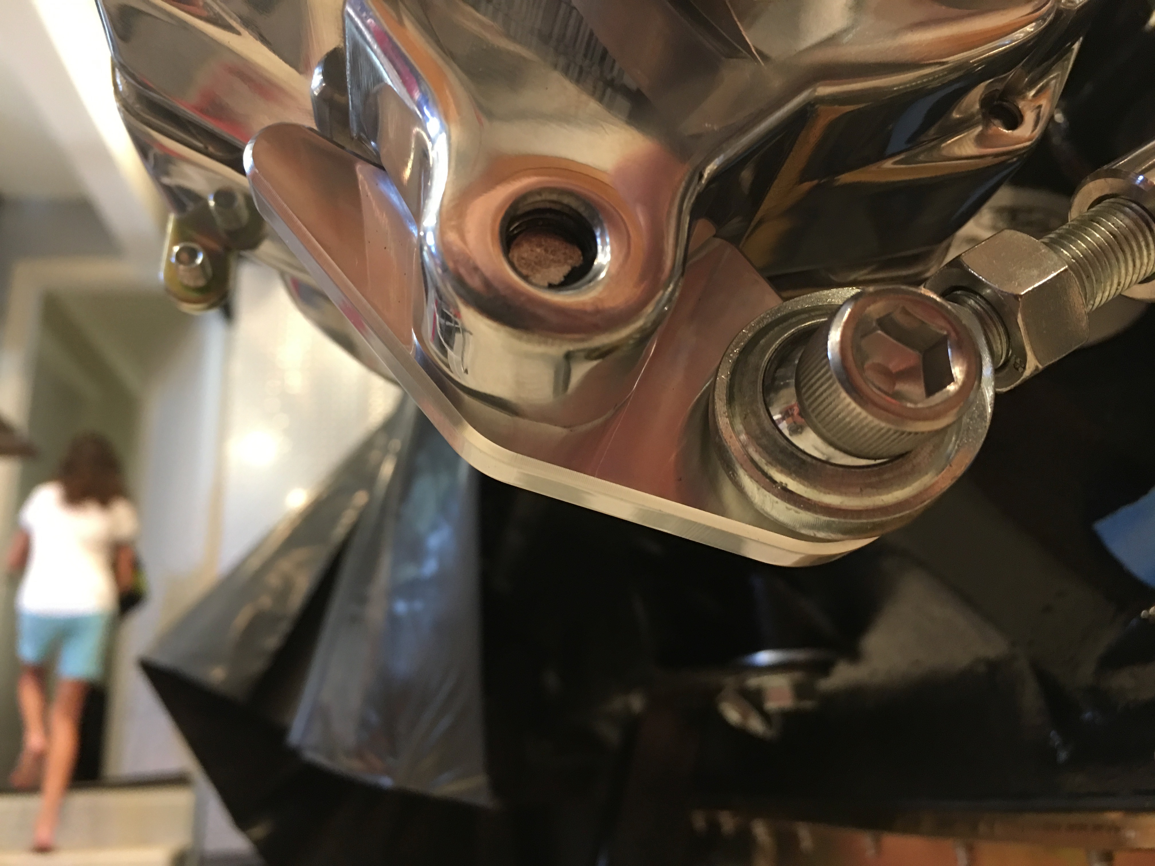
With the extended eyelets installed, I could mount these in the upper mounting hole.

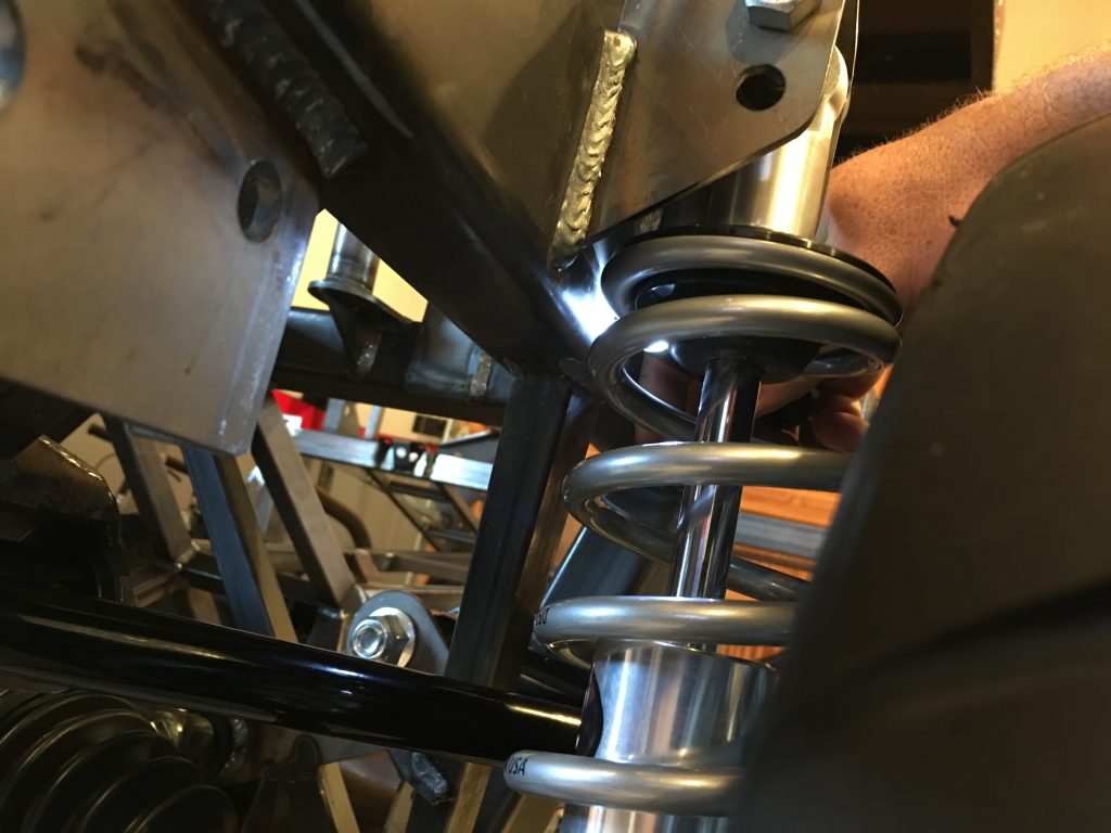
I still need to mount the upper end of the shock slightly off center to have the spring seat be centered in the bracket.

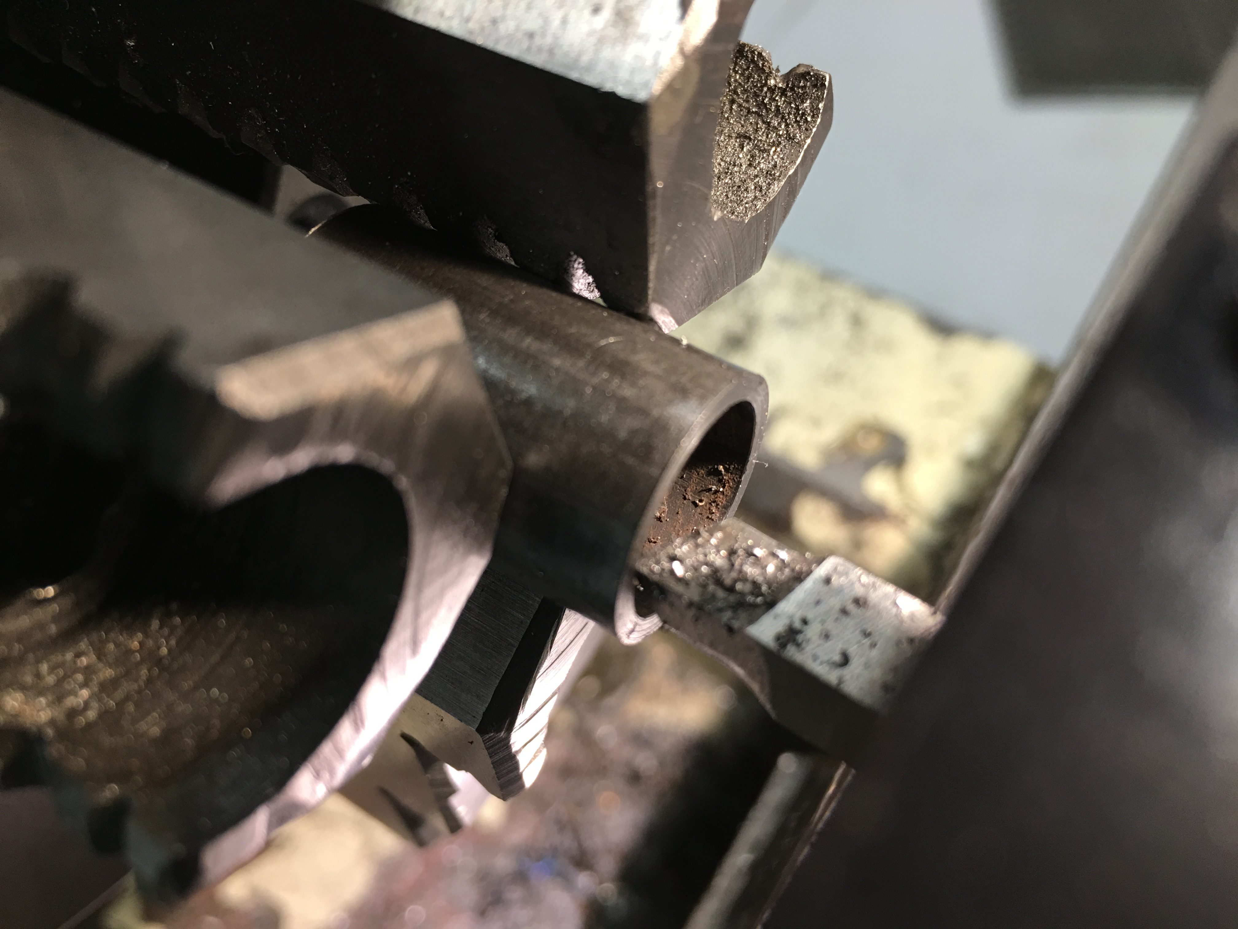
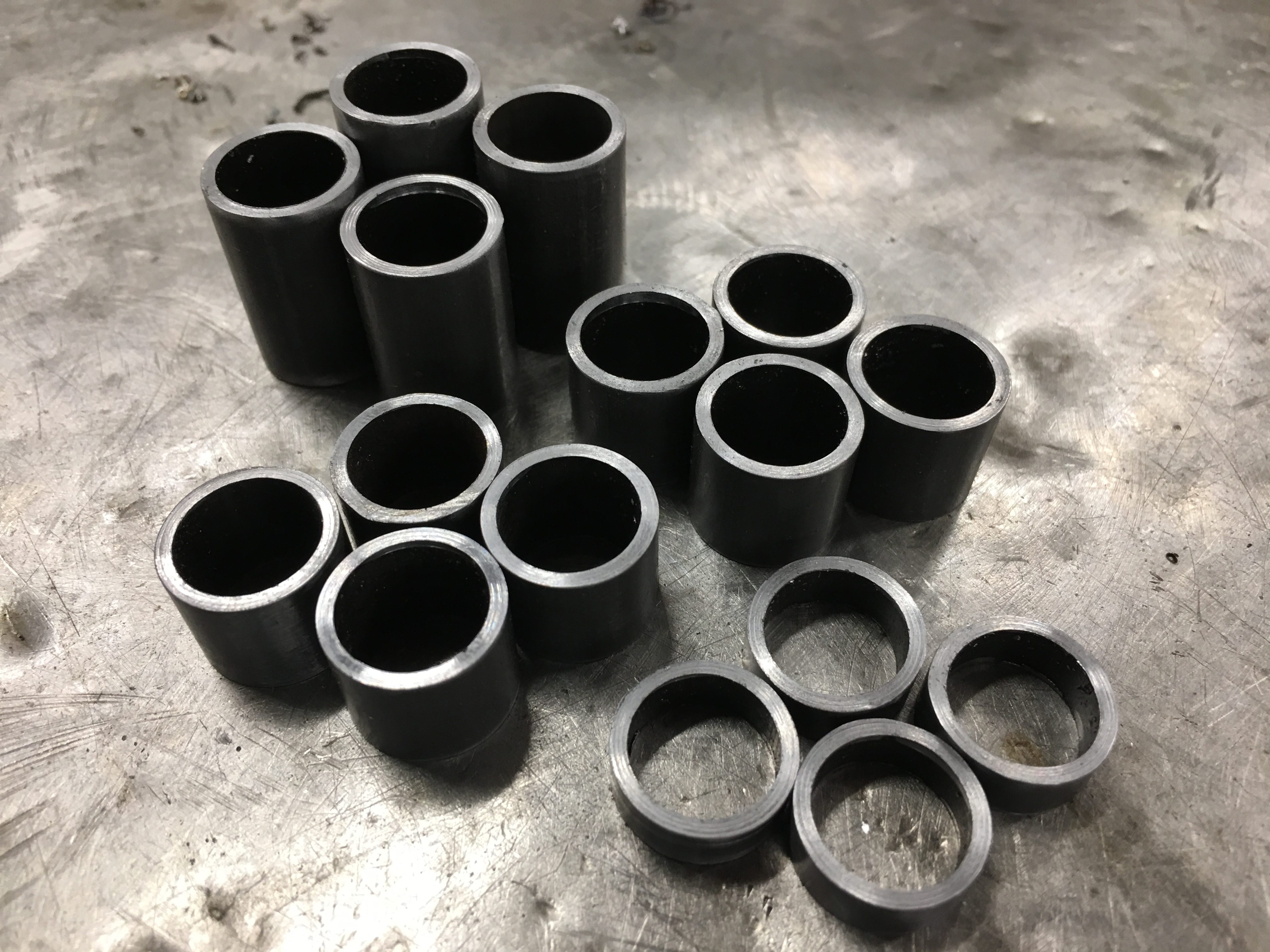
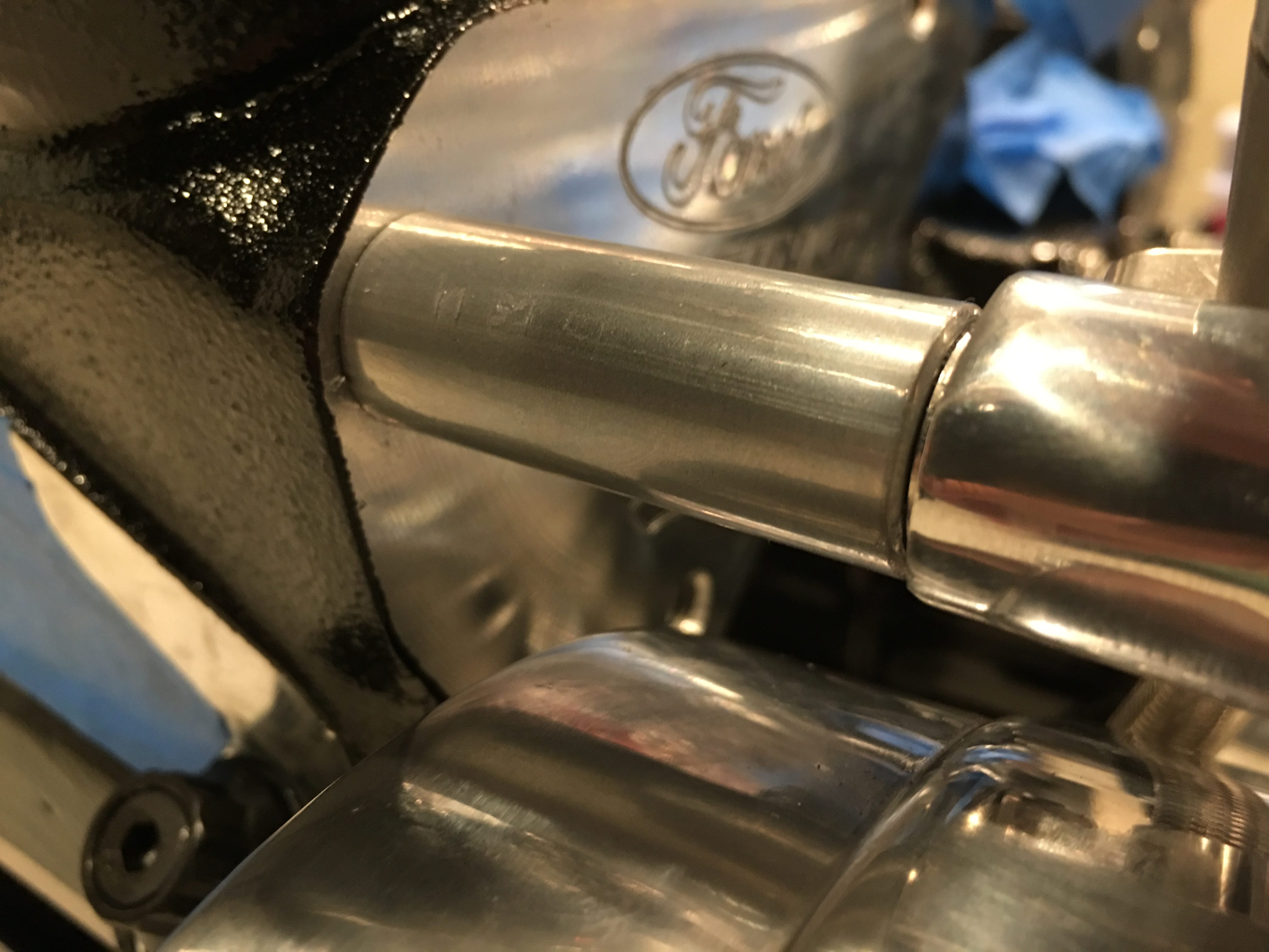
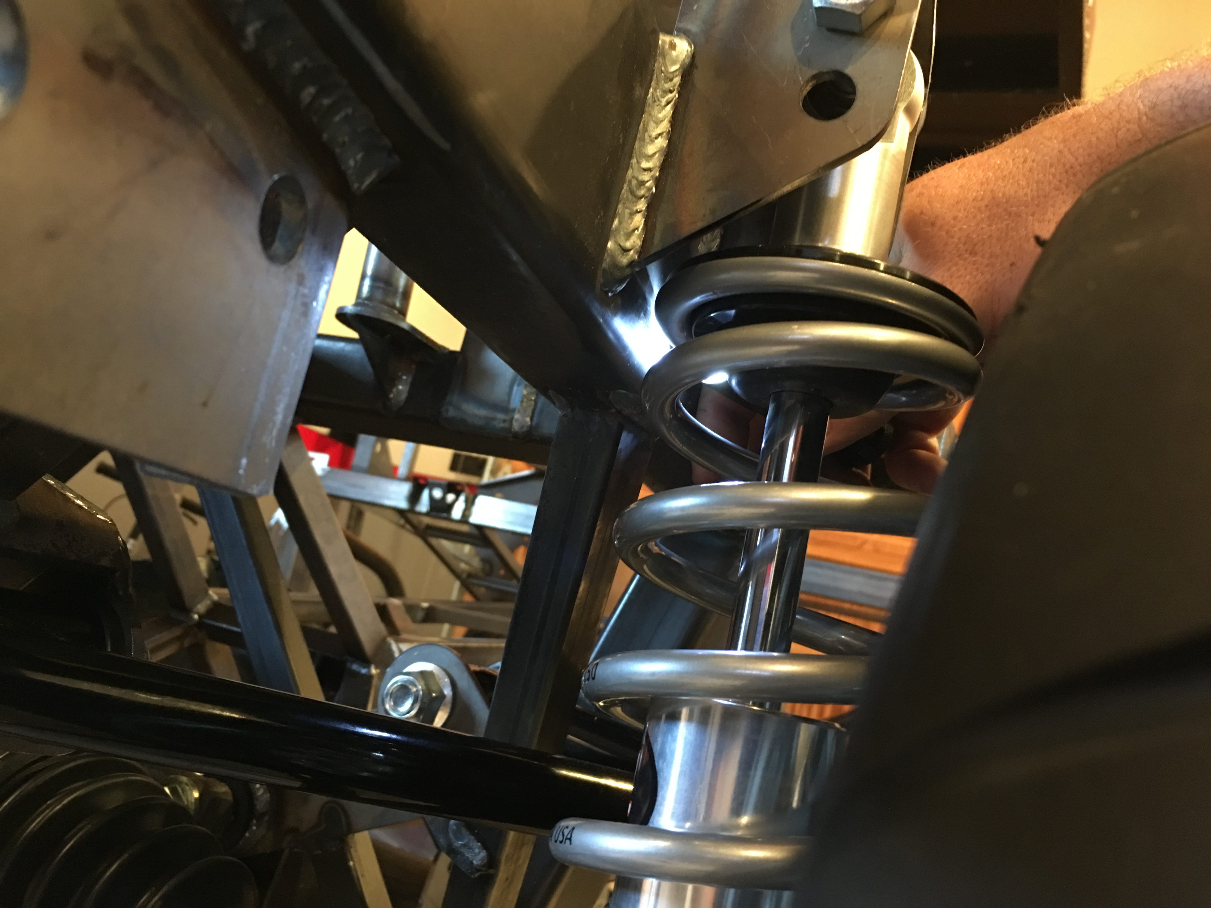
The upper mounting hole pushes the shock slightly outboard, so the spring now clears the rectangular tubing. Other than fine tuning the spring rates, I think these shocks will work great now. With everything test fit, I measured for all of the spacers. Unfortunately, the spacers they shipped in the kit aren’t sufficient for fabricating all of the ones I need. I ordered some tubing from McMaster-Carr and will fabricate those soon.

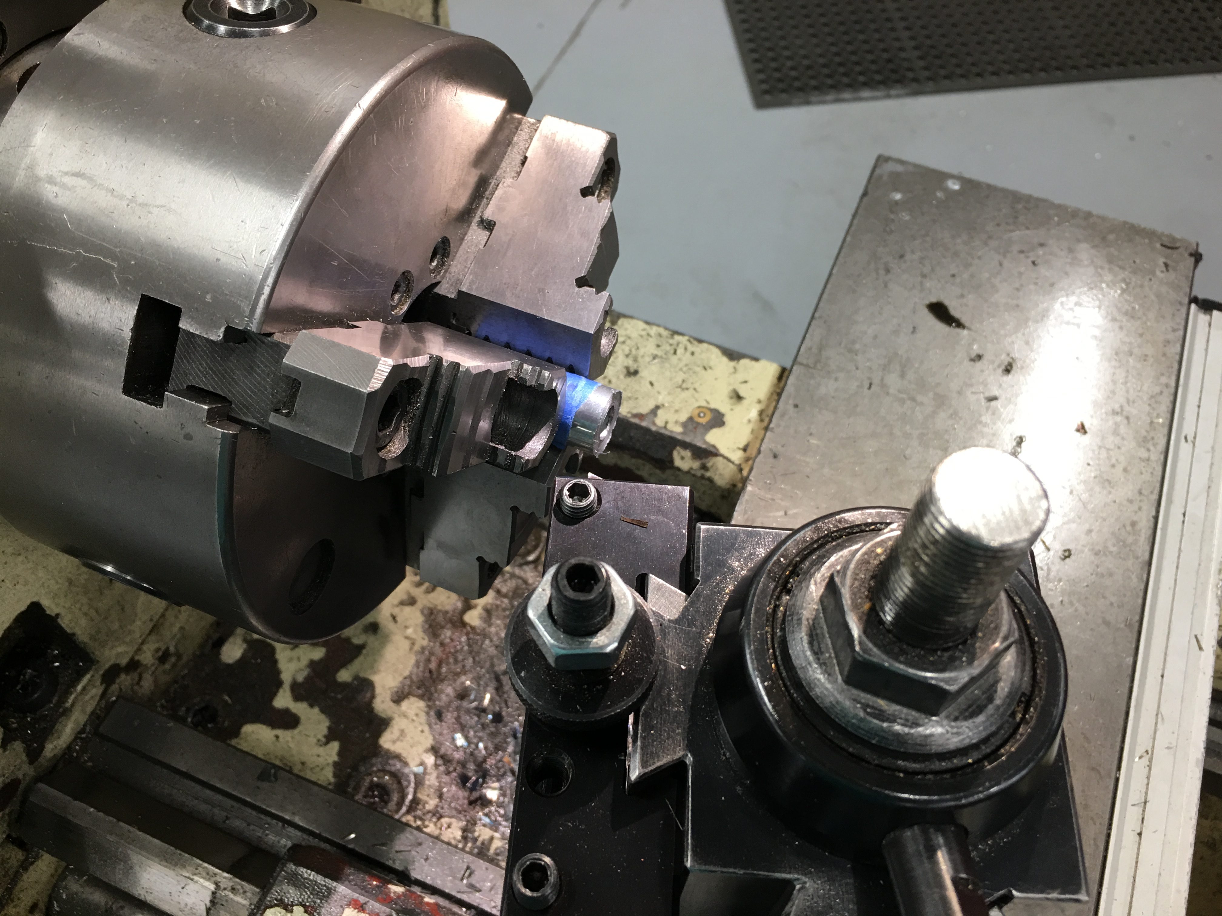
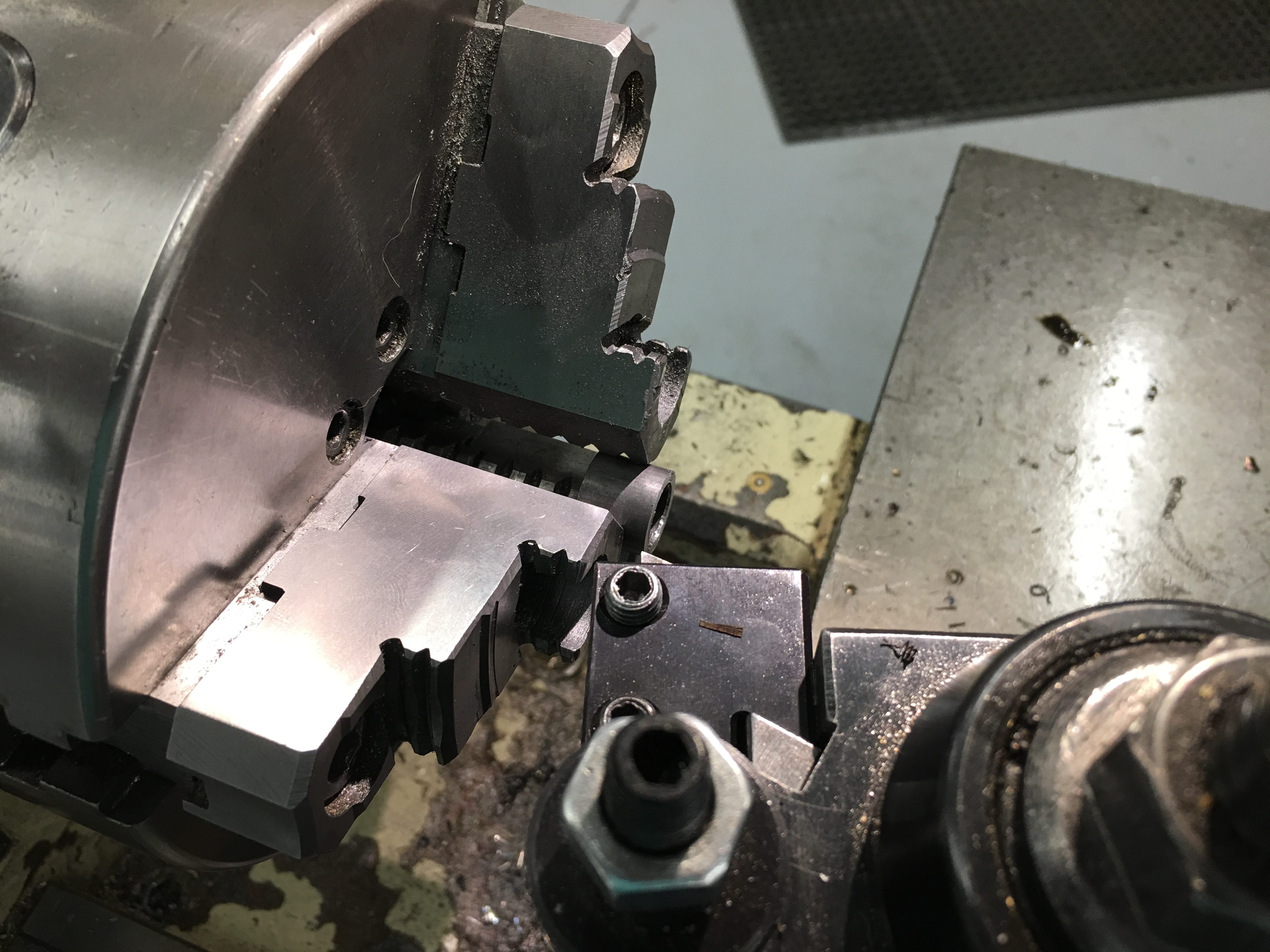
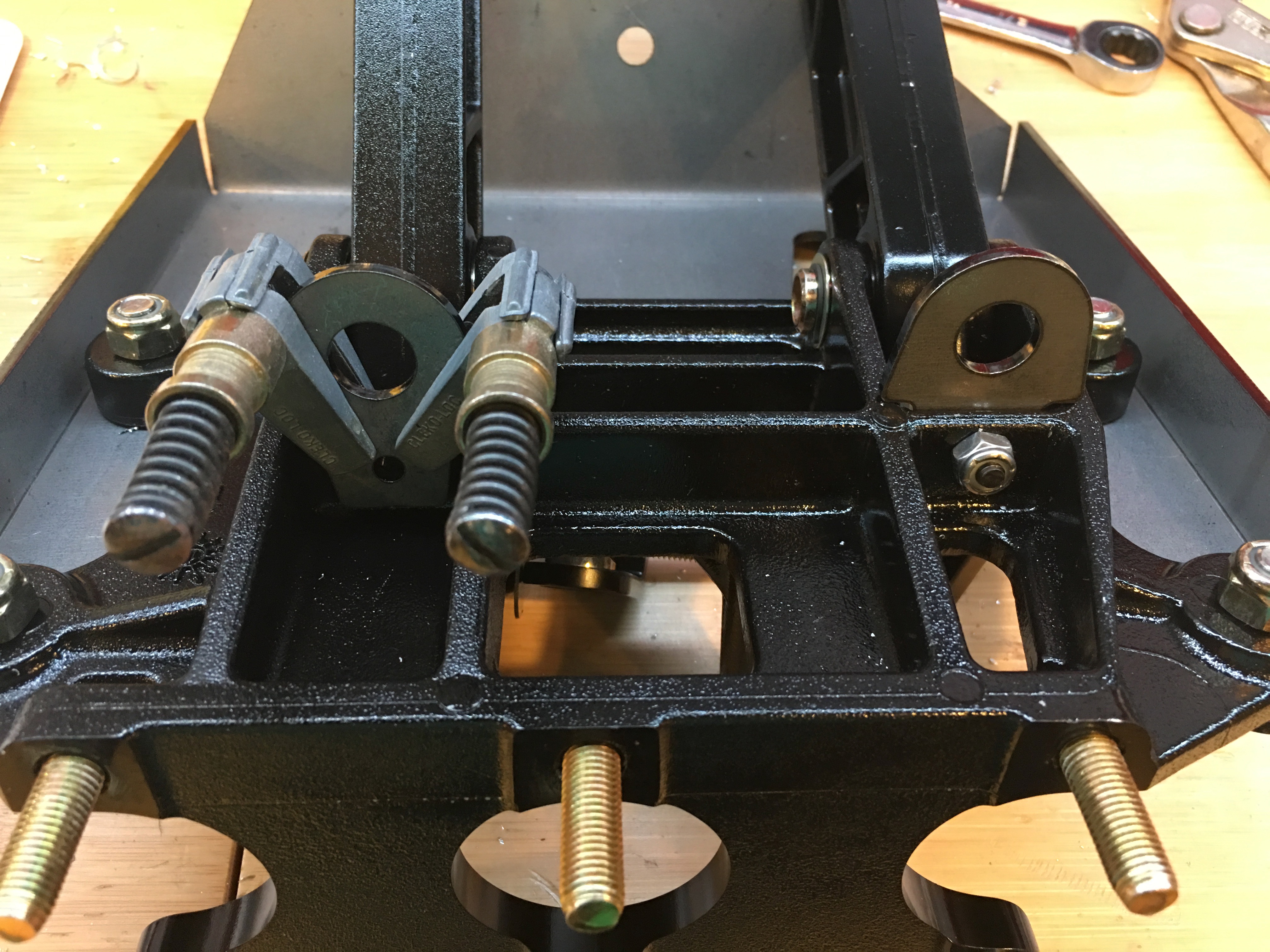
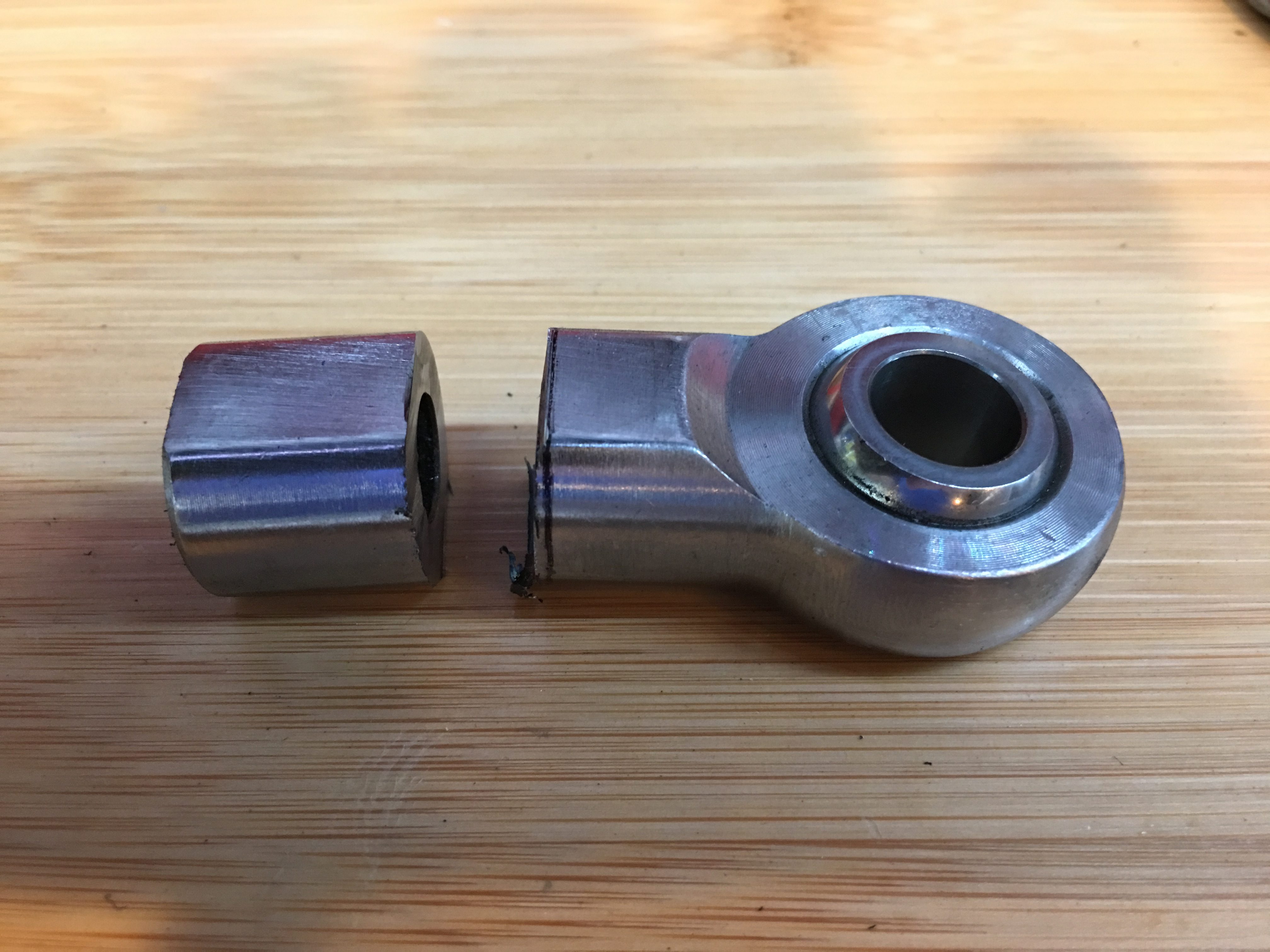
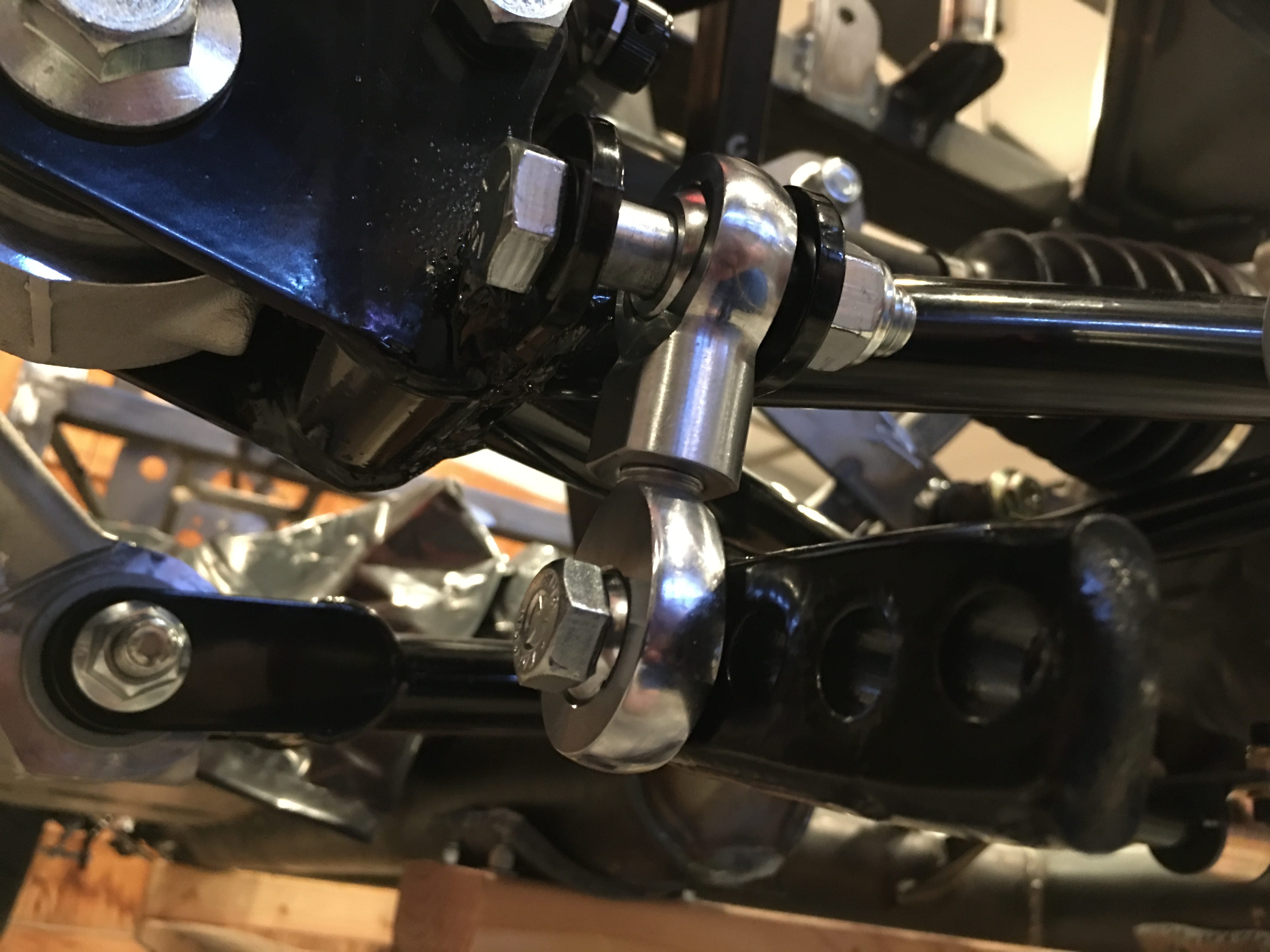
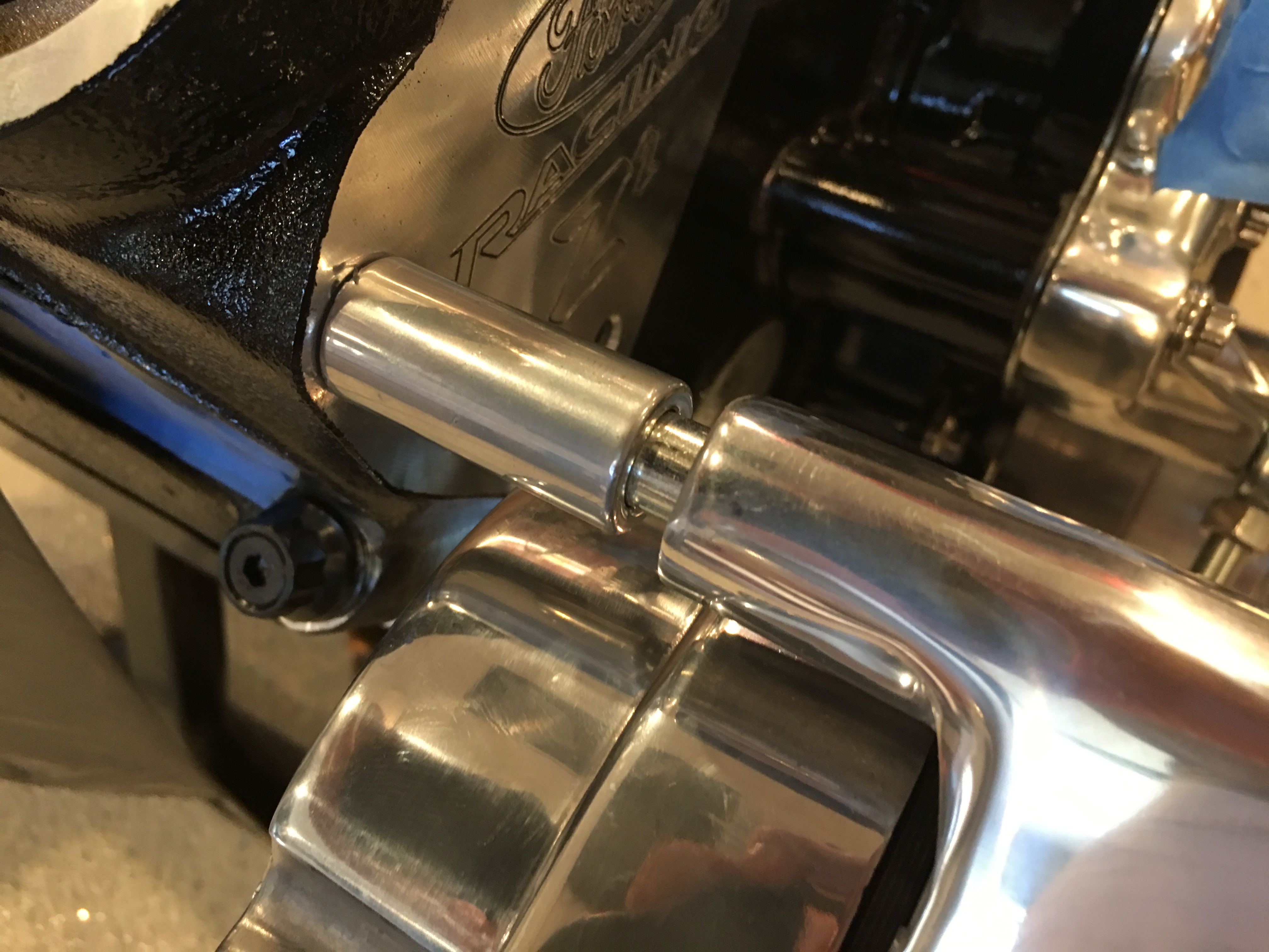
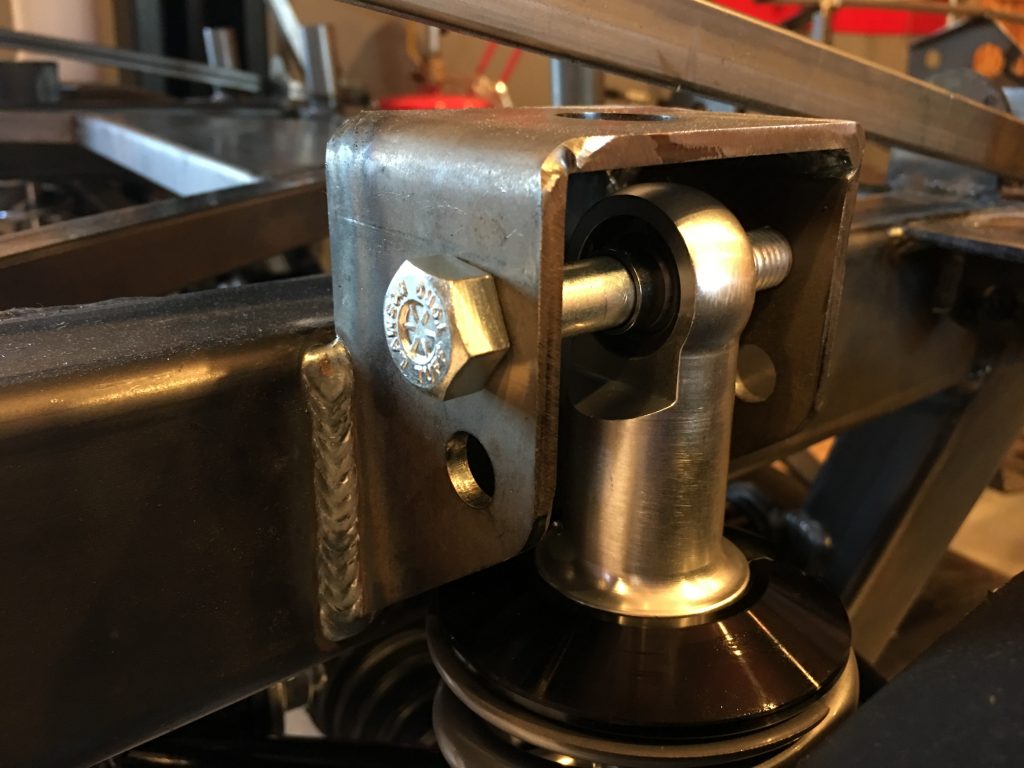
With the shocks installed, I started working on the sway bars. The rod end bearings are too long and need to be cut down until only 1/2″ of threads remain.

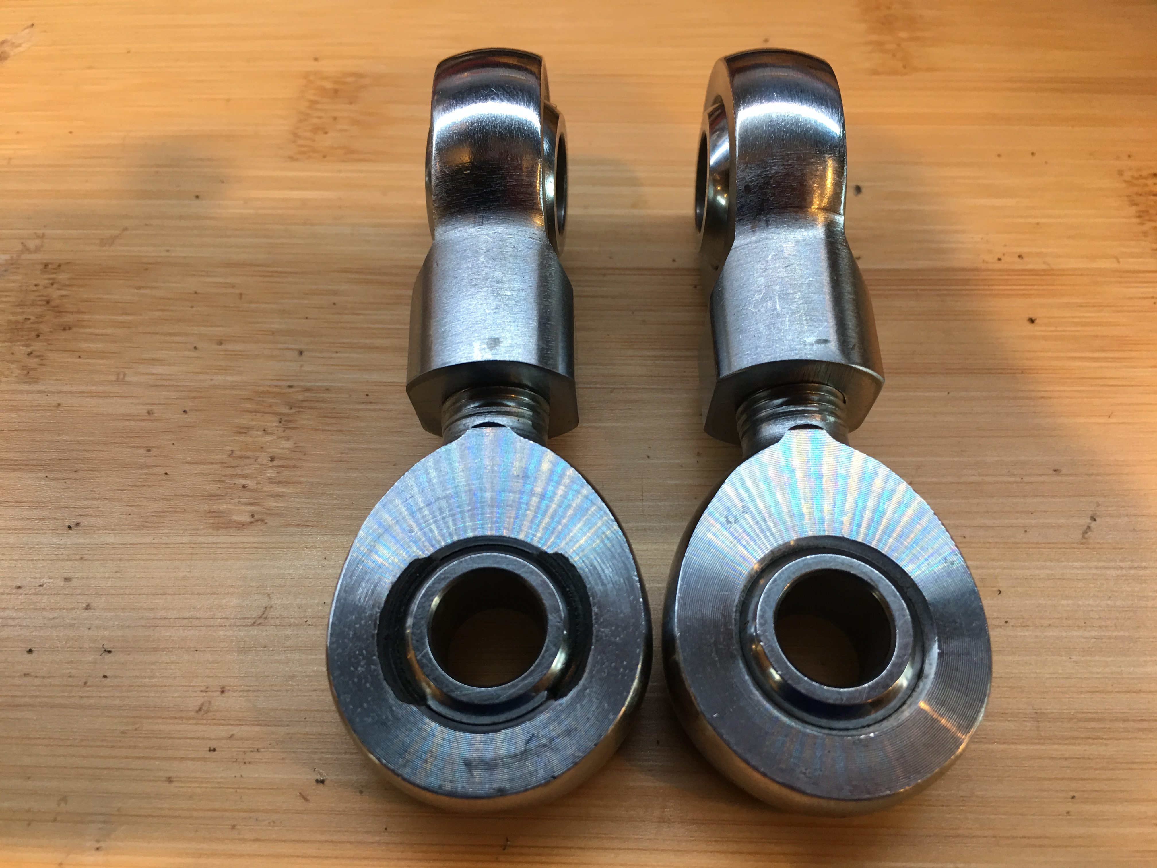
After trimming both the male and female rod end bearings for the front sway bars, they’re threaded together until they’re basically bottomed out and the bearings are 90º apart.

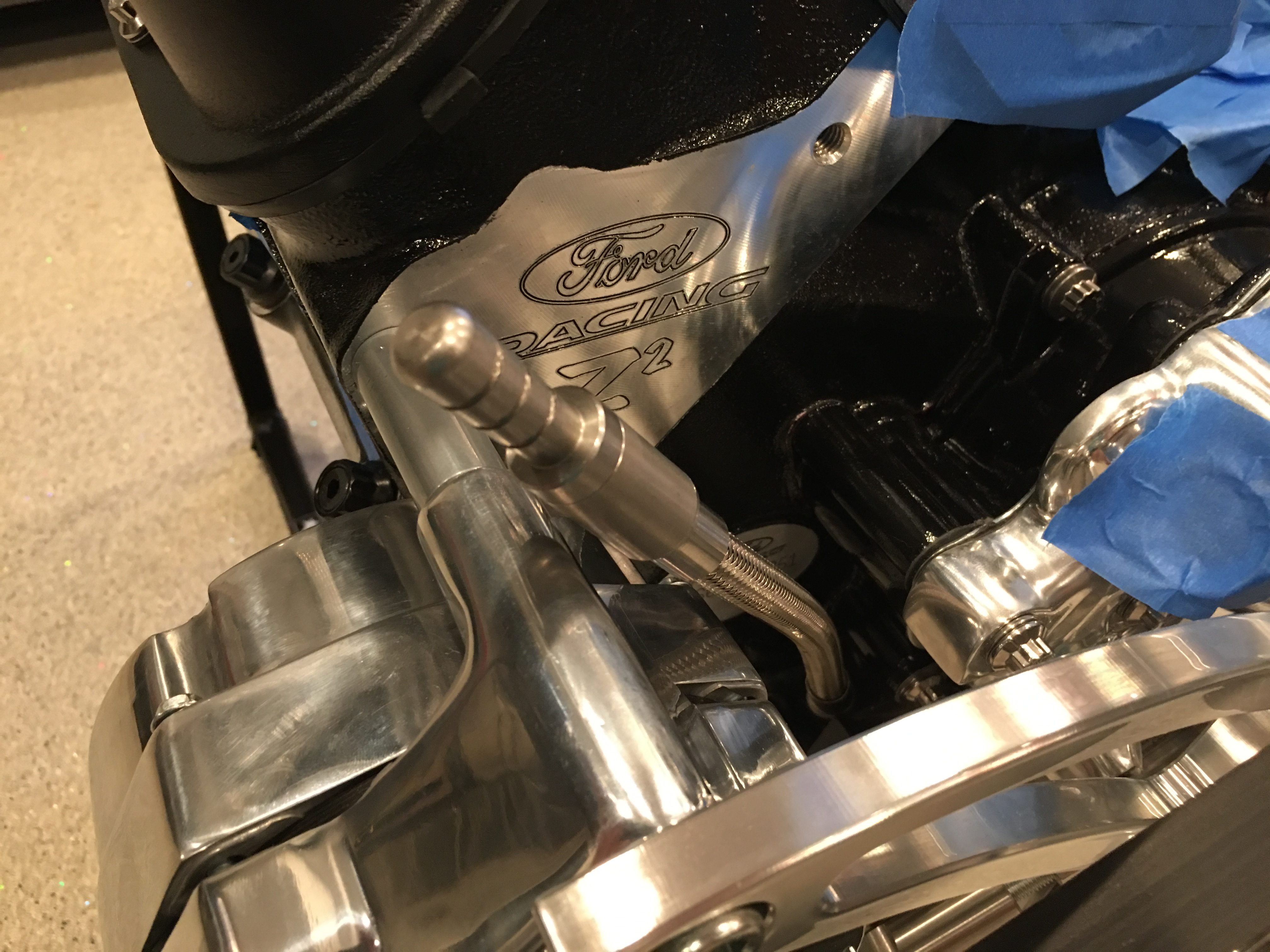
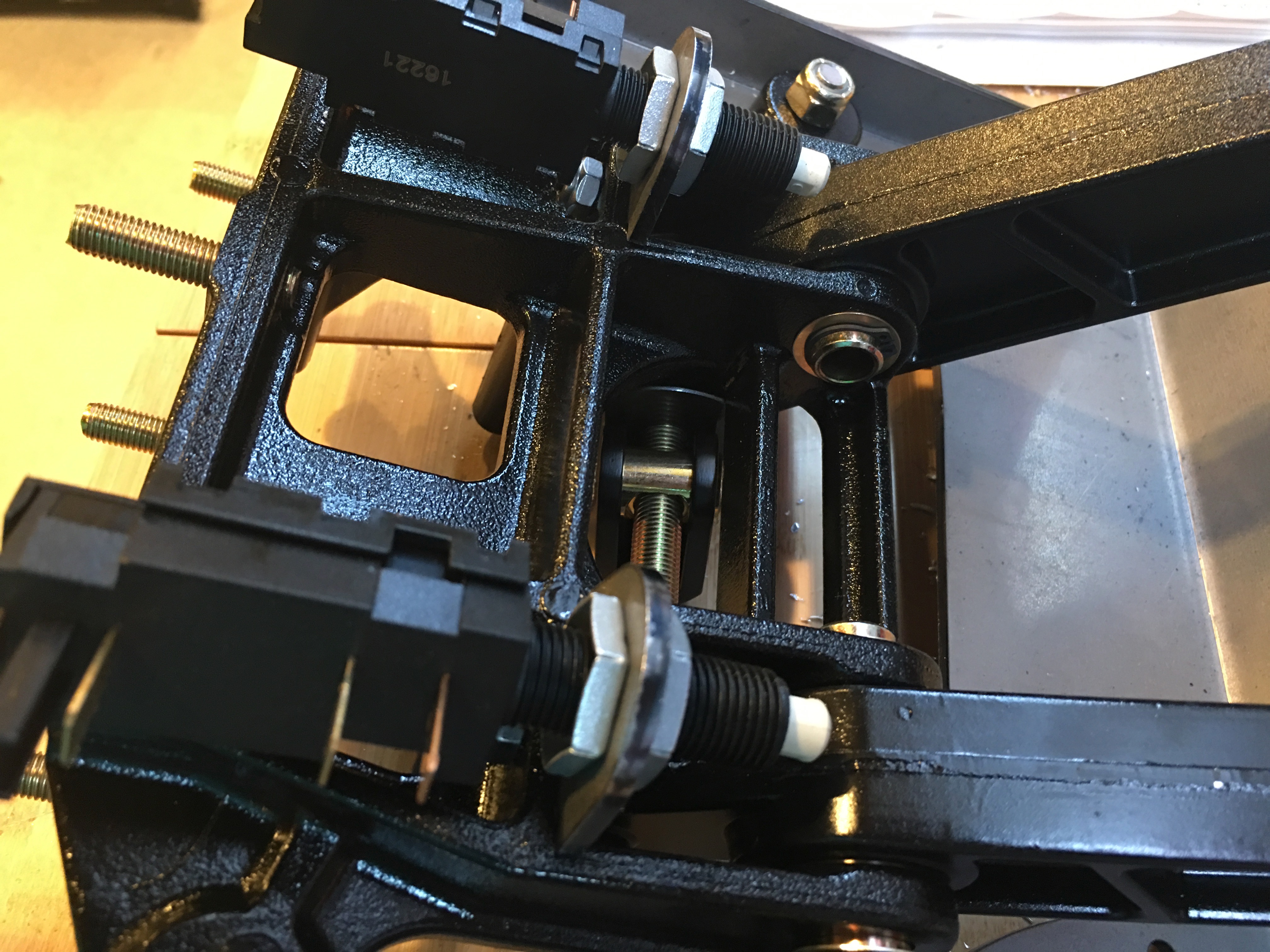
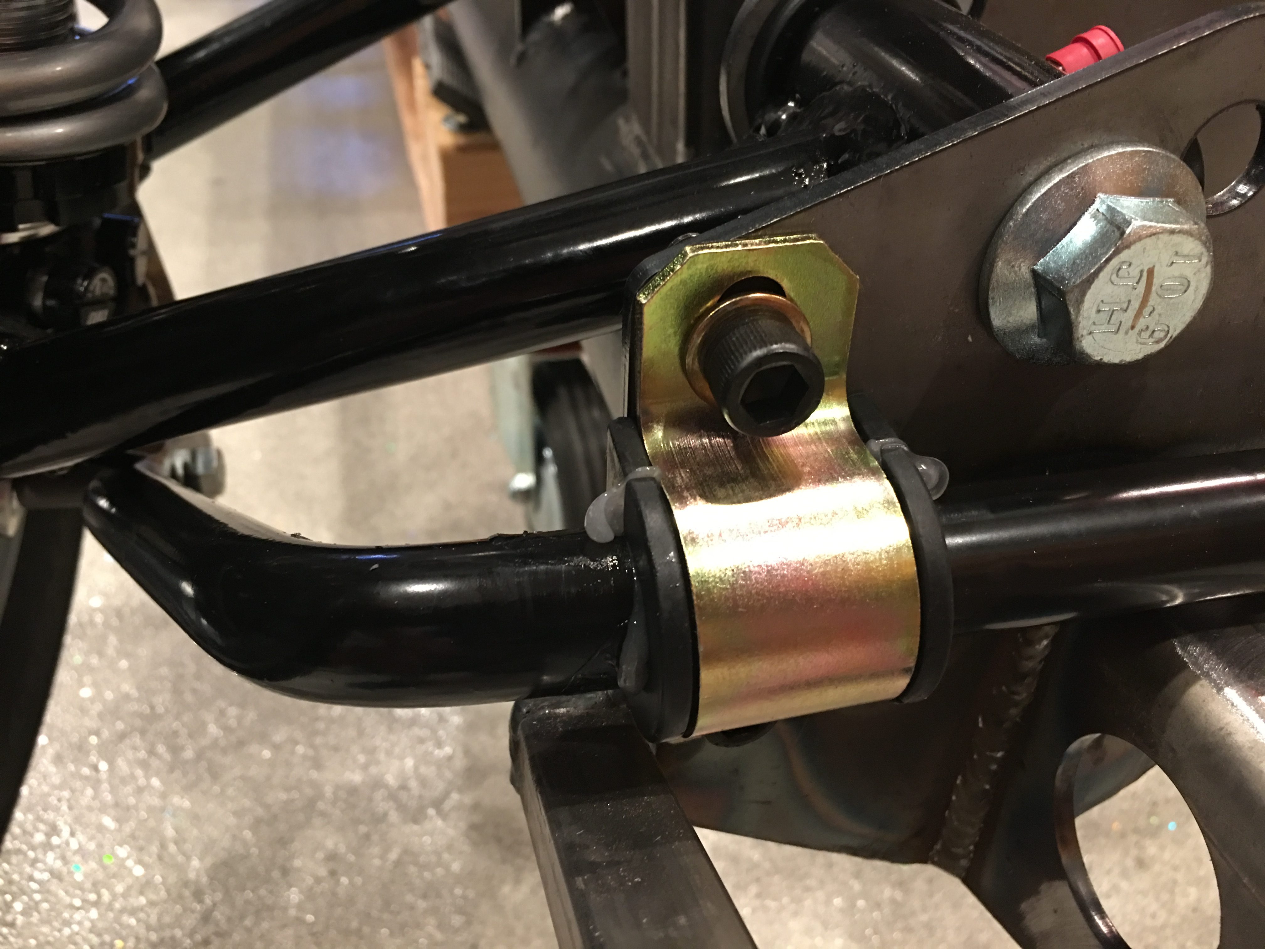
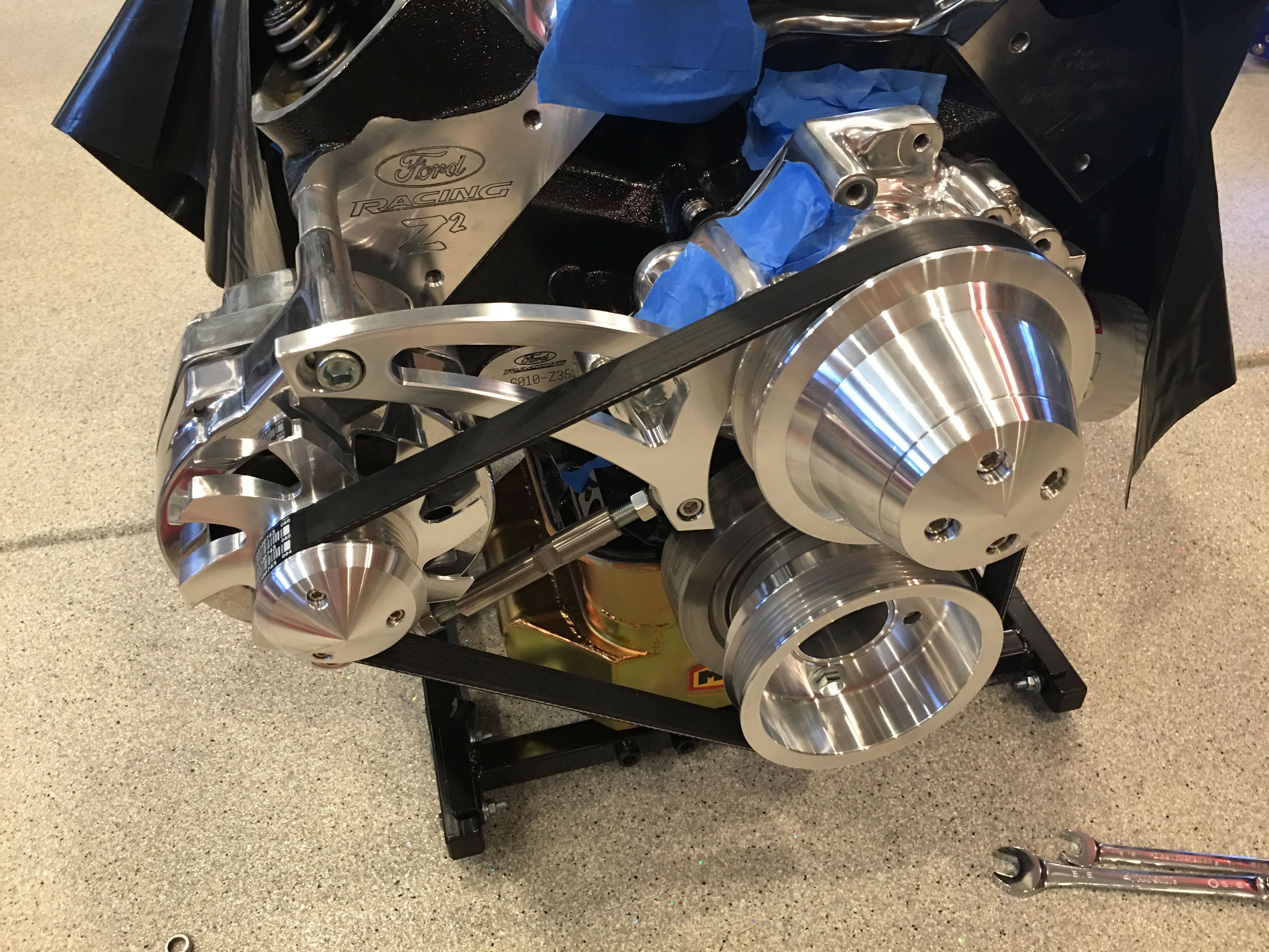
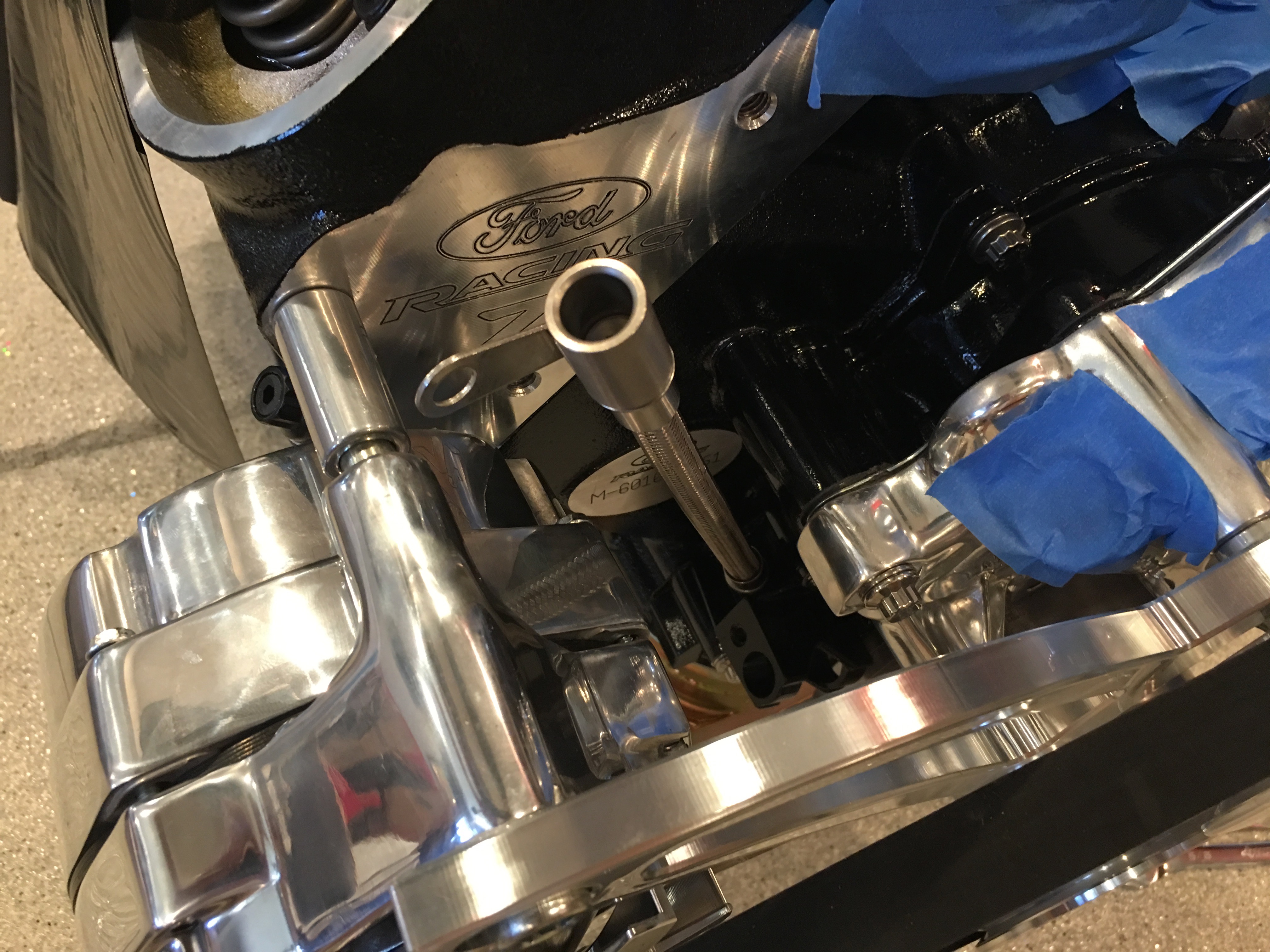
I installed the front sway bar to the mounting bracket.

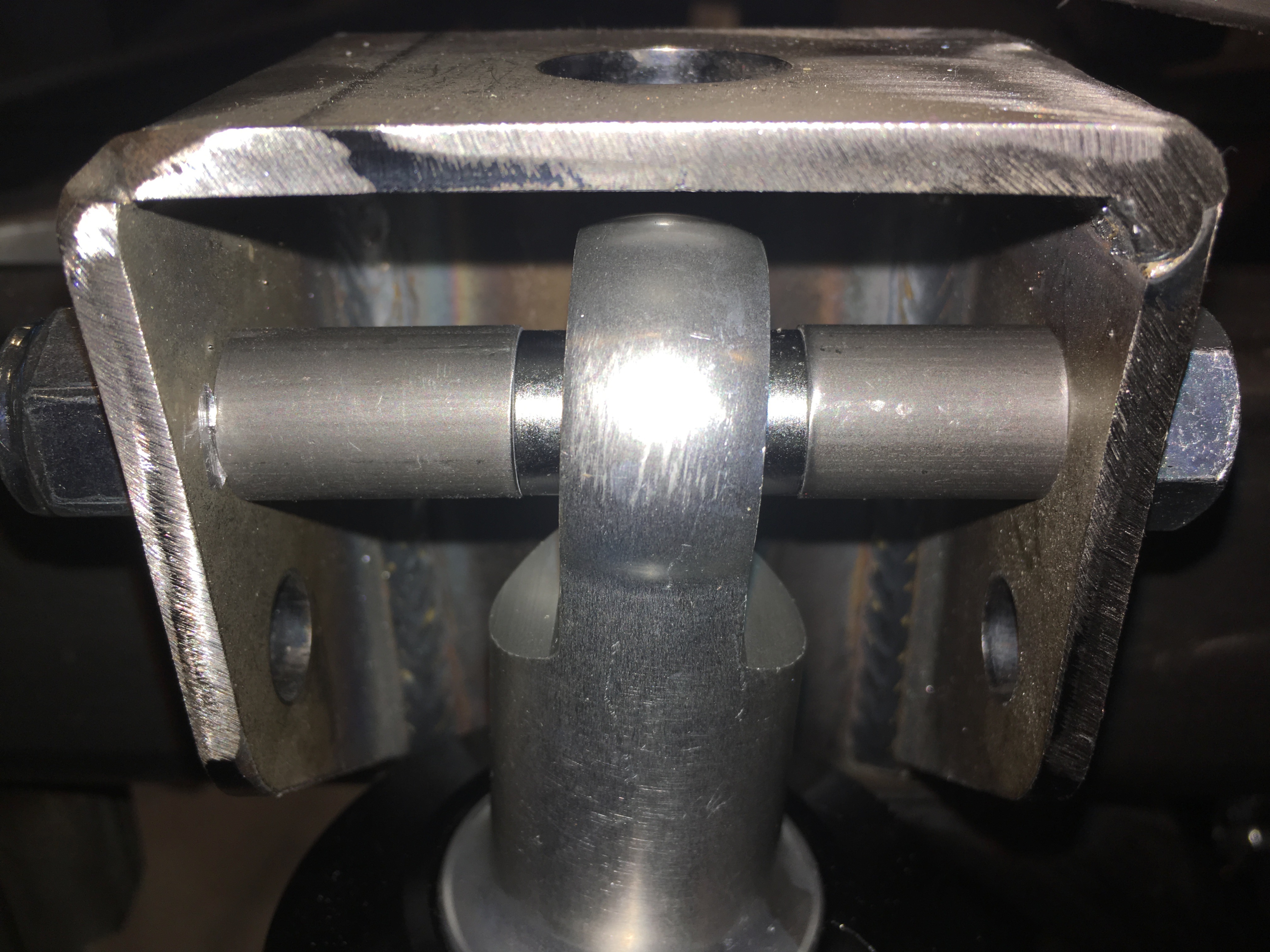
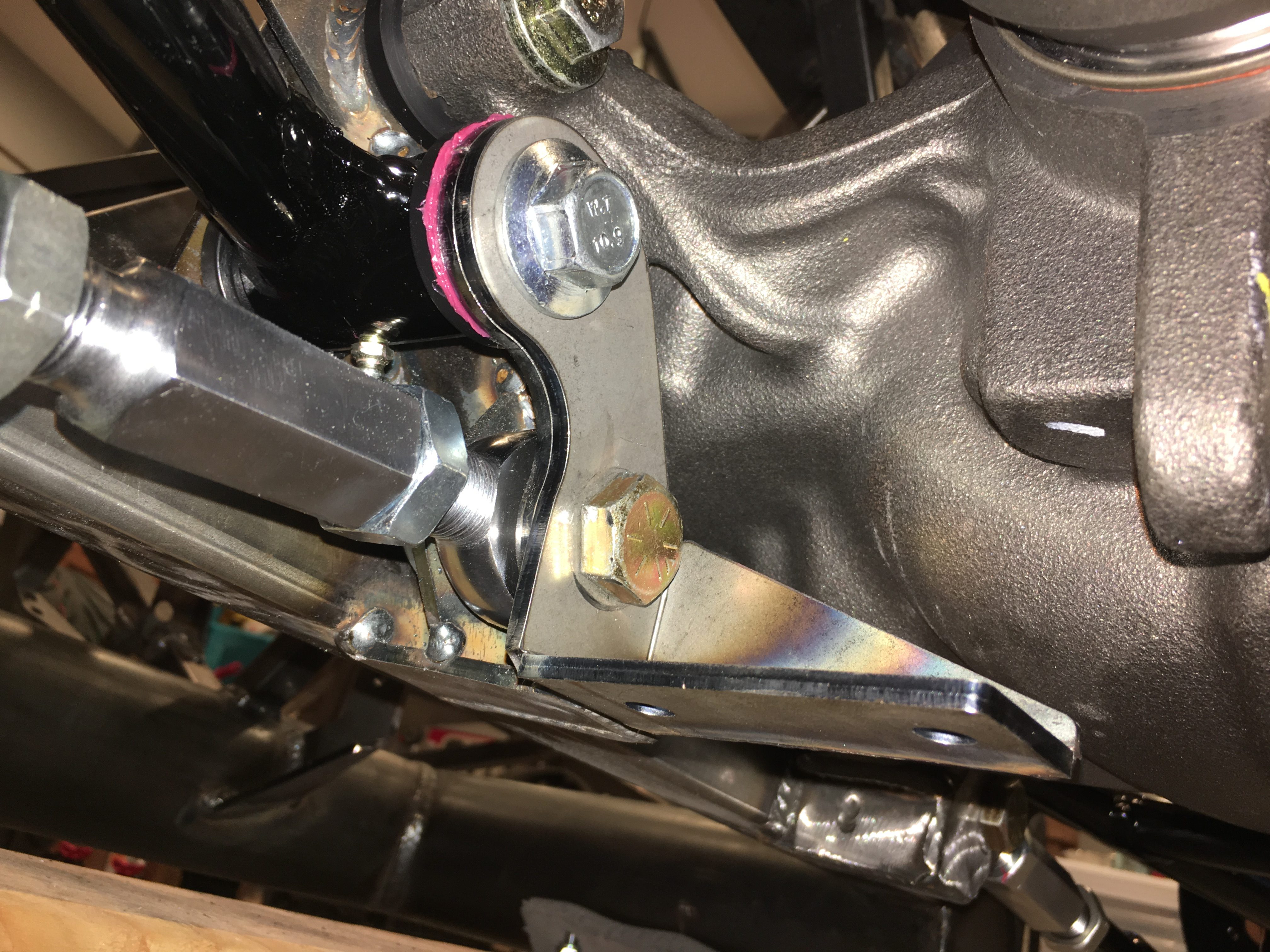
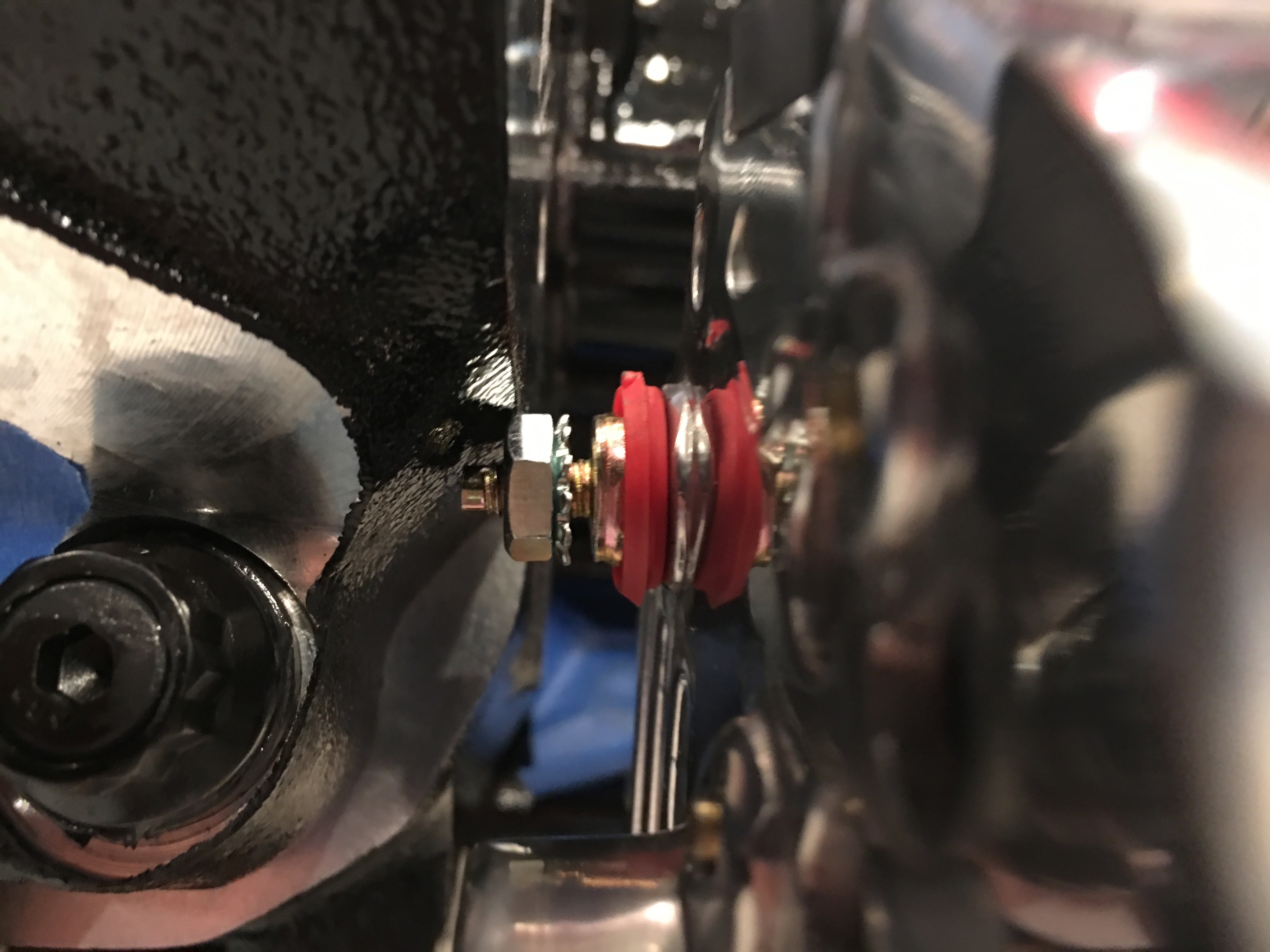
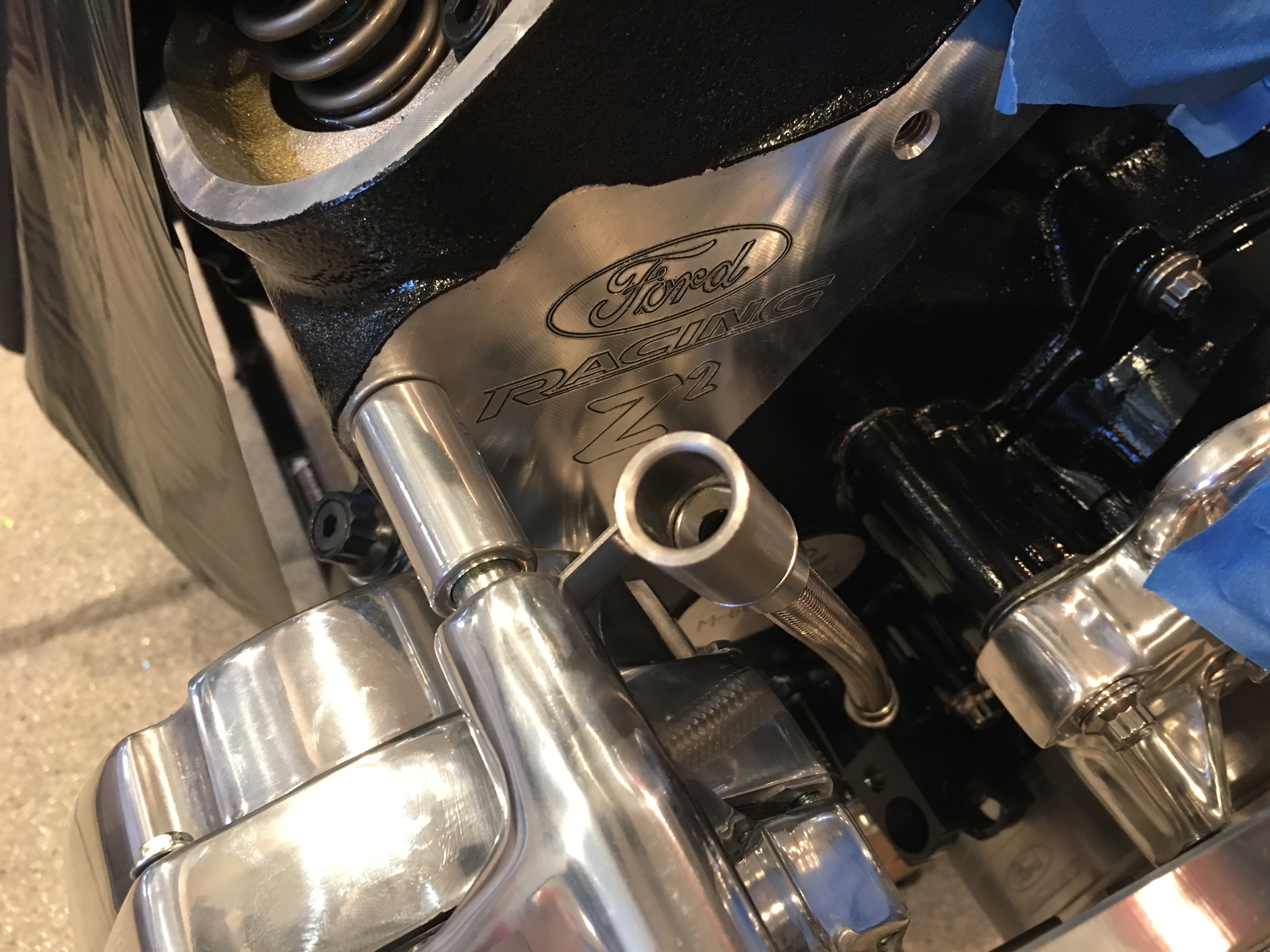
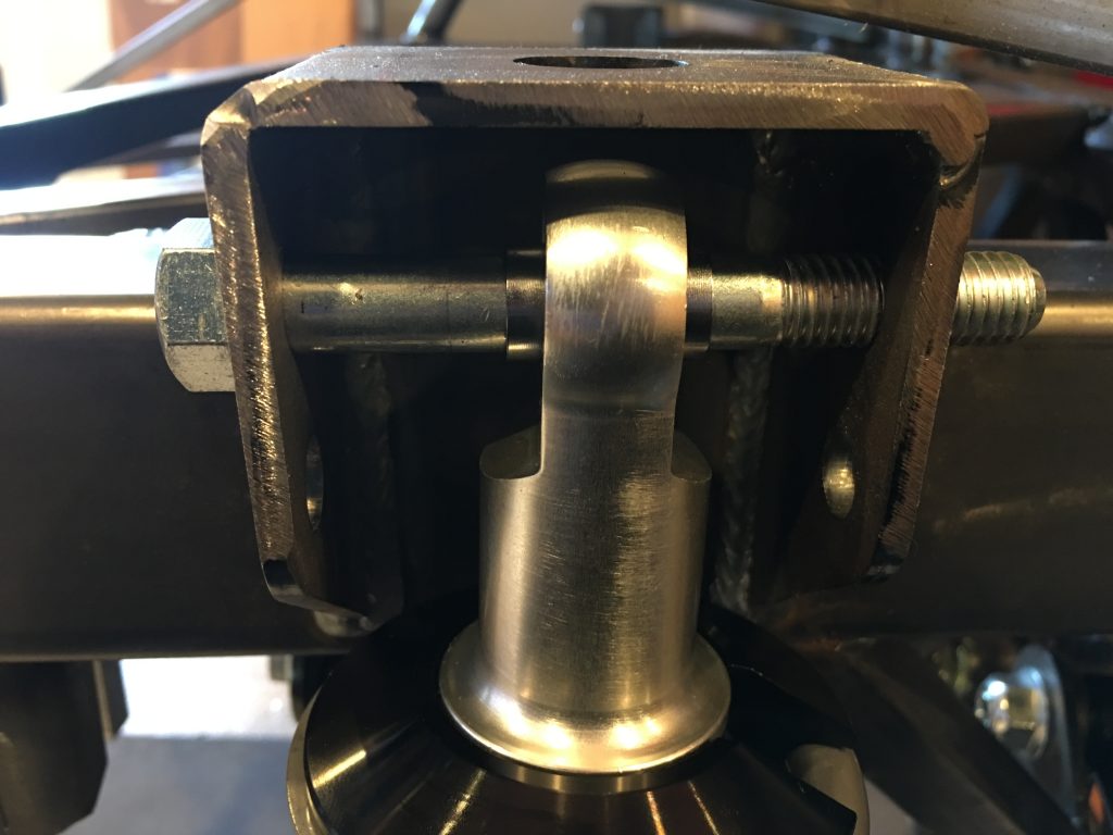
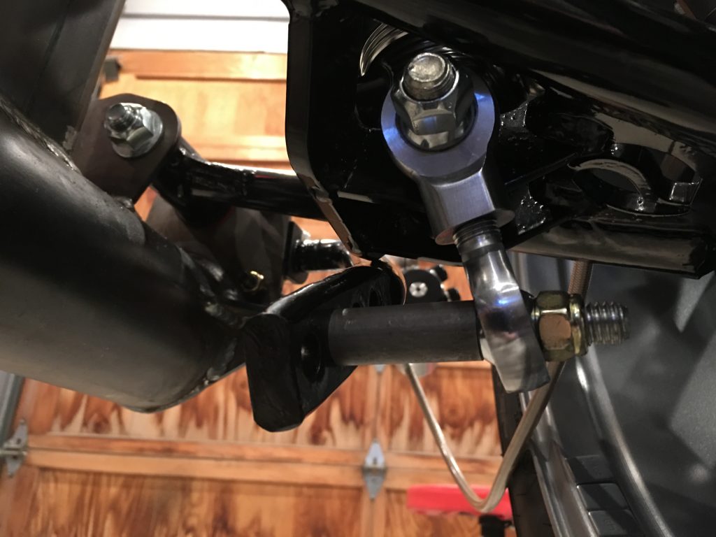
The ends of the sway bars are attached to the bottom of the shock mounts through the rod end bearings. The spacer seems too long here, but the bottom of the shock moves outboard as the suspension compresses. The rod end bearings should be basically straight up and down when the suspension is at ride height.

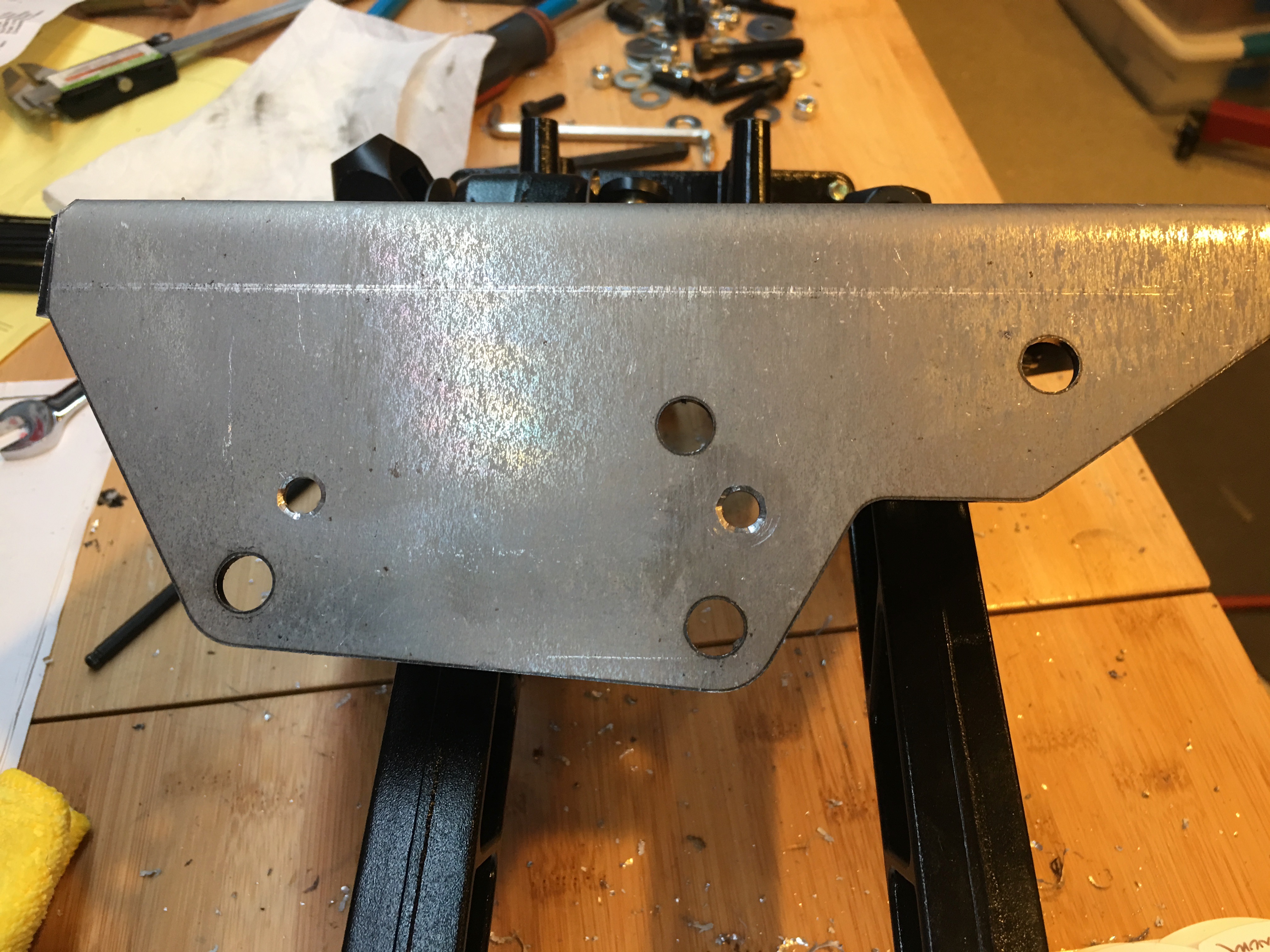
The rear sway bar mounts to a pair of brackets that are bolted to the chassis using the same bolts that hold the toe arms and the forward end of the lower control arms. I really wish I had realized this when we did the initial assembly of the rear suspension.

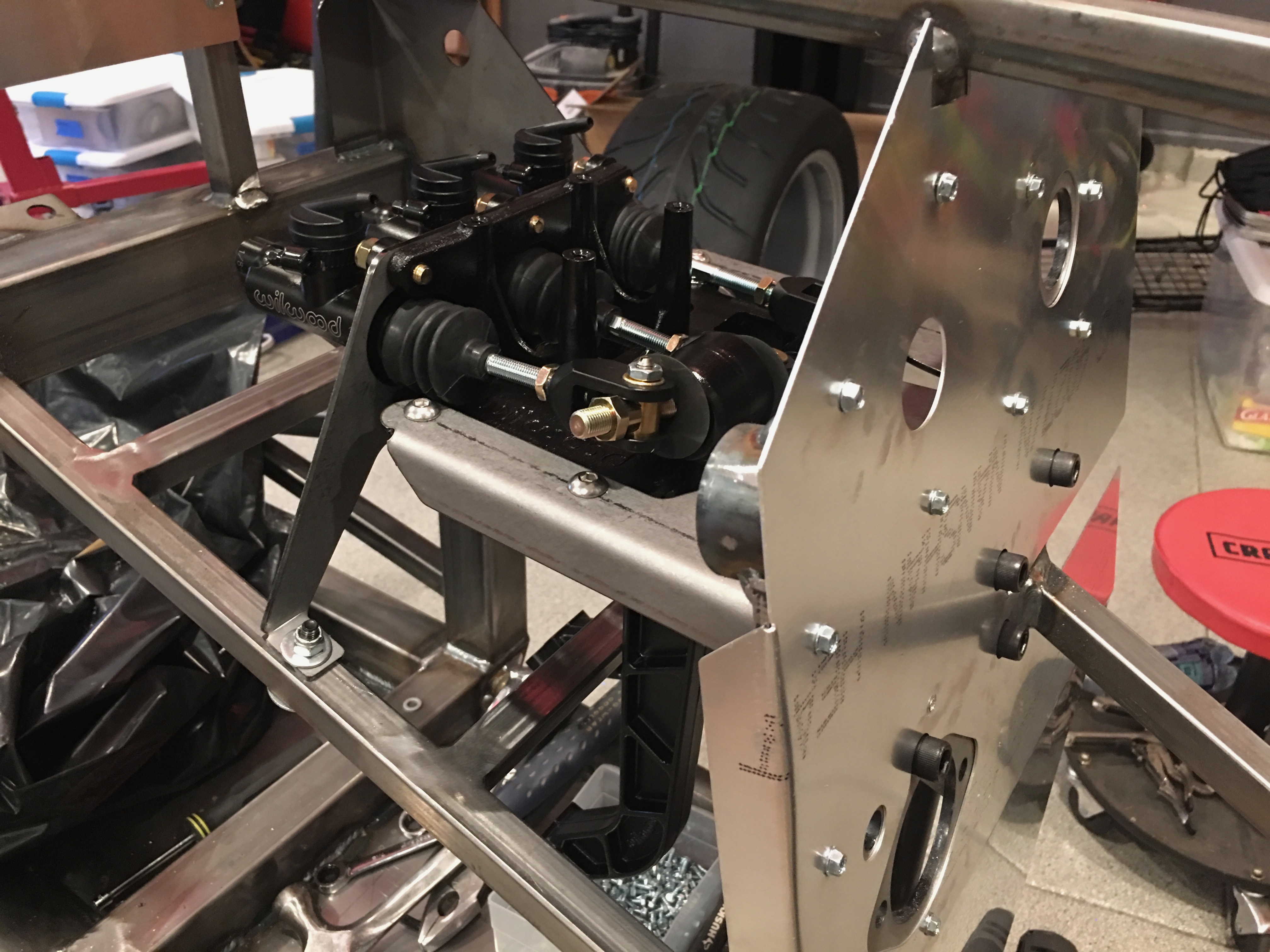
Once the bracket is bolted on, the sway bar can be bolted to it.

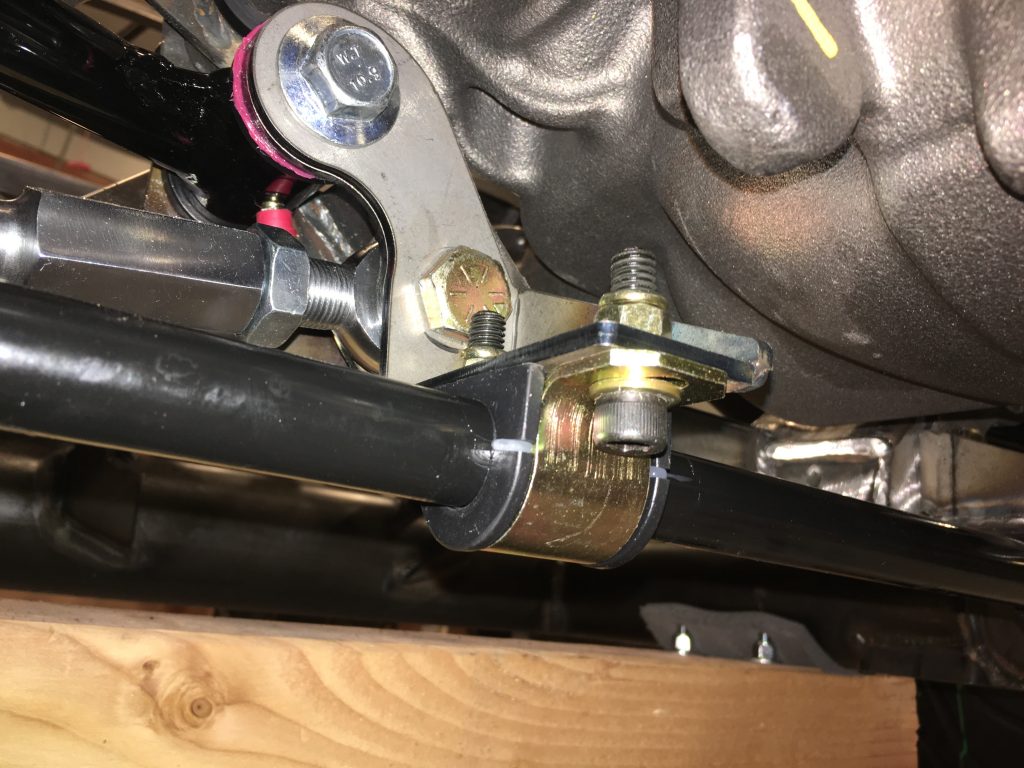
The other end of the sway bar is bolted to the lower control arm through a pair of rod end bearings. I need to fabricate some spacers to take up the extra space between the mounting ears.

Jenn Learning to Weld

We stopped by the Miller booth and Jenn tried her hand at MIG welding. She was super enthused to try out welding. Have I mentioned how lucky I am to have such an amazing wife?

Jenn got the hang of it pretty quickly and the instructor let her weld for quite awhile since there was no one else waiting.

By the end, Jenn was laying down some pretty nice looking beads.

Factory Five at EAA AirVenture

My daughter Madeline and I flew into AirVenture yesterday and they parked us in homebuilt camping just a few hundred feet from the Factory Five trailer.

Jenn and I stopped by this afternoon and had a nice chat with Dave Smith and a few builders. This is FFR’s first year at Oshkosh, and I think it was a success for them. The booth had a fair number of people in it every time we walked by, and homebuilt plane builders are exactly the kind of people who would be interested in building cars.

Plated Fittings and Received New Bolts

The water pump came with a couple of brass fittings for the heater hoses. We’re trying to keep the engine all black and polished metal though, so I decided to try plating the fittings. I picked up the tin-zinc plating kit from Eastwood a few weeks ago, but haven’t had a chance to try it out.

The kit is pretty easy to use and took only a few minutes per part to plate. As you can see, the parts look much nicer now.

The parts come out of the plating solution like you see on the left. A minute or so with a dab of the metal polish that comes in the kit shines it up nicely.

The valve cover bolts that came with the ARP engine bolt kit weren’t long enough. Apparently they’re intended for use with a stamped valve cover and cork gaskets. We’re using cast valve covers with thicker rubber gaskets, so we needed longer bolts. ARP was nice enough to exchange them for me and they arrived today.

The engine is all sealed up now and looks much better too.

We also got an order from Summit with some 2″ 3/8″-16 bolts, so I swapped out the hardware store bolts for them. We also got a longer spacer from March Performance, but I need to trim it down to the right length.

Swapping Rear Struts

I spoke with the engineer at QA1 about the fit in the back and we decided to swap the D4501 shocks for D4401 shocks. The D4401 is 1.5″ shorter and only has 3.875″ of travel (vs. 5.25″ on the D4501). To move the shock up to the upper mounting hole, we’re going to swap the upper eyelet for a 9036-196 which has an extra 1″ of length. Since the upper hole is exactly 1″ higher than the lower hole, this will end up leaving the upper spring seat exactly where it is in the picture below.

This will also mean that the ride height adjustment nut will be near the bottom of the adjustment range using the same spring. To correct this, we’re going to swap the 10HT250 (10″) spring for a 9HT250 (9″) spring. This should put the adjustment nut closer to the middle of the adjustment range at the recommended ride height.

I also measured for the spacers we’ll need on the front shocks. The eyelets are wider on the QA1 shocks than the Konis that come with the kit, so I’ll need to make custom length spacers to center the shocks in the mounting brackets.

March Performance Pulley Kit

I ordered the March Performance 30380 pulley and bracket kit along with a 140A polished alternator. I probably don’t need anywhere near 140A of power, but the cost delta between the 100A and the 140A was small. These are really nicely machined pieces and everything except the alternator has been powder coated with clear. They don’t match exactly, but they all look good together.

The combination of the water pump we’re using and the Ford harmonic balancer necessitated a 0.875″ spacer between the harmonic balancer and crankshaft pulley. I made this determination without any of the parts on hand and happily it was exactly right. I bought a couple of hardware store bolts to attach this for now, but I have some 2″ ARP 3/8-16 12pt stainless hardware on the way.

When I first tried to mount the alternator, the output stud contacted the side of the cylinder head.

Fortunately, Tuff Stuff alternators can easily be reclocked. I removed the four bolts holding the case halves together and rotated the front case 180º and reassembled it.

Now the output stud has plenty of clearance. I’ll see if this puts it in an optimum location as the build progresses. I can always reclock it if another location makes more sense.

The tensioning arm attaches to a small bracket that bolts to the lower mounting lug. The other end of the tensioning arms bolts behind the alternator mounting bracket.

The spacer that March Performance ships is too short. I have a longer one on the way.

To ensure everything is lined up correctly, I installed the belt and tightened the tensioner a bit. It looks like it’s basically perfect. I really like this mid-mount position for the alternator (as opposed to the top-mount which has the alternator sitting on top of the pivot bolt instead of hanging below it). This leaves the water neck completely unobstructed and is totally out of the way of the timing chain cover mounted oil dipstick. It also leaves the ends of the cylinder heads exposed. Since we went to the trouble of painting the engravings, I really wanted these to be visible.

As you can see, there is a straight shot down to the hold in the timing chain cover for the oil dipstick tube.

It looks like a really convenient mounting spot for the upper end of the dipstick tube is the pivot bolt for the alternator. I’ll confirm with Jenn, but these doesn’t block anything else and leaves the tube about as close to straight as you can get it. I’ll install this with some RTV on the bottom once Jenn’s back in town.