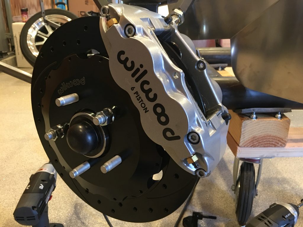
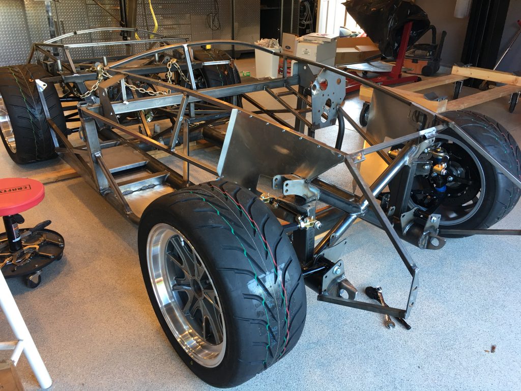
I got started this morning on the front brakes which are a little more of a pain than the rears. The bracket that holds the caliper on doesn’t fit the FFR spindles without some modification. After searching the forums, the consensus is to grind the spindle until the bracket fits. The only interference is with the upper mounting hole on the bracket, but that part of the spindle is super thick. I only needed to remove about 1/16″ of material, so strength is not compromised.
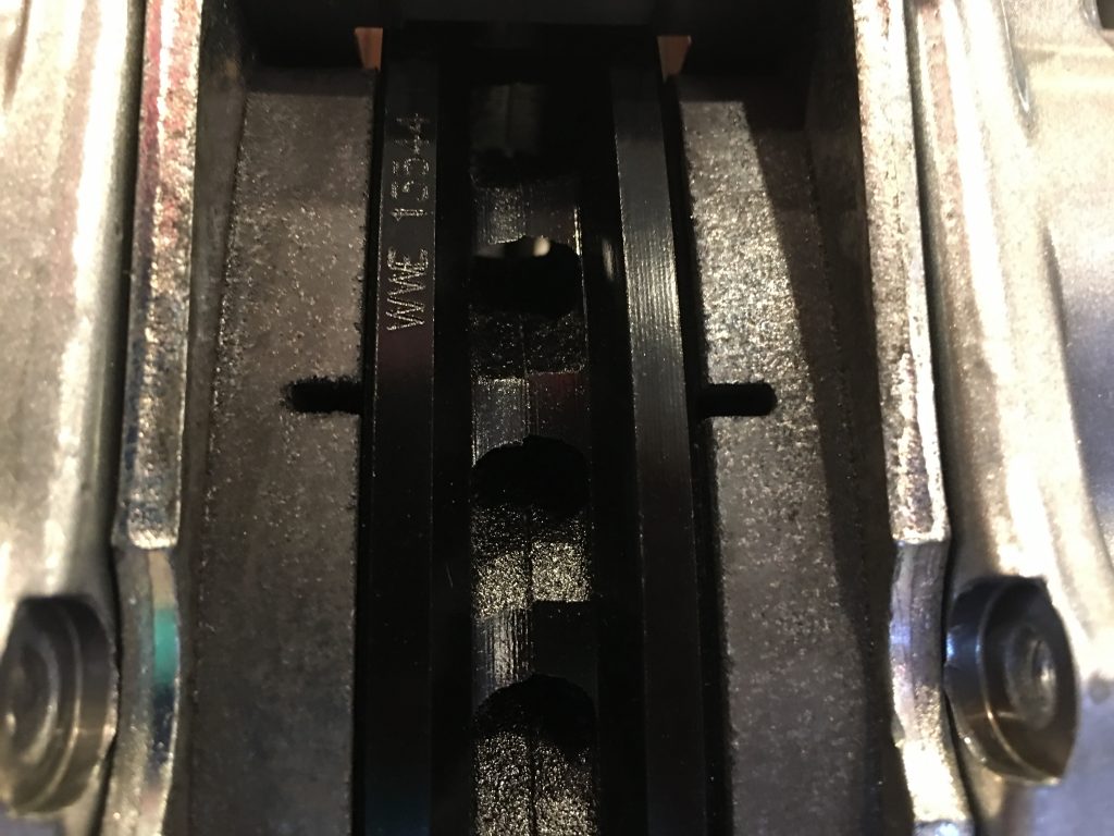
With the Big Brake kit from Levy Racing, there is very little clearance between the wheel and the caliper, so the caliper needs to be biased inboard a bit. The instructions from Gordon are to shim the caliper inboard enough that the outboard pad can just barely be inserted. I ended up using about 0.150″ thick shim to space the mounting bracket inboard which lets me insert the the outboard pad with about 0.012″ of clearance. Even though the gap is greater on the inboard side, this will even out the first time the brakes are applied. Since there are pistons on both sides, the inboard pistons will just extend a little more.
Wheel spacers are used to shim the wheels outboard about 0.090″, but that still only leaves about 0.040″ between the back of the spokes and the face of the caliper. Since the calipers are rigidly mounted and don’t float like most OEM calipers, this is more than sufficient clearance.
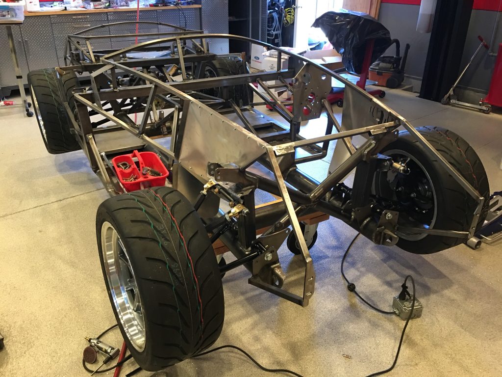
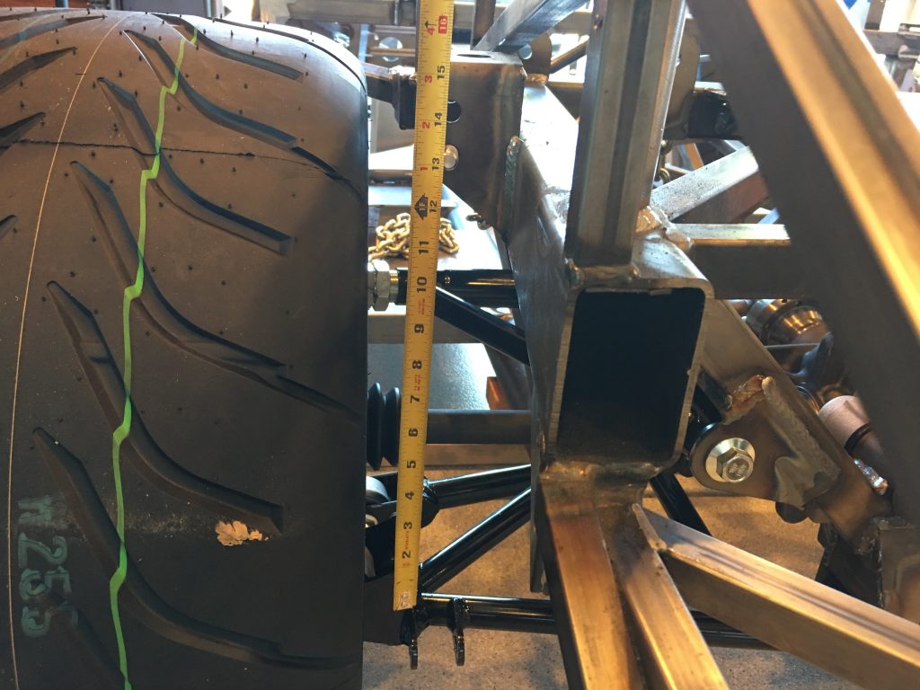
The reason I wanted to get the wheels on now is that I need to measure for the struts. The manual says the chassis ride height should be 4.5″ from the ground to the bottom of the 4″ main tubes. I laid down three 2x4s and then set the chassis down on them.
I did the same thing in the front and then adjusted all four control arms to put the wheels at zero camber.
I put a couple of bolts in the upper and lower mounting brackets and measured for the ride height distance. It’s a little unclear whether the upper end of the shocks should bolt into the upper or lower hole.
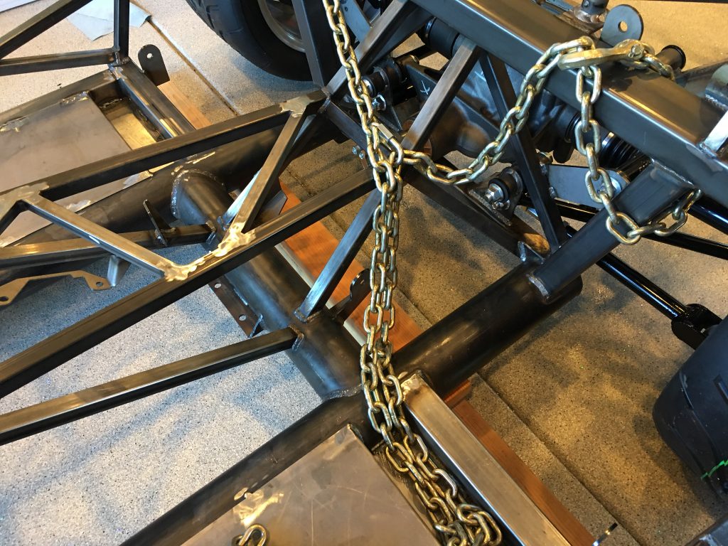
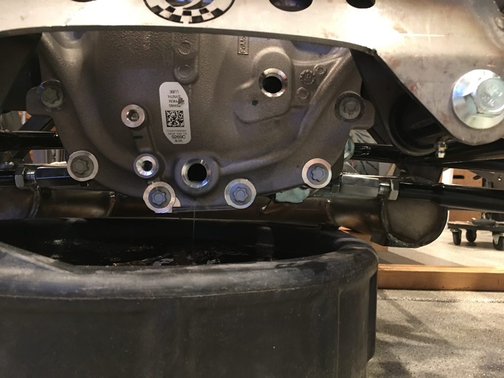
I drained the differential in preparation for filling it with new fluid.
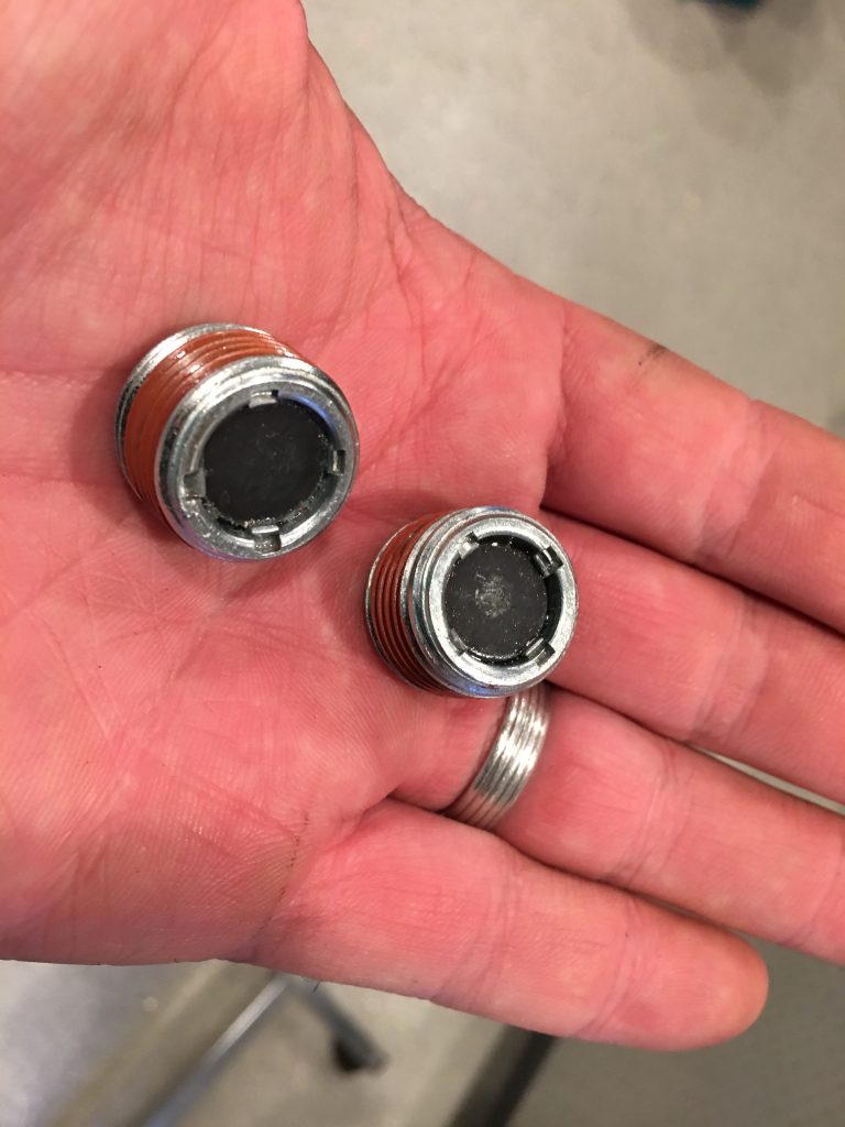
I was pleasantly surprised to see that both the fill and drain plugs both included magnets to catch any loose metallic particles floating around in the oil.
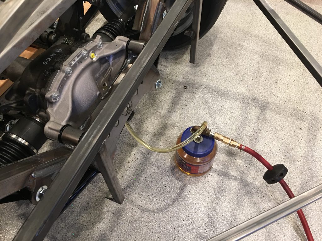
My dad brought over this contraption he made to fill transmissions and differentials. It hooks up to a compressed air source and then has a needle valve to control the air pressure in the canister. There is a pickup in the bottom of the canister that connects through a fitting to the tubing on the top. When pressurized, fluid is forced up the tube. The plastic canister can’t take much pressure, so it takes awhile to pump 2.5L of fluid up into the diff.

