Front Spindles and IRS

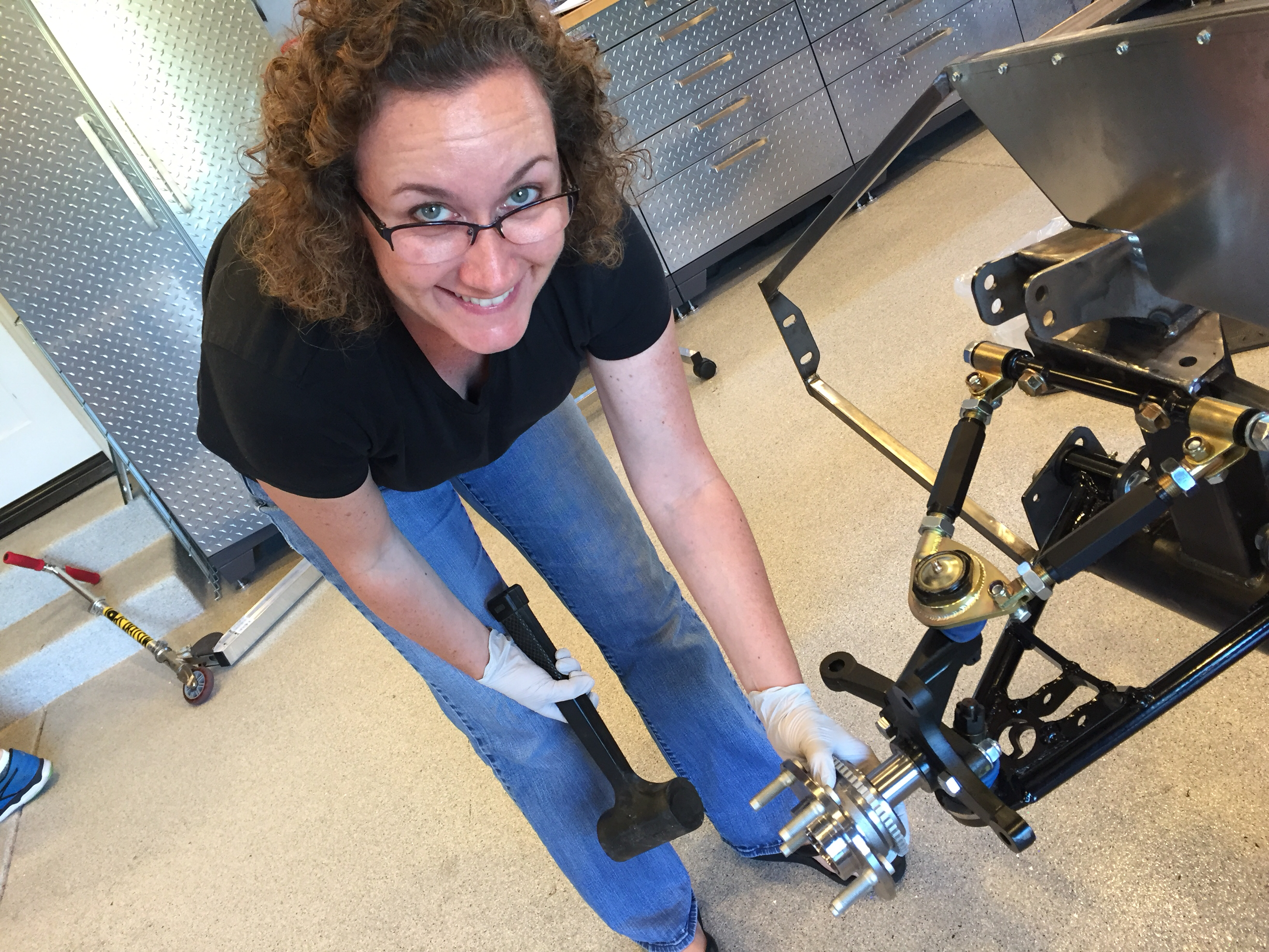
Jenn got started this afternoon installing the hubs on the front spindles. These only required some light tapping to get them on far enough for the nut to be engaged. Tightening the nut allow the hub to be pulled on the rest of the way.

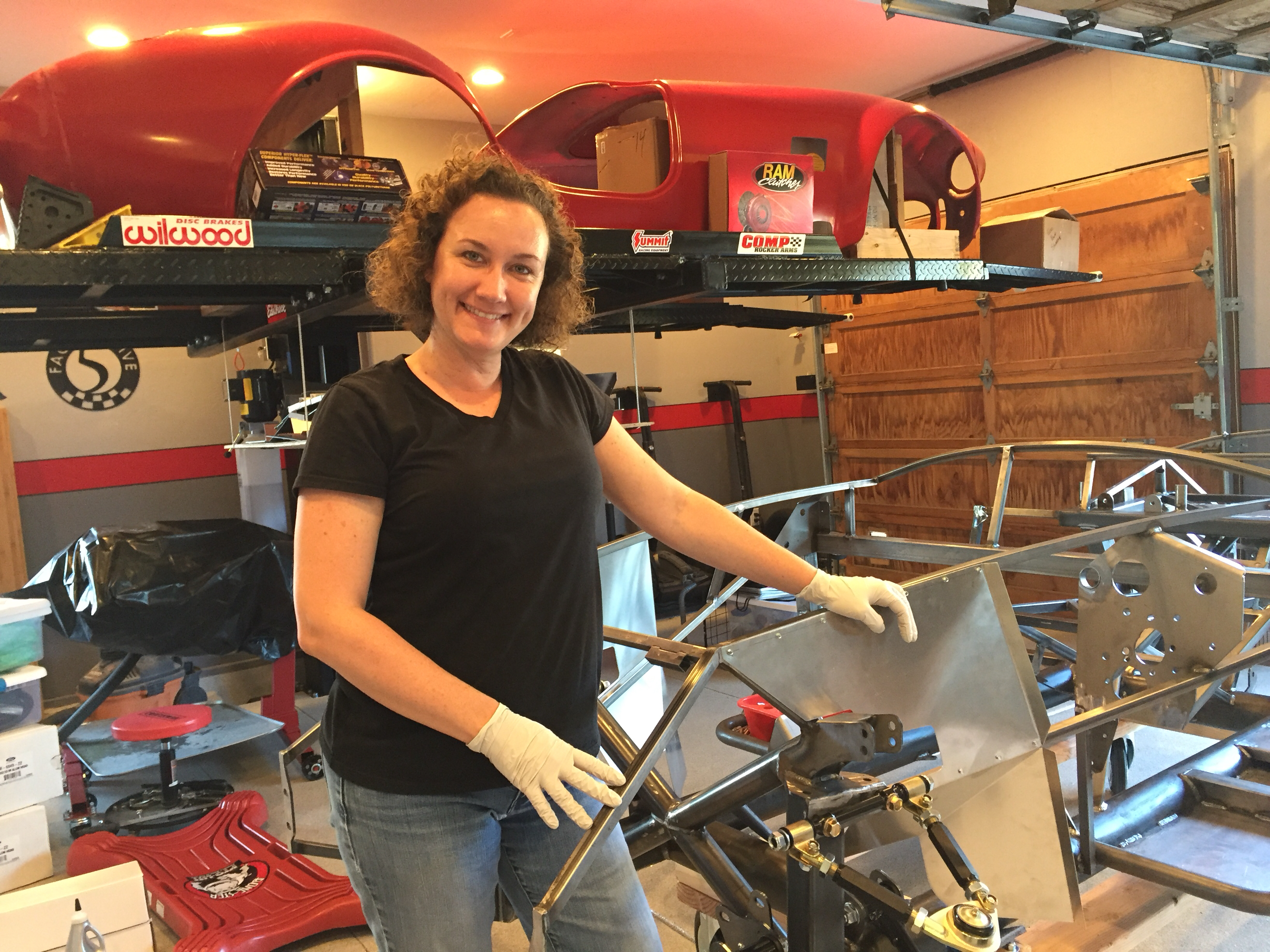
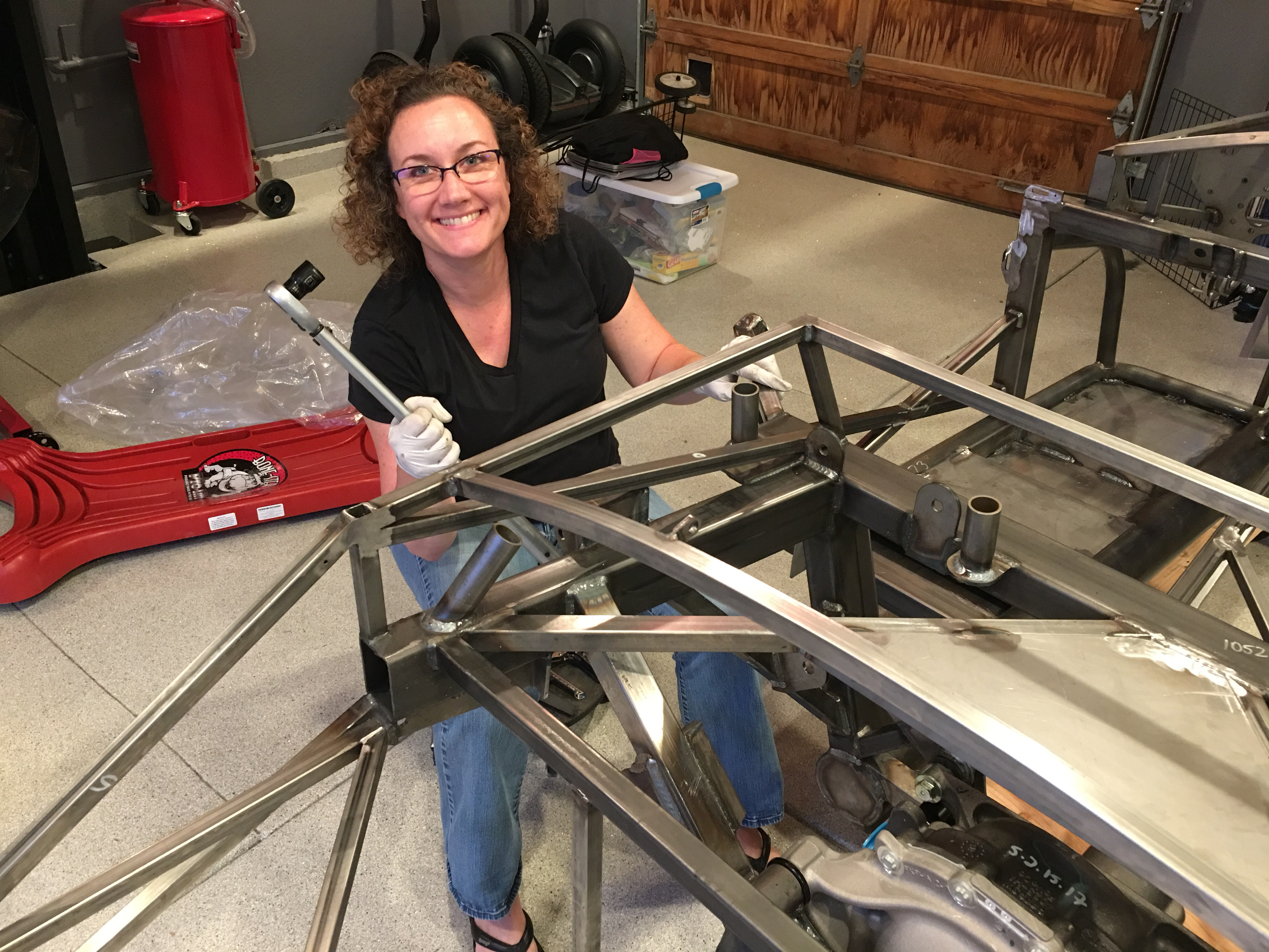
Jenn’s excited to finally get started on the car after a brutal work schedule over the past six months.

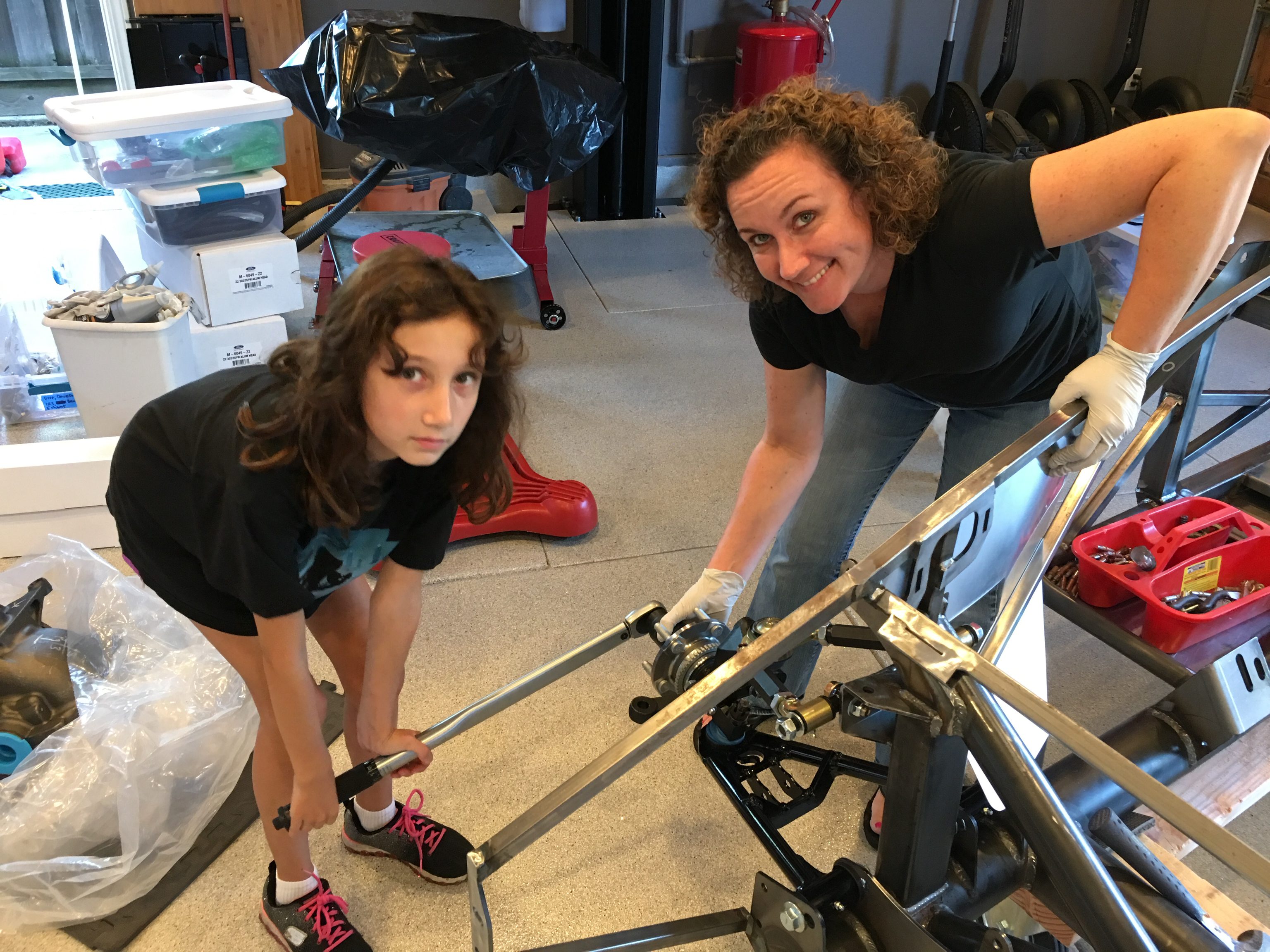
The kids wanted to help, so we had them tighten the axle nuts until they were too tight for them to turn.

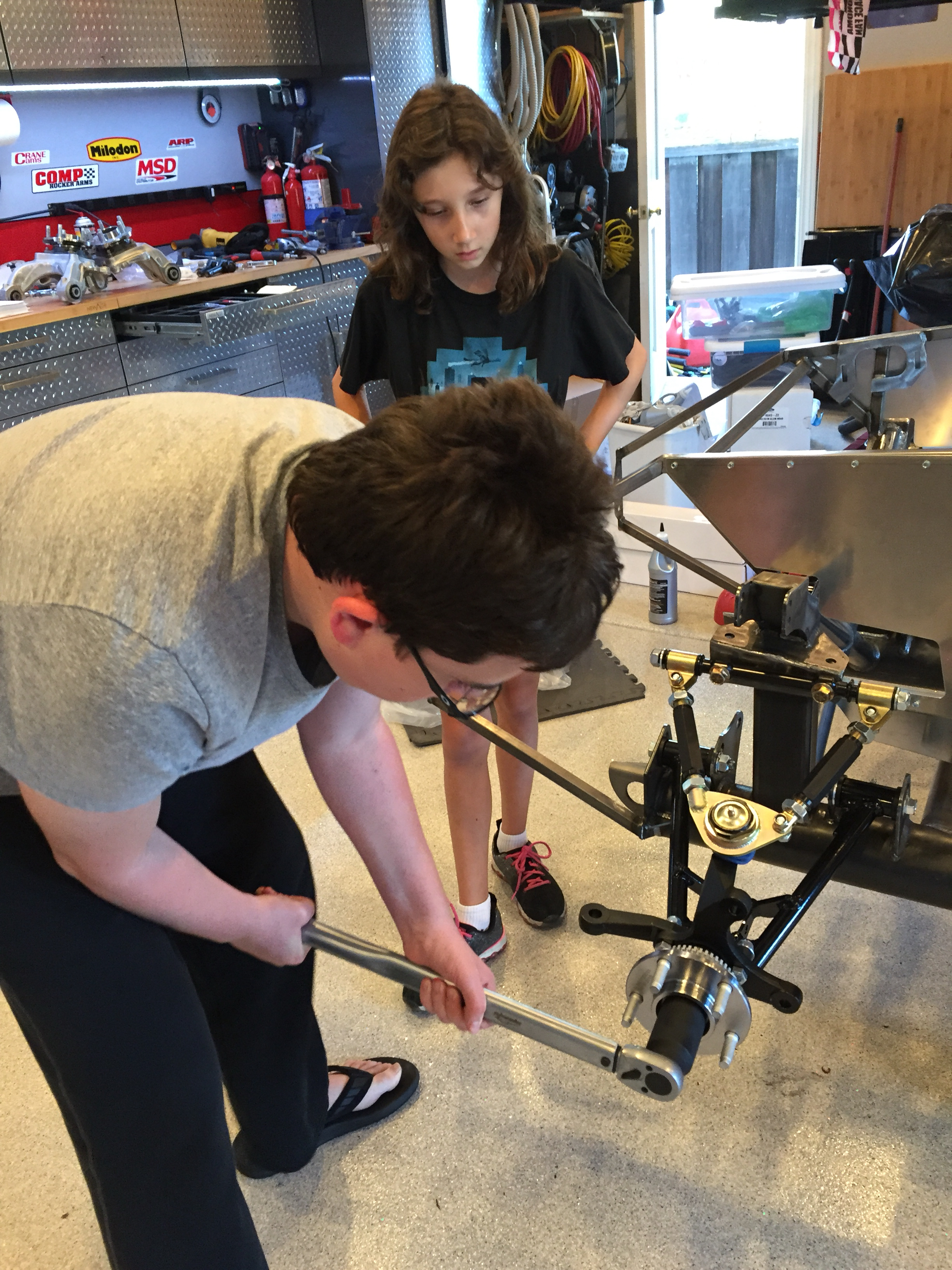
Now that Madeline’s an expert, she can supervise Matthew as he tightens the other axle nut. After the kids took them as far as they could, I torqued them to spec.

After wrapping up the front hubs, we moved on to installing the differential. Jenn’s tapping the bushings into the front mounting holes.

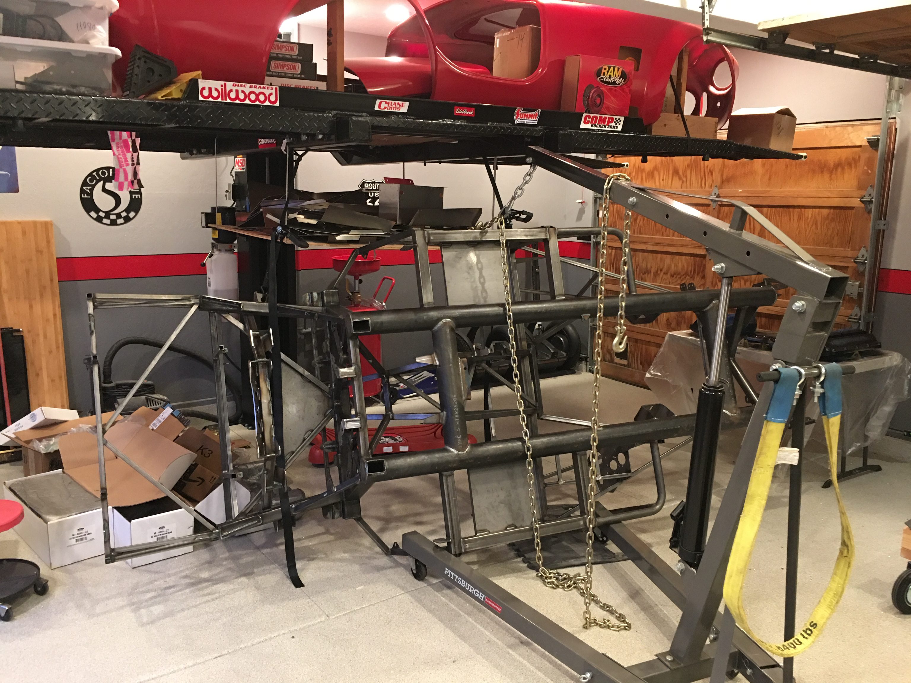
Getting the diff in place wasn’t too painful. We stood it on end and used the floor jack to lift it most of the way into position. I then pivoted the diff horizontal while Jenn started the rear bolts.

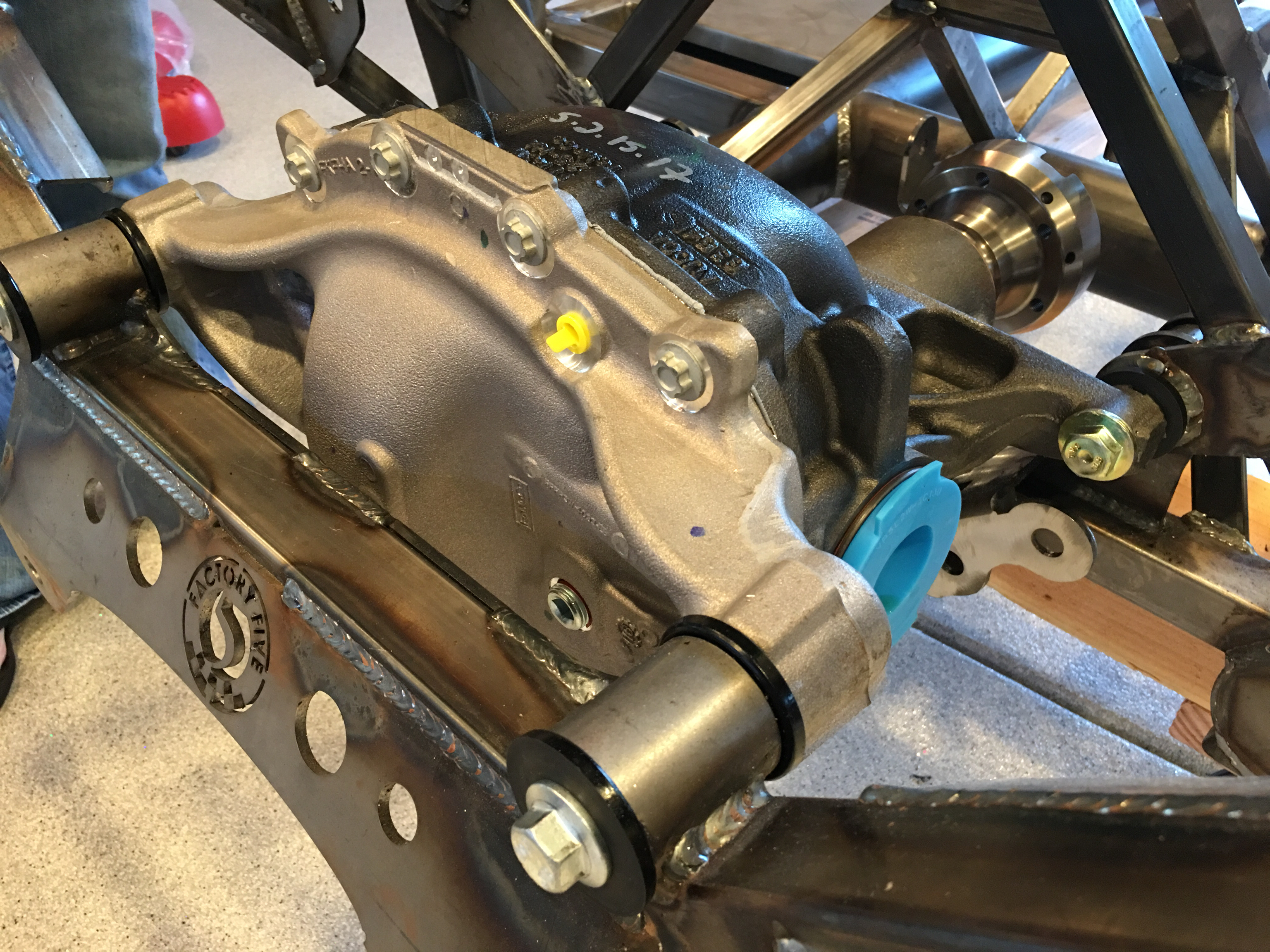
After installing the front bolts, Jenn torqued everything to spec.

We assembled the toe arms and bolted them in place.

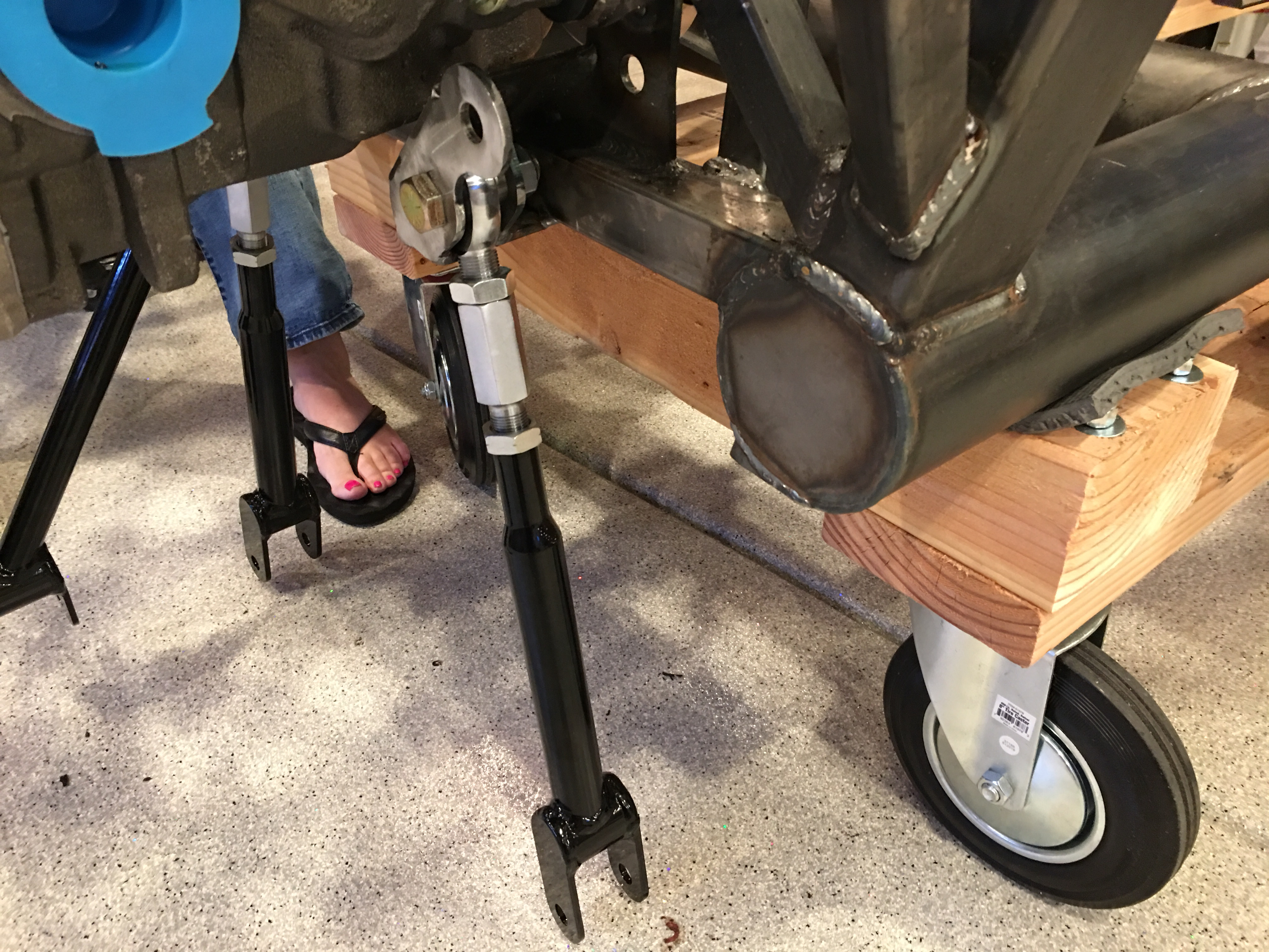
We then bolted in the lower control arms and torqued them to spec.

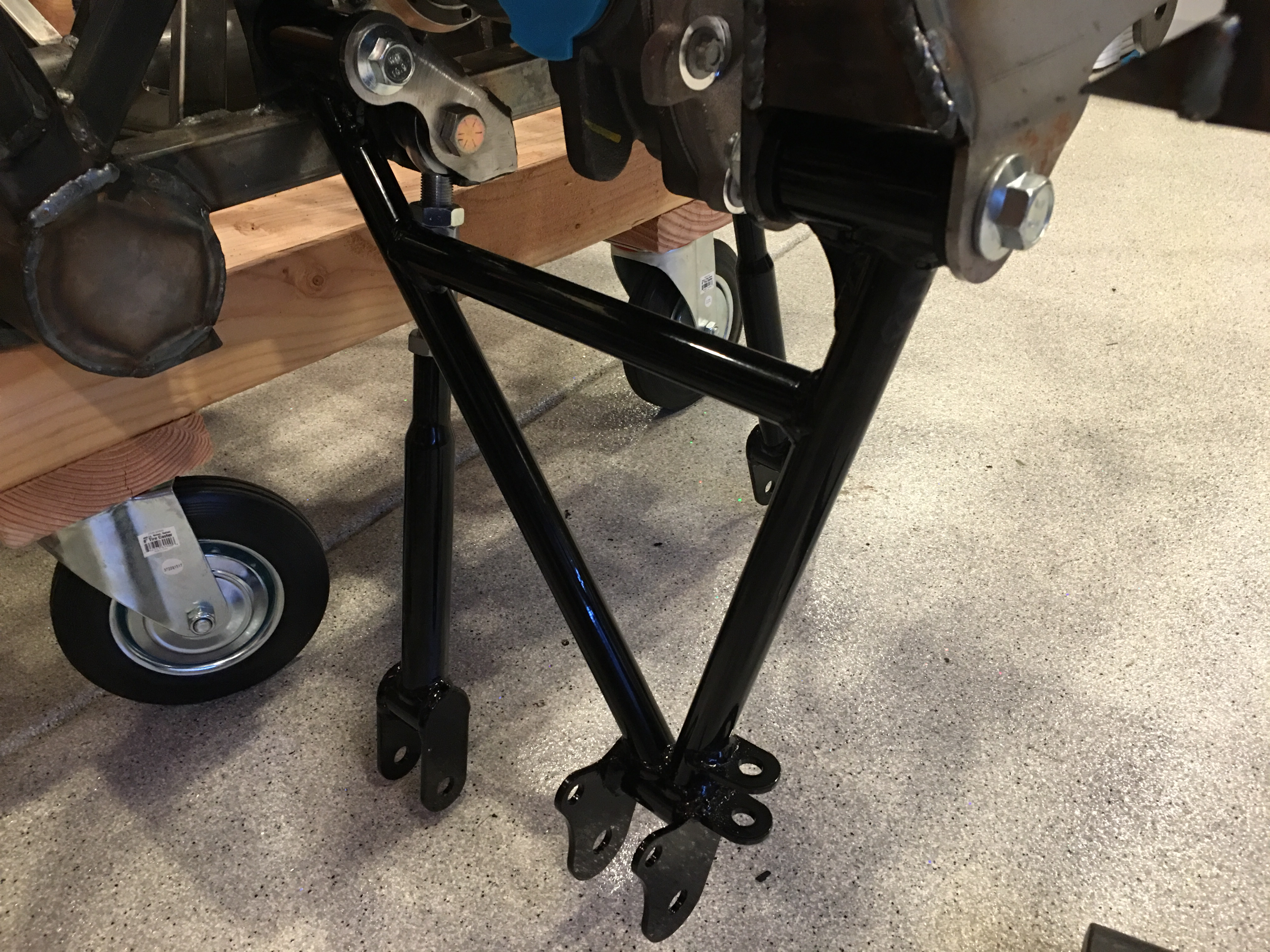
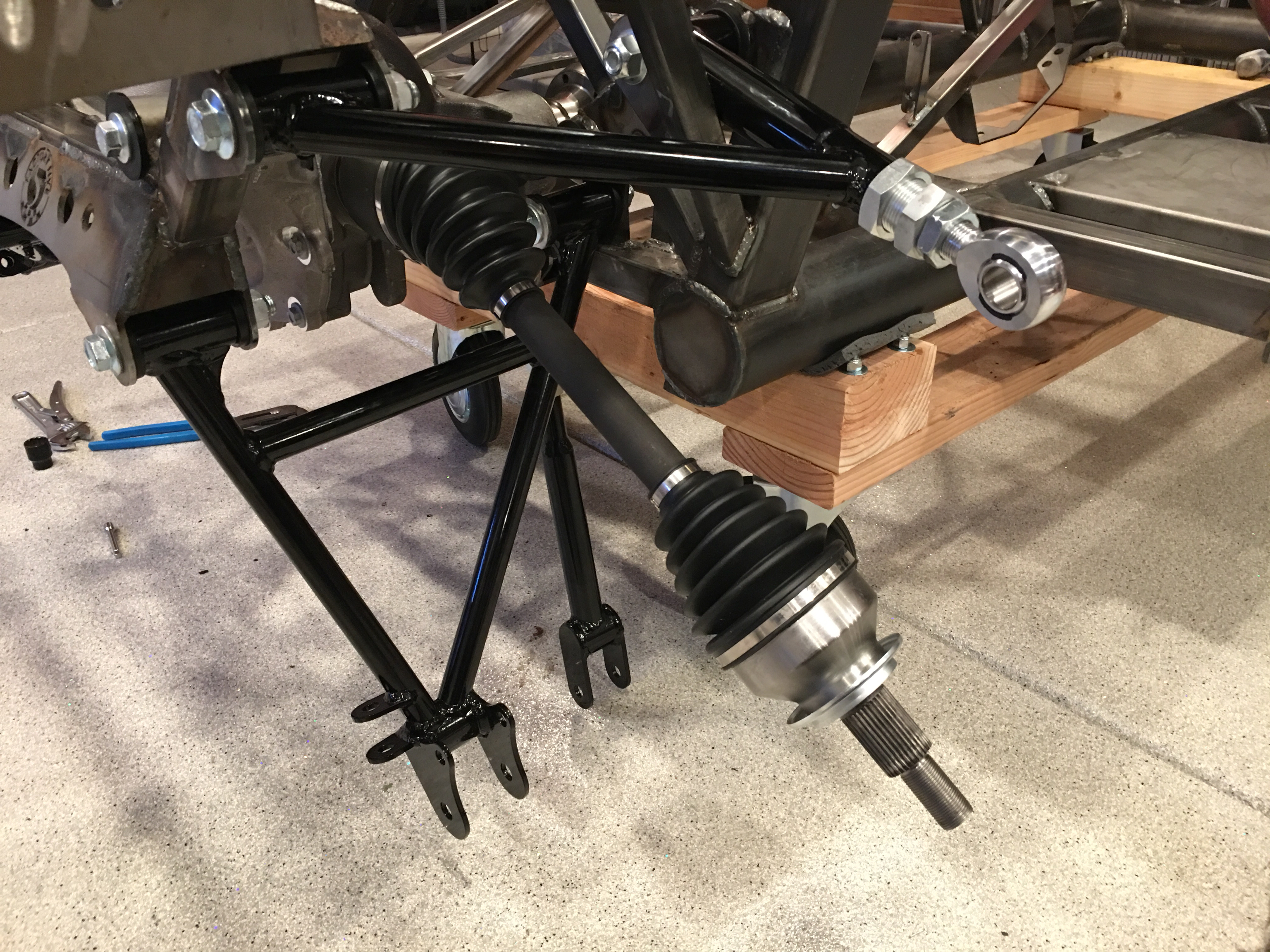
After inserting the half shafts, we bolted in the upper control arms.

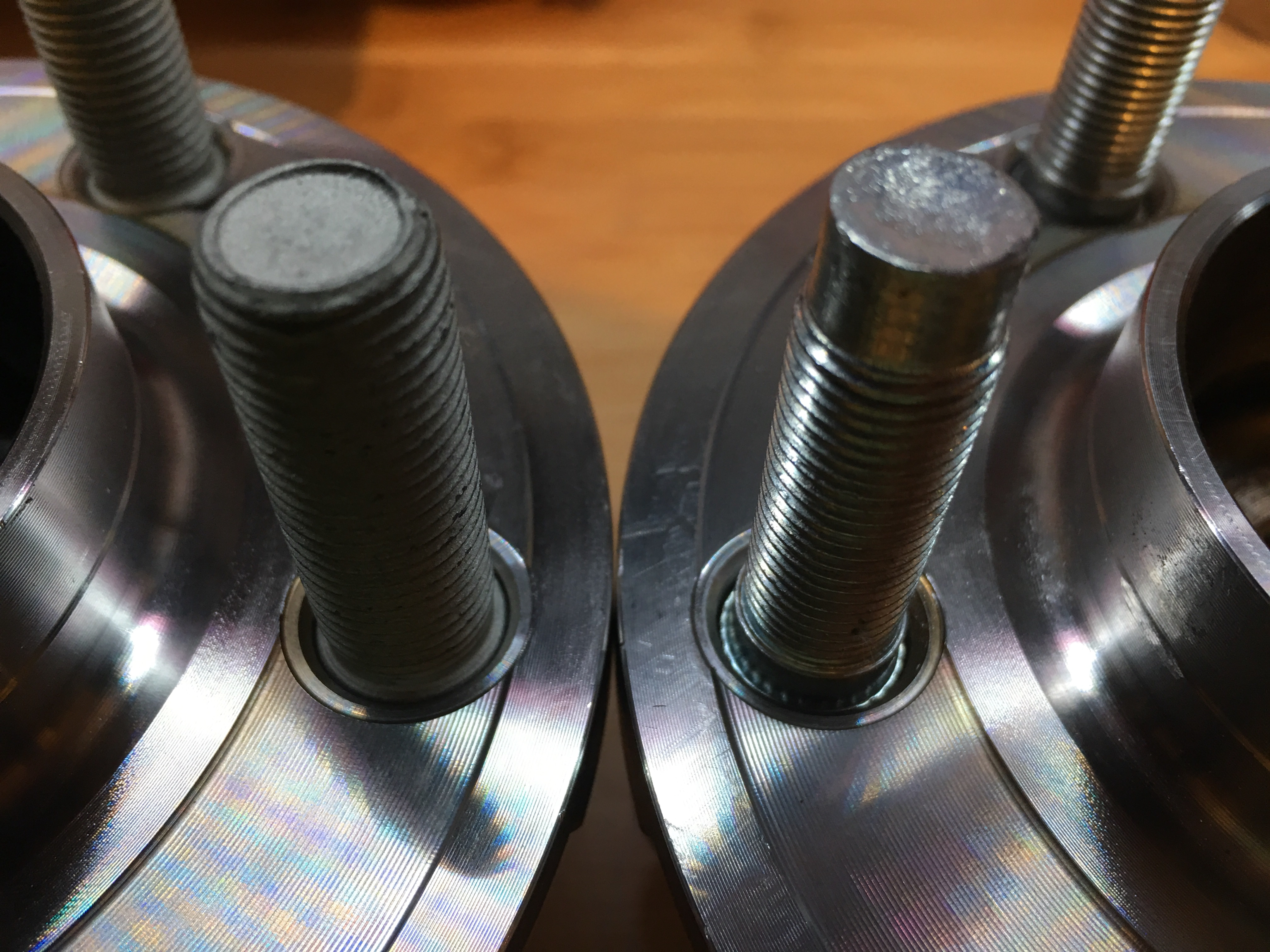
We slipped the rear hubs over the end of the axle and used the axle nut to pull the hub part way onto the shaft. We then aligned the three mounting ears with the various control arms and bolted it in place. We then torqued the axle nut and mounting bolts to spec.

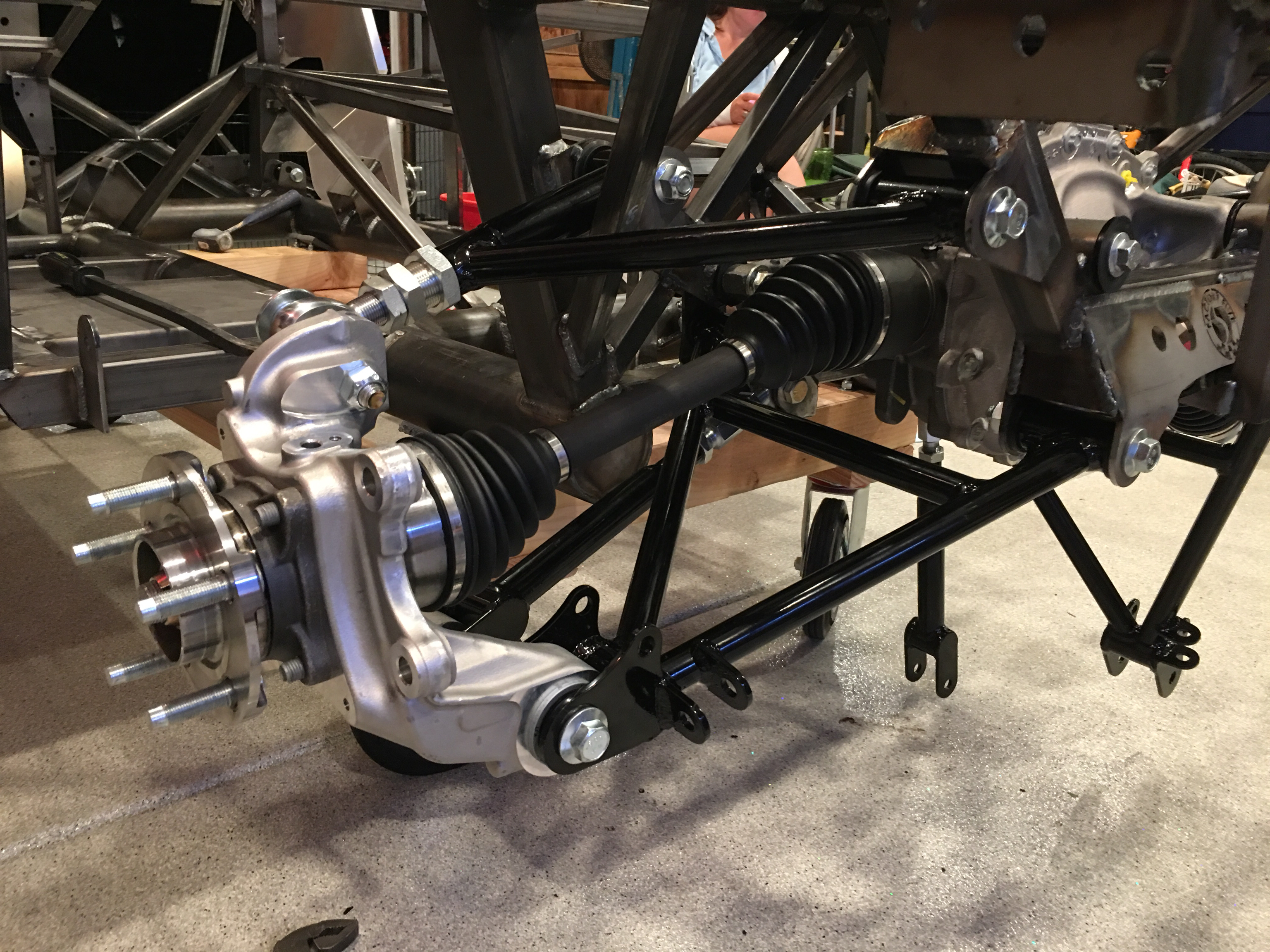
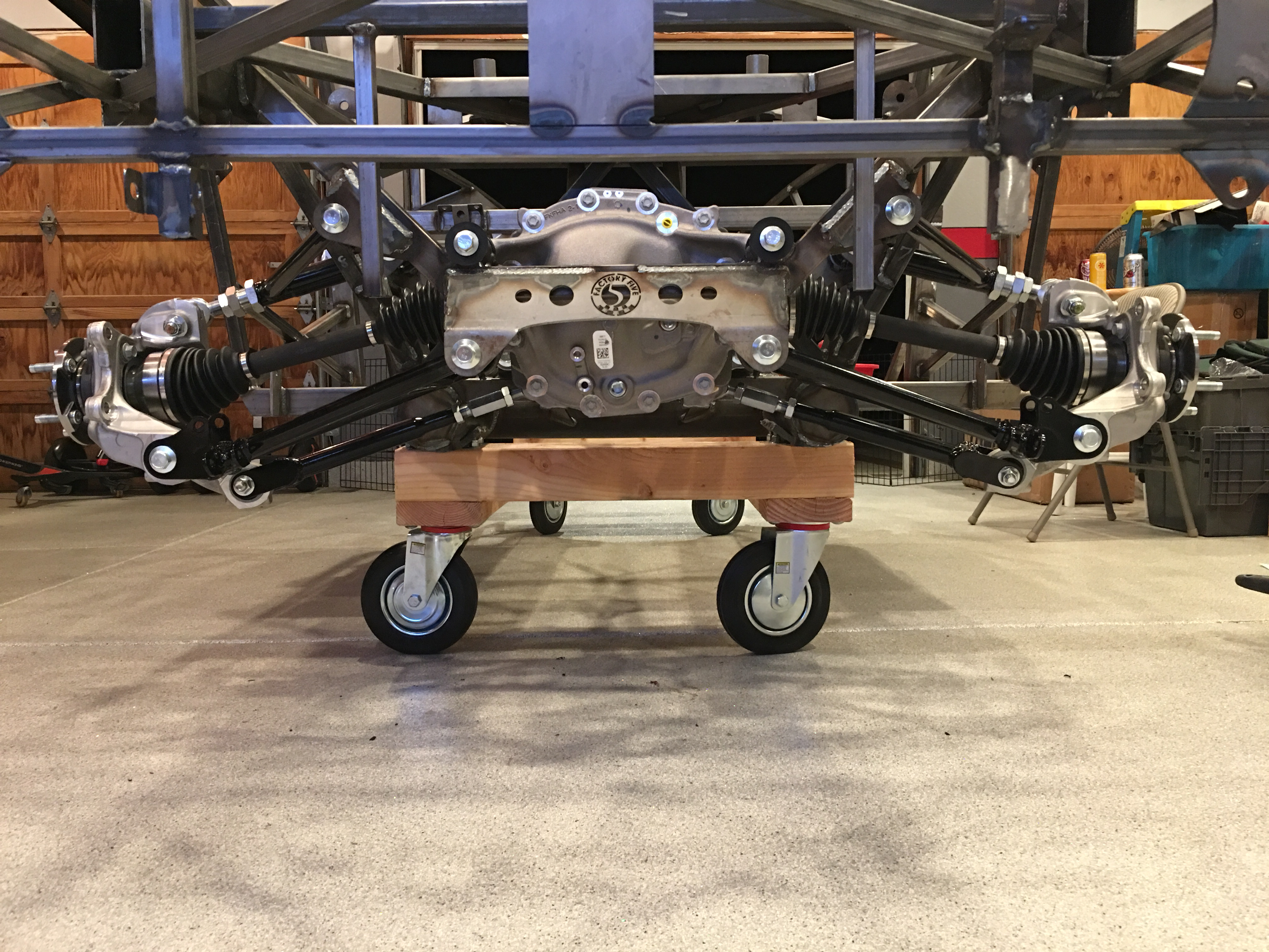
The entire IRS it installed; it looks pretty damn sweet!

Installed New Studs in Rear Hubs

The hubs come from Ford with the wrong size studs. I’m not sure why they couldn’t just use these, but the kit comes with smaller 1/2-20 studs. You can see the difference between the old (on the left) and the new on the right.

Installing this was much more of a pain than the instructions would have you believe. It’s pretty trivial to knock out the old studs with a hand sledge, but the instructions have you use a lug nut and washer to draw the new stud into the hub. The problem is that it takes substantially more force to turn the lug nut than I could apply (and I’m quite a bit stronger than the average person). With an unlubricated lug nut, I could easily reach the recommended torque (100 ft-lb) long before bottoming out the stud. I ended us lubricating the studs with ARP Assembly Lubricant and using an impact wrench to draw the stud into place before applying a final torque with a torque wrench. It was a little bit of a pain to clean all of the lubricant out of the threads, but it was worth it given how easily it set the studs. I probably should have taken these down to the TechShop and used their large arbor press to press them in, but it’s done now.

Installed Tires and TPMS Sensors

I stopped by BR Racing this morning to get our tires mounted. They have a really nice touchless mounting system that grips the wheels through the lug nut holes.

I picked up a tire pressure monitoring system and had BR Racing install the sensors inside the wheels. The system has a really small display that should be fairly discrete on the dash.

Painted Engine and Prepped Chassis

I still need to do a little more grinding on the bottom of the chassis to clean up some of the weld splatter and sharp edges. I’m also planning on welding steel floorboards onto the bottom of the chassis to better protect from road debris. I wanted to get a better look at the bottom to see if I needed one or two pieces of steel. The bottom of the round tube is essentially flush with the bottom of the square tubes, so it looks like I can use a single piece.

I finished taping up the engine block, heads and timing chain cover and cleaned them thoroughly before painting them with three coats of Eastwood’s high-temperature ceramic engine paint in gloss black. I haven’t pulled the tape yet since I want the paint to be fully cured before touching it. Touching the overspray on the tape showed that it will be easy to leave fingerprints in the paint until it’s cured.

All of the surfaces on the heads and blocks that were painted were a fairly rough case surface, so it doesn’t result in a truly glossy surface, but I think it looks really nice.

The timing chain cover is a smooth casting, so it looks much more glossy.

While I taped up most of the front of the engine, there was a small oval part of the casting that had been sanded smooth and engraved with the Ford Racing logo and block part number. I didn’t mask that off and painted right over it. I took some 320 and 400 grit sand paper and sanded off the paint on this oval.

This left the paint down in the engraved areas. It’s unfortunate that the “c” in Racing” wasn’t engraved properly, but I still really like the way this looks.

Received Wheels and Continued Masking Engine for Paint

We received our wheels from Factory Five today. These are the 17″x9″ front and 17″x10.5″ rear Halibrand replica wheels. I pulled them all out to make sure they look good, but didn’t get any pictures of them.

Afterward, I finished masking the block. Other than a final cleaning, this is ready for paint.

I thoroughly cleaned the timing chain cover and started masking it for paint. The process I’ve been using is to use tape around the perimeter of each section with regular masking tape since it sticks better than the blue tape, then using a razor blade to slice to the exact edge. Larger areas are covered with blue tape or aluminum foil. This is pretty time consuming, but it should produce a nice finished product.

Started Masking Engine

During the virtual engine build, I marked the head gaskets where they hung out beyond the block or the head. Tonight I finished trimming them to the lines I marked and then started getting the engine block ready for paint. I got about 2/3 of the block taped up before running out of steam; there are a ton of spots to mask on these blocks.

Virtual Engine Build

My dad stopped by this morning and we did what we’re calling a “virtual engine build”. We test fit most of the components and verified we had all of the right parts and the right bolts to fasten them on. We also confirmed we had the right sealants, tools and torque settings.

We got started on the bottom end, fitting the oil pump, oil pickup and oil pump driveshaft. We then fit the oil pan and confirmed we had the right clearance between the pickup and the bottom of the pan by taping over the oil pickup and using a small piece of modeling clay. The only issue we ran into was that one of the nuts in the ARP oil stud kit had the wrong thread pitch. I’ll have to call them on Monday and get a replacement.

We then fit the timing chain cover and water pump. Although the ARP bolt kit I ordered from Summit Racing said in contained both timing chain cover bolts and water pump bolts, there were a bunch of missing 5/16″x18 bolts: 2@1.5″, 2@2″, 1@2.75″, 1@3.5″ and 1@5″. ARP said to contact them if the bolt set didn’t contain everything we needed, so hopefully they’ll send these or sell them individually to us. We also confirmed there will be clearance between the harmonic balancer and the water pump. The only potential issue we may have is that I purchased a timing pointer that mounts at the 2 o’clock position which is right under the water pump inlet. I *think* we’ll still be able to read the timing marks after the harmonic balancer is installed, but I may have to purchase one that mounts at the 11 o’clock position.

Finally, we mounted the heads and intake manifold. I’m trying to use all ARP 12pt stainless hardware for this engine build, but unfortunately, ARP doesn’t make stainless head bolts or studs for the 351W. They do for other engines, but apparently there hasn’t been much demand for them with this engine. They do may black oxide bolts and studs, but mostly with hex heads. The only option for 12pt hardware is studs. Given how far back the engine sits in the Cobra, the only disadvantage to studs is that I won’t be able to remove the heads with the engine installed in the car since the heads have to slide straight out until they can clear the studs. I really don’t think that will be an issue. I really like the studs though since they allow full thread engagement in the block and the thread bearings surface will the fine-pitch threads on the studs instead of course-pitch threads in the block.

One issue we ran into a couple of weeks ago was the rocker alignment on the valve stem. With the stock guide plates, the rockers were not perfectly aligned with the ends of the valve stems but were hanging somewhat off to one side. I purchased a set of AFR adjustable guide plates which gave me the ability to independently adjust the alignment of the intake and exhaust rockers. You can see the difference between them in the picture below. With these, I was able to adjust the rockers to be perfectly in the center of the valve stems.

Degreed Camshaft

I didn’t have too much time to work in the garage tonight, but I have been wanting to degree the cam before any more work happens on the engine. I started by attaching the degree wheel to the crankshaft and fashioning a pointer from a piece of safety wire attached to a bolt.

I fastened a dial caliper to the block so that I could determine TDC on the #1 cylinder. I found the dwell point at TDC at zeroed out the indicator. I then read the angle off of the degree wheel at 0.050″ before and after TDC.

After splitting the difference, I adjusted the degree wheel TDC.

I then installed a dial indicator in the lifter bore for the #1 intake valve.

I rotated the crankshaft until I got the lifter onto the base circle of the cam lobe then rotated the crankshaft further to determine the angle at 0.050″ of lift on the opening and closing side of lobe. I also determined the lobe centerline using a similar technique.

I then moved the indicator to the exhaust lifter bore and repeated the process.

I jotted down the values I read off of the dial indicator. The centerline was right on at 111º on the intake valve and 121º on the exhaust valve, so I know the cam is degreed correctly. I’m seeing a 6-7º greater duration at 0.050″ though. This could be due to a larger radius on the dial indicator ball end than the lifter roller, but I’m happy with the numbers.

Unlocked Transmission

Despite a warning on the side of the transmission shipping box, FedEx had it standing on its end when I picked it up. A note inside the box indicated that this can cause the transmission to lock up. Sure enough, I couldn’t rotate the input shaft; it would just rock back and forth but was clearly binding. Fortunately, there are instructions on their side about how to fix this.

I started by removing the center cover. This was stuck down with gasket maker and it was a pain to get off and clean up the excess sealant. Once the cover was off, it was obvious what the problem was. Despite the gearshift lever being in neutral, one of the shifter linkages was engaged. You can see the top linkage is closer to the forward (left) face of the cavity.

Popping this back freed up the transmission and the input shaft could now rotate freely.

I reapplied some gasket maker and reattached the cover. There is a good chance I’m going to take this off again anyway since we’re mostly likely going to move to the mid-shift position.

Measured for Pushrods

One of the goals for today was to measure for the pushrods so we have time to order them before assembling the engine in early July. After thoroughly cleaning the cam, we covered it with assembly lube and very gently slid it into the block. You can see the long bolt (wrapped in electrical tape) that we used to manipulate the cam.

After installing the cam thrust plate, we installed the timing set straight up. The cam has 5º of advance already ground into it, so we don’t need any further advance in the valve train. I didn’t get any pictures of the rest of the process, but we swapped a pair of valve springs for low-tension checking springs and used a Comp Cams length checker to determine the length. We determined that we need a 7.800″ pushrod and that results in a centered pattern on the valve stem tip that is about 0.050″ wide.