Coolant System Work

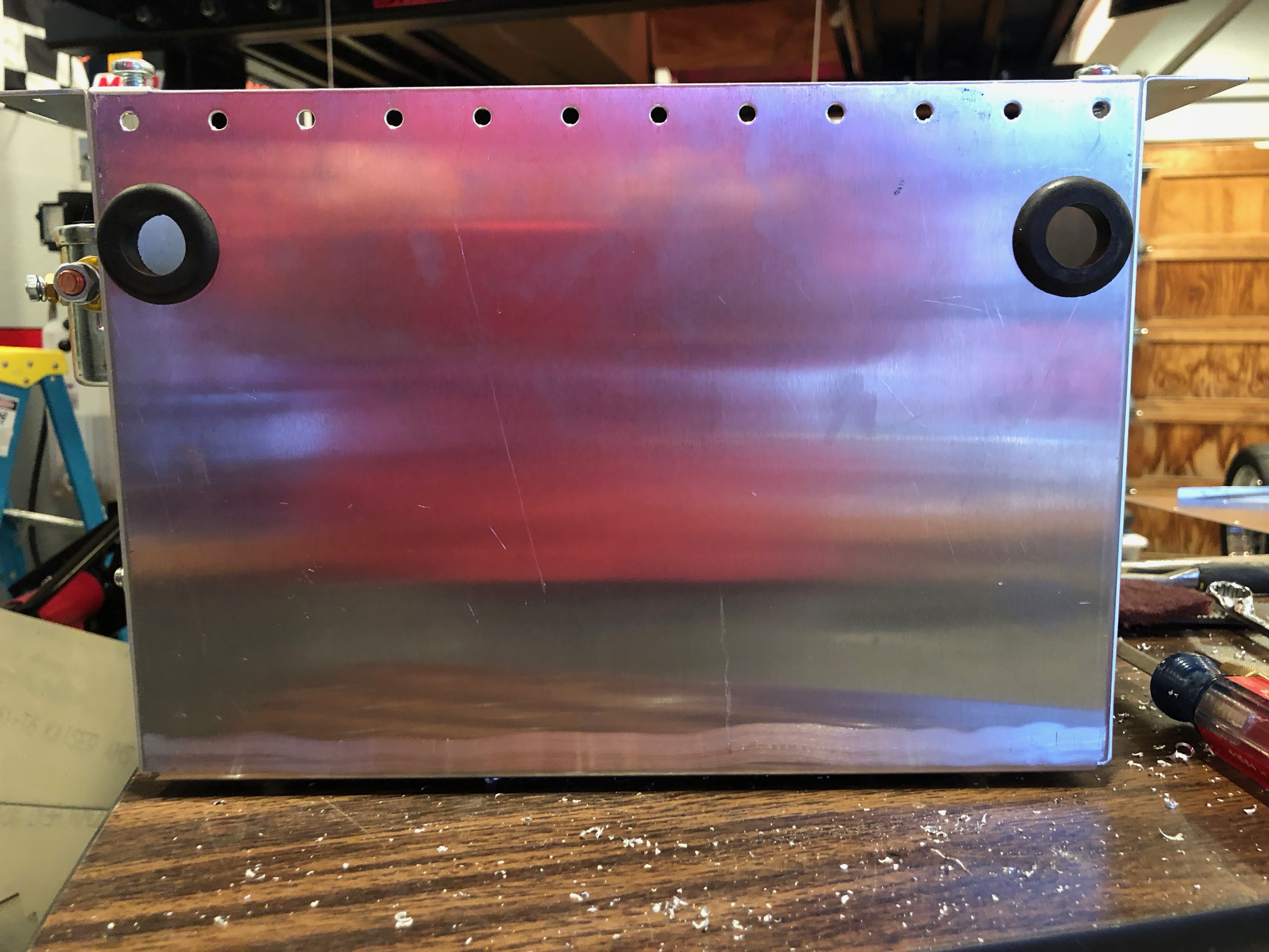
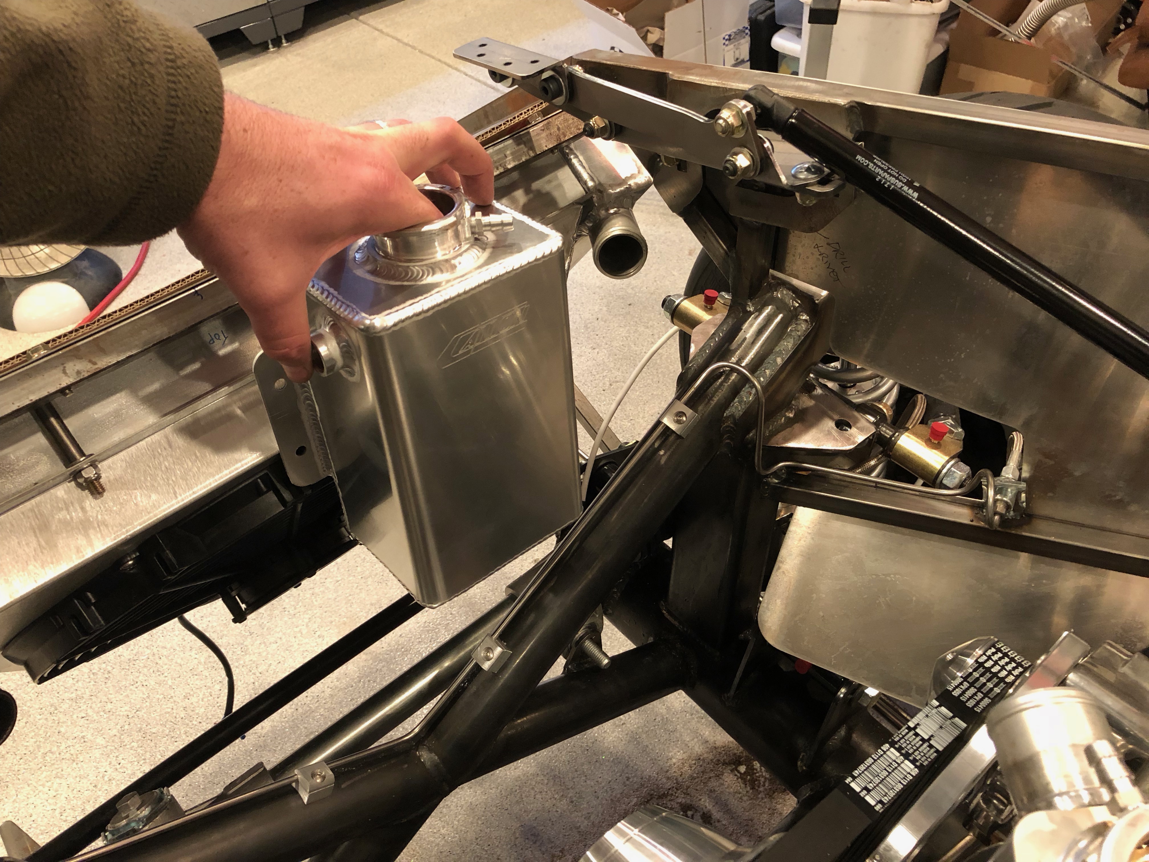
I received an order from Summit Racing with my new coolant overflow tank. Given the volume of coolant in the engine, the consensus on the forums is that the coolant reservoir tank that comes with the kit is too small. This tank from Canton Racing is over twice the volume at 2 qts. It’s also a beautiful piece of work.

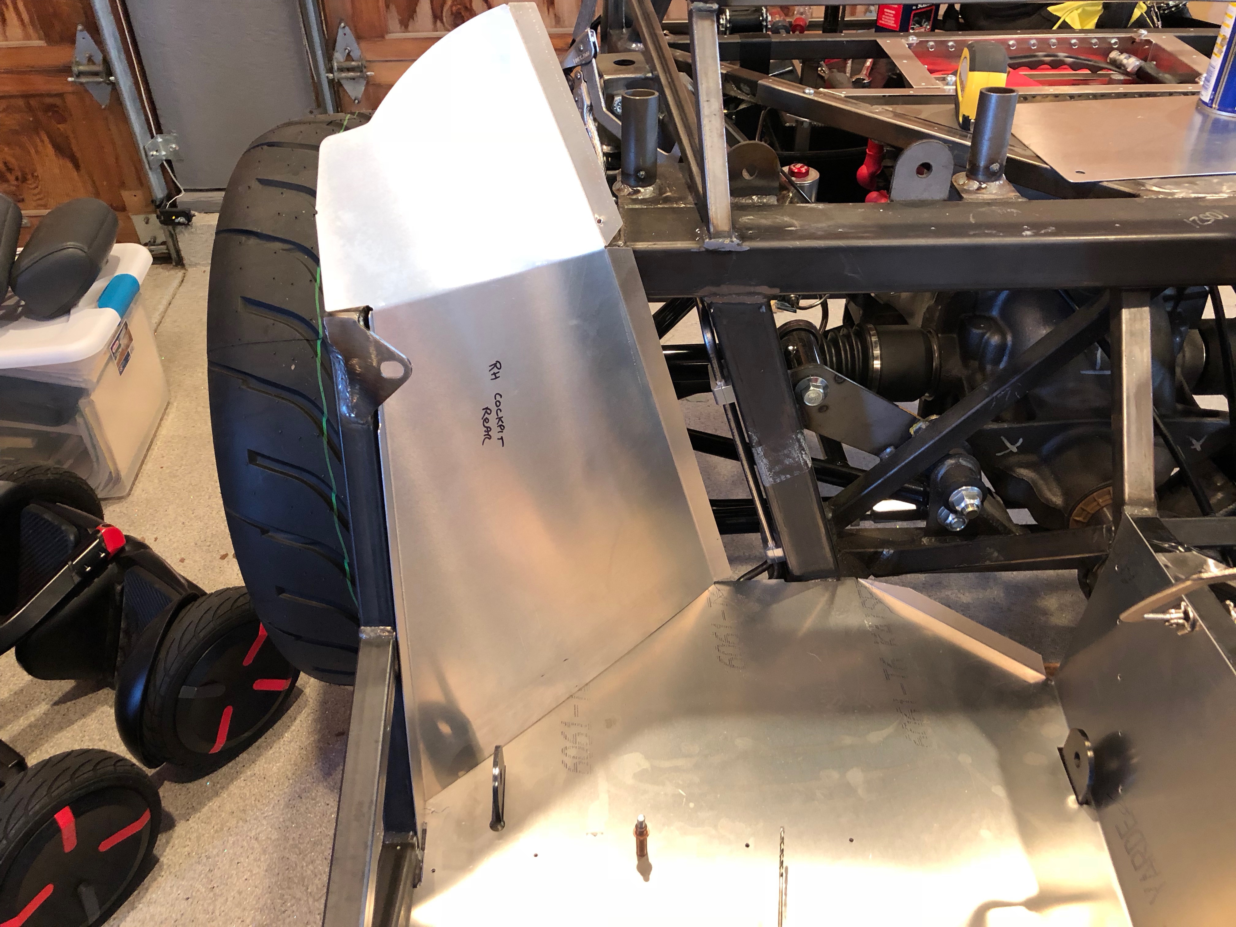
I have been thinking about mounting the reservoir inside the right F-panel. This should clear the upper radiator tube, but I’m concerned that it will interfere with the hood hinge and support strut.

To see whether that is true, I assembled the hood hinges.

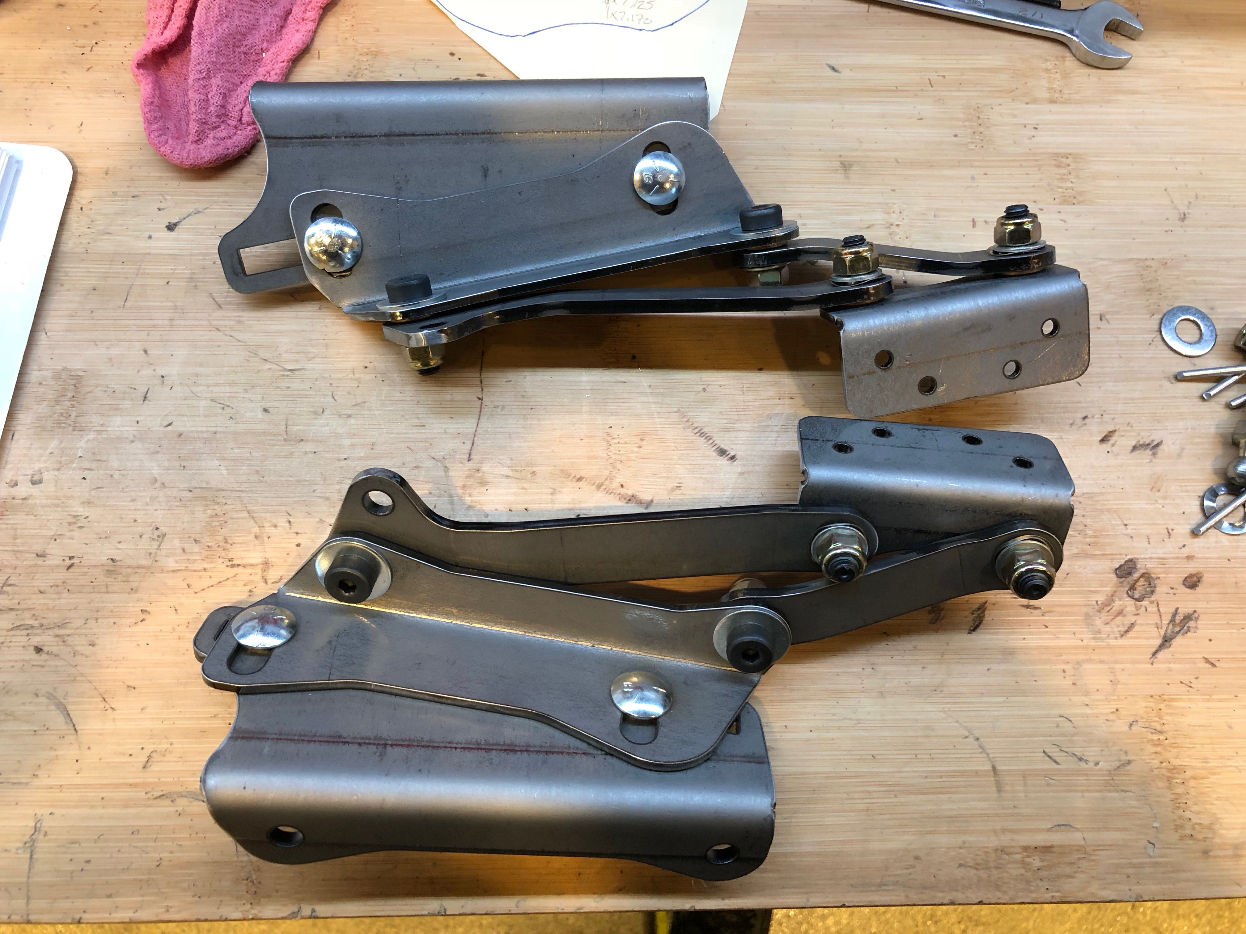
These attach to the brackets welded to the chassis just behind the upper radiator support.

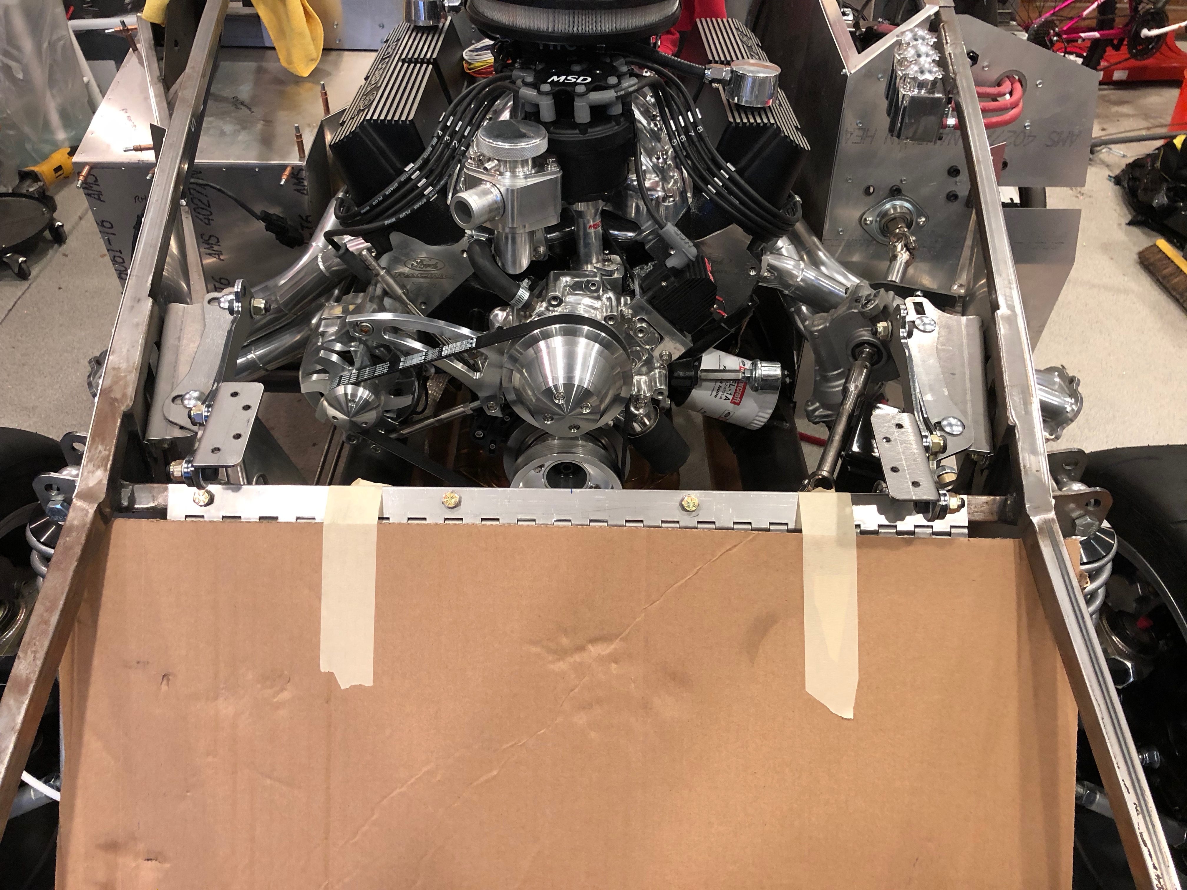
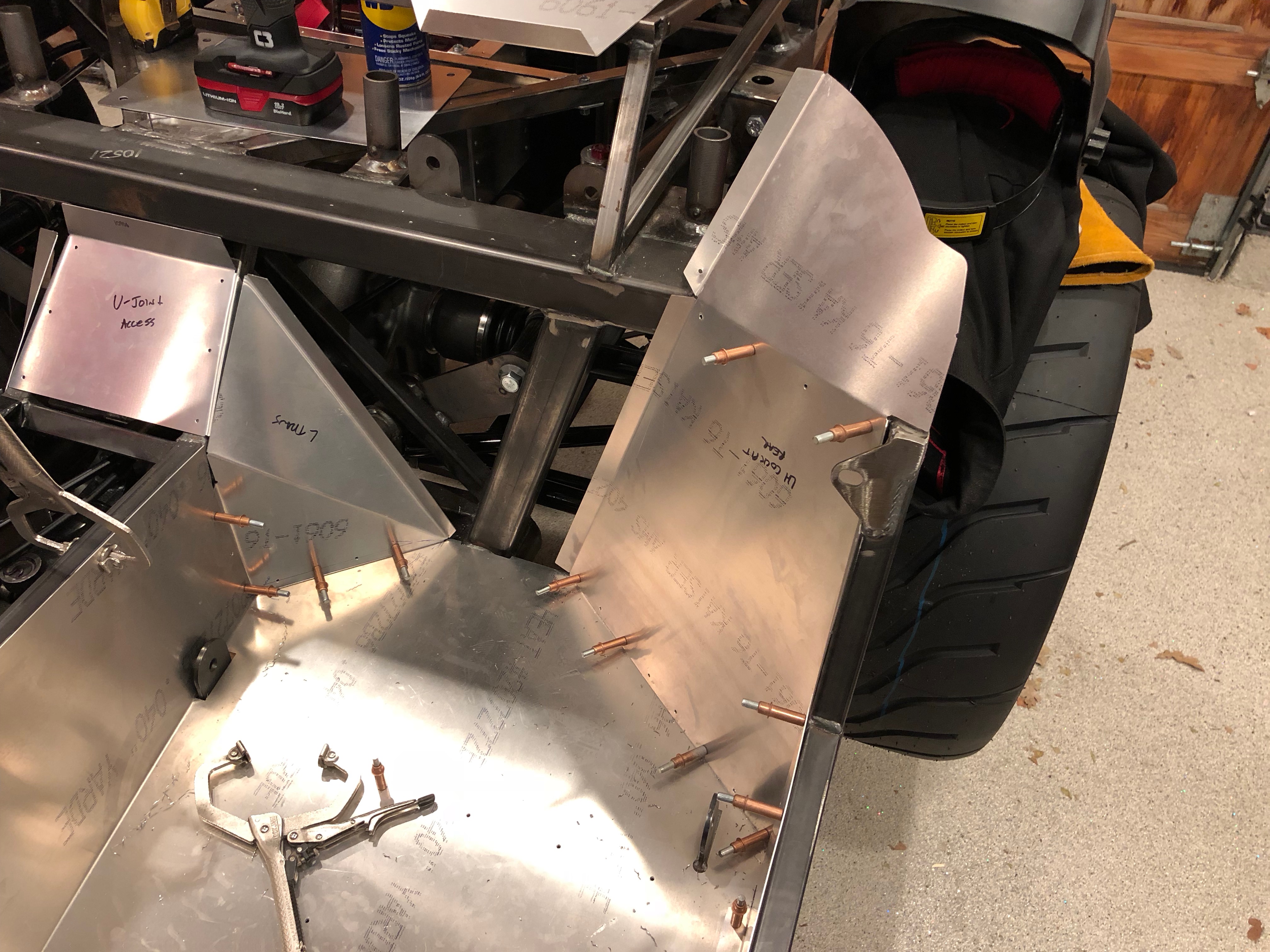
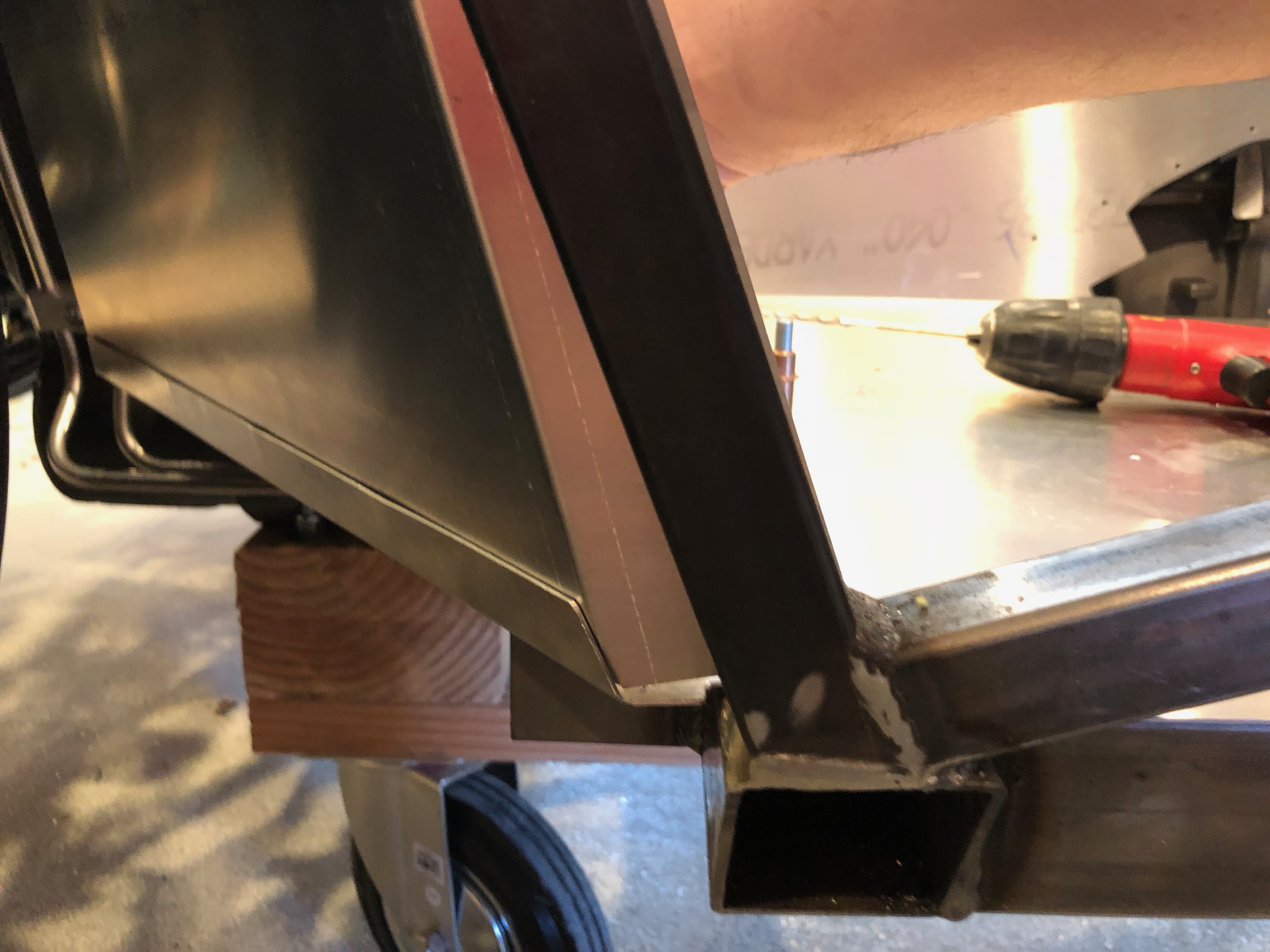
I installed one of the support struts to get a sense of how far back it extends (though it will obviously be compressed when the hood is down). From what I can tell, the aft end of the strut will be roughly level with the upper square tubing.

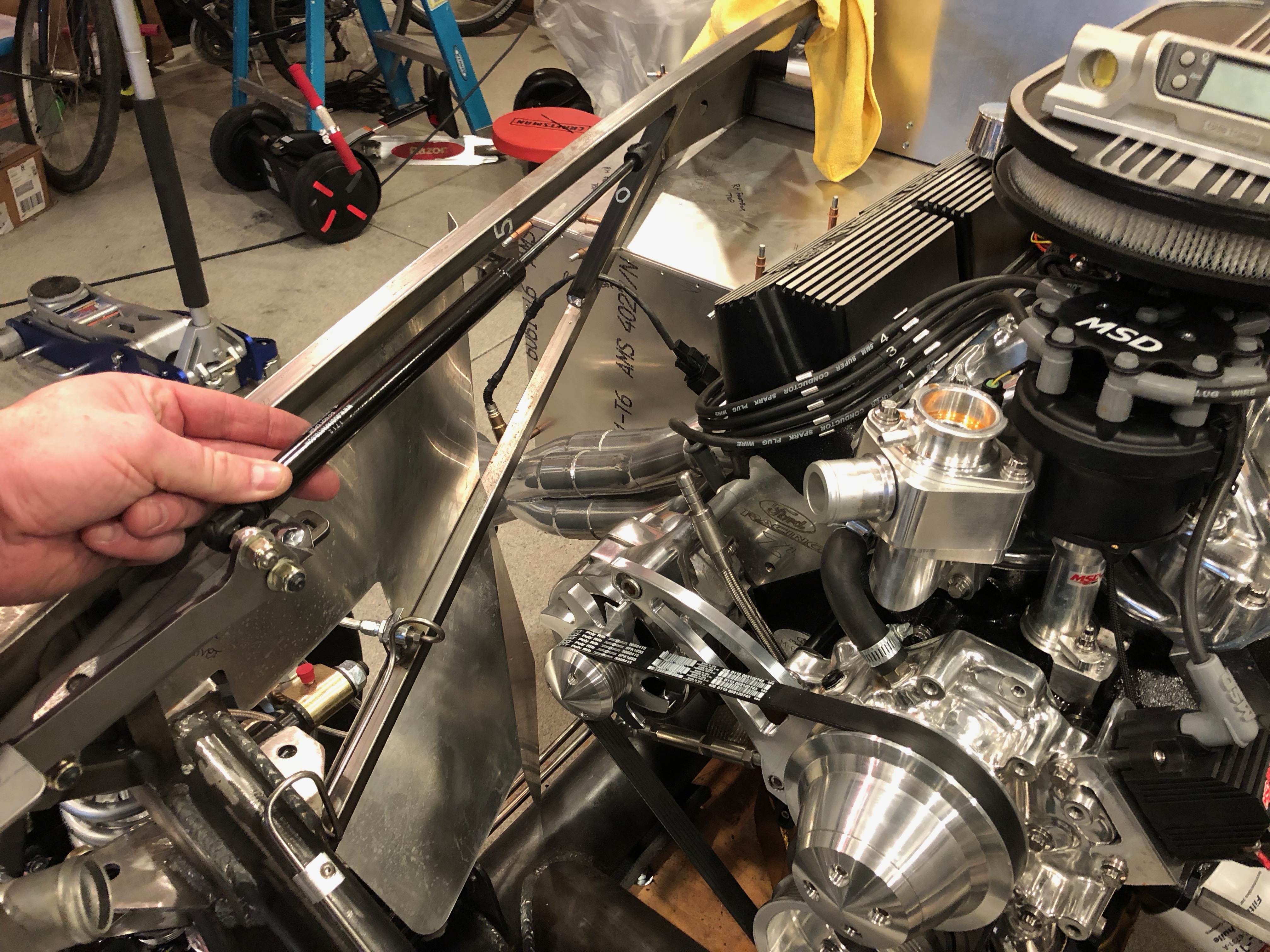
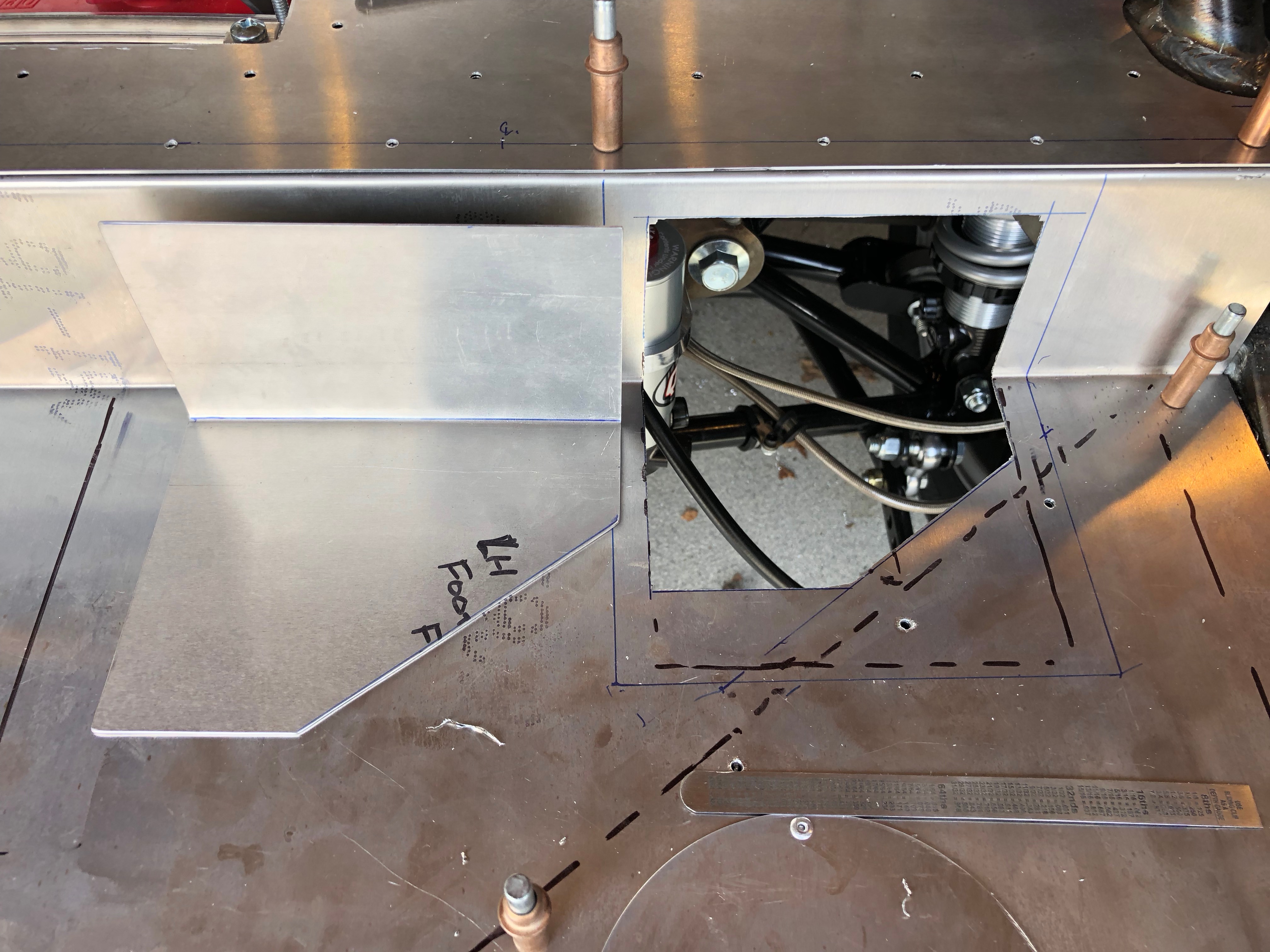
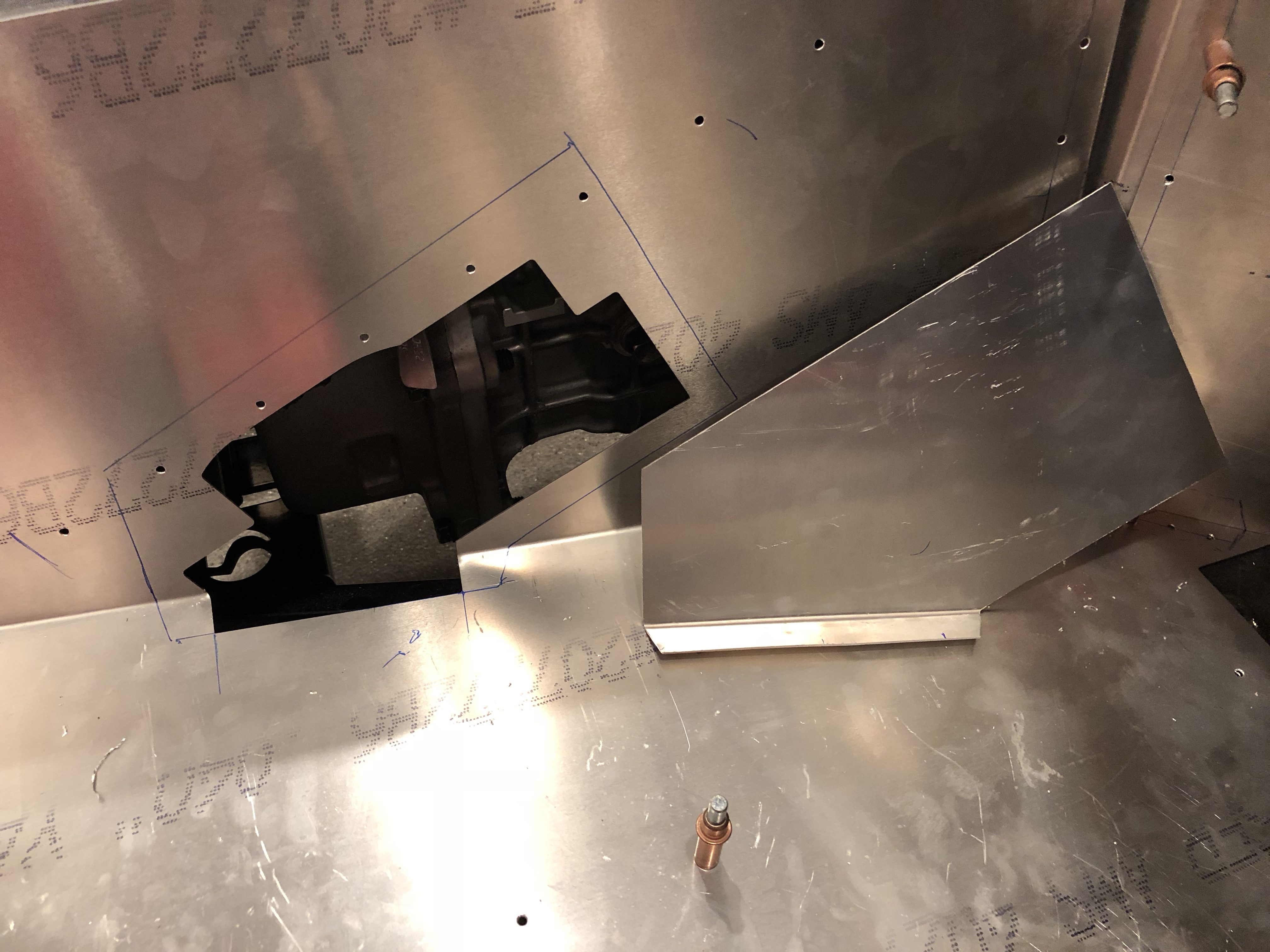
I might be able to install the reservoir inside the right F-panel underneath the support strut, but I’m concerned that the strut will push the reservoir too low. Another option is to mount it behind the radiator. I should be able to get it high enough here, but I’ll have to fabricate a rather complex mounting bracket.

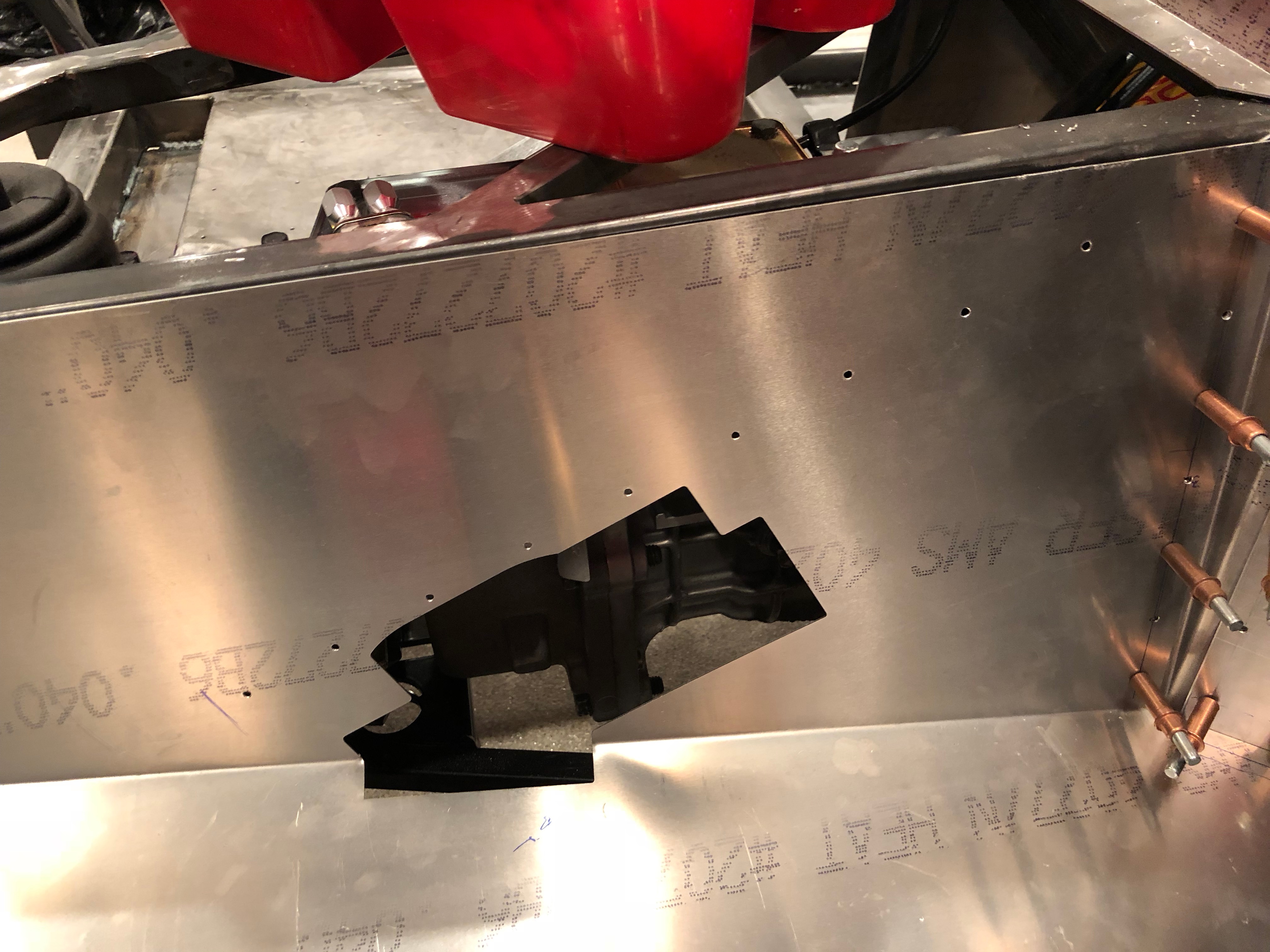
Now that I know that the upper radiator tube will clear the reservoir in either mounting position, I decided to go ahead and install it.

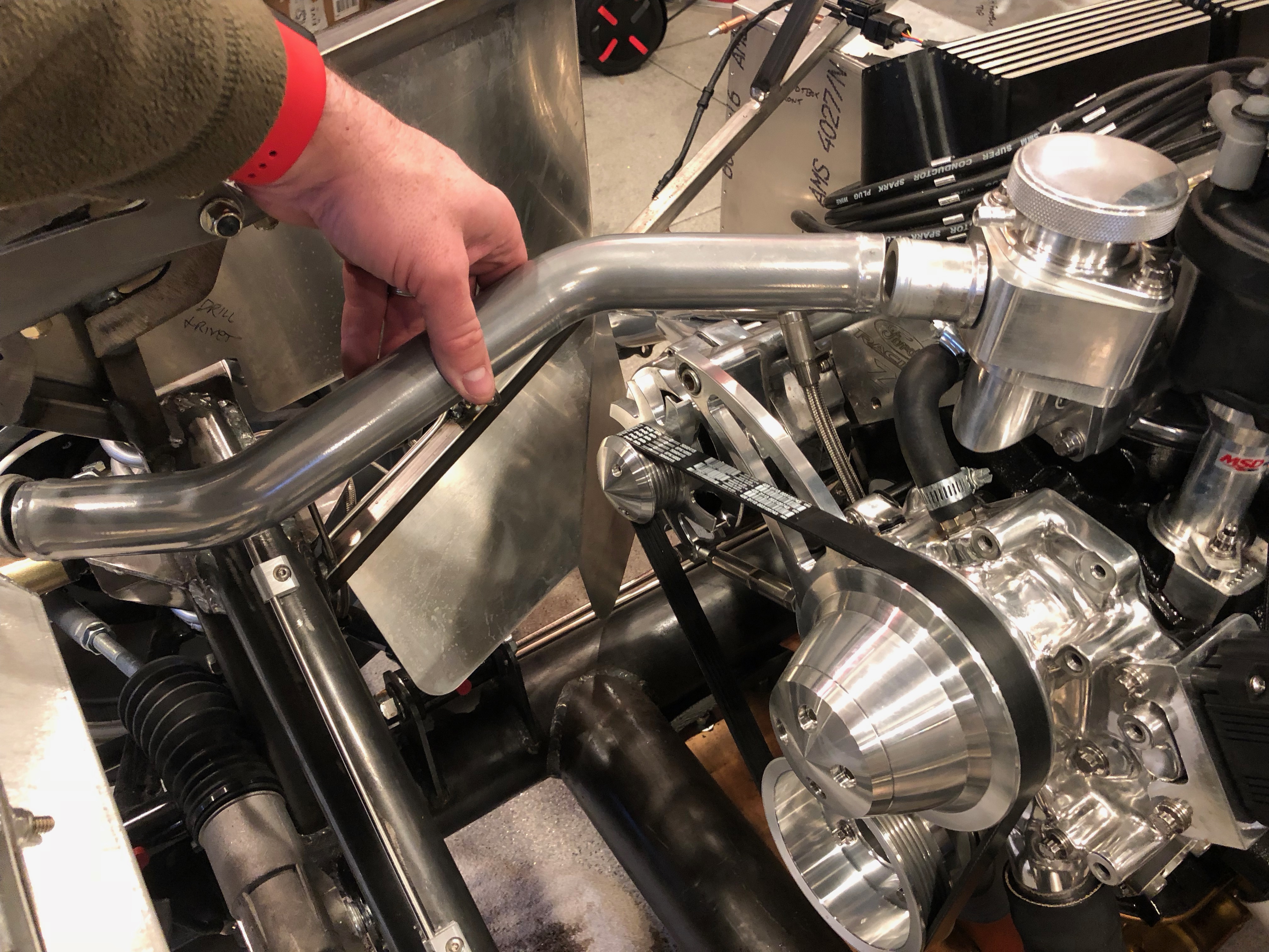
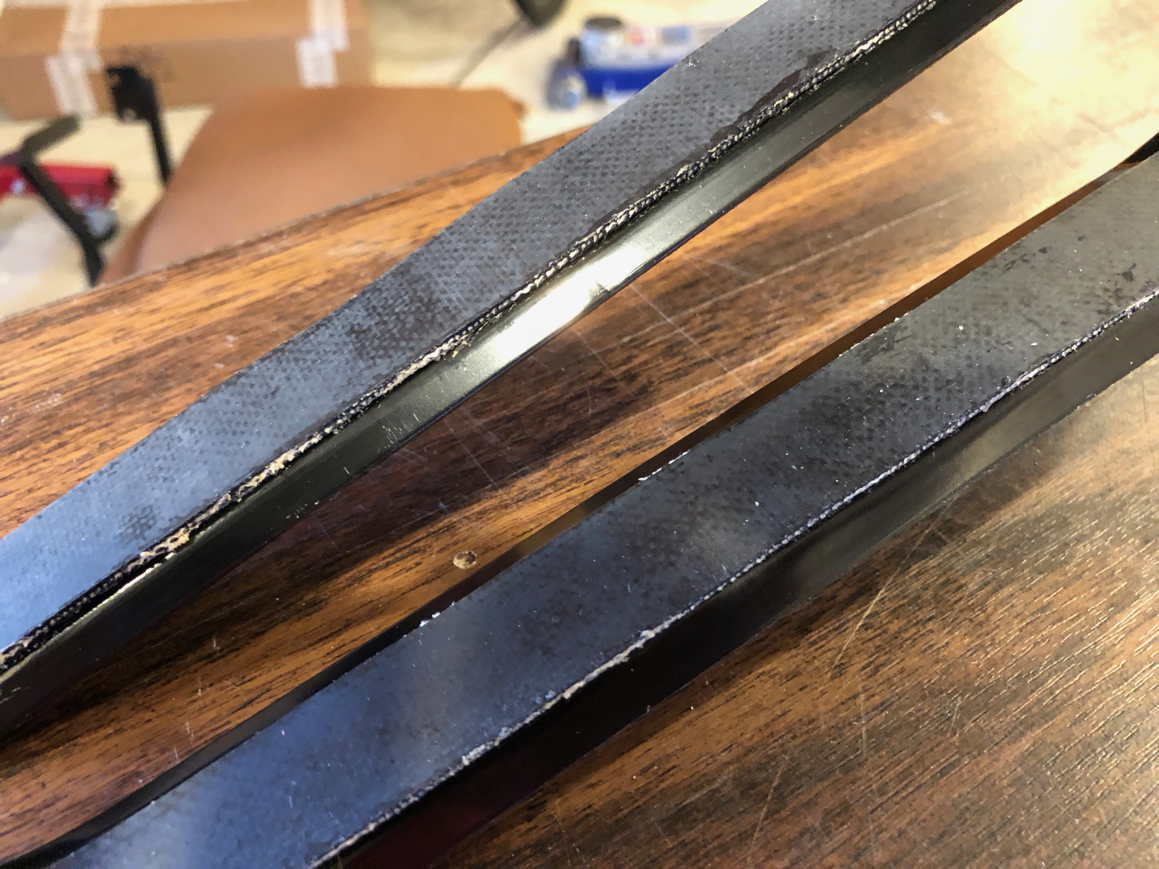
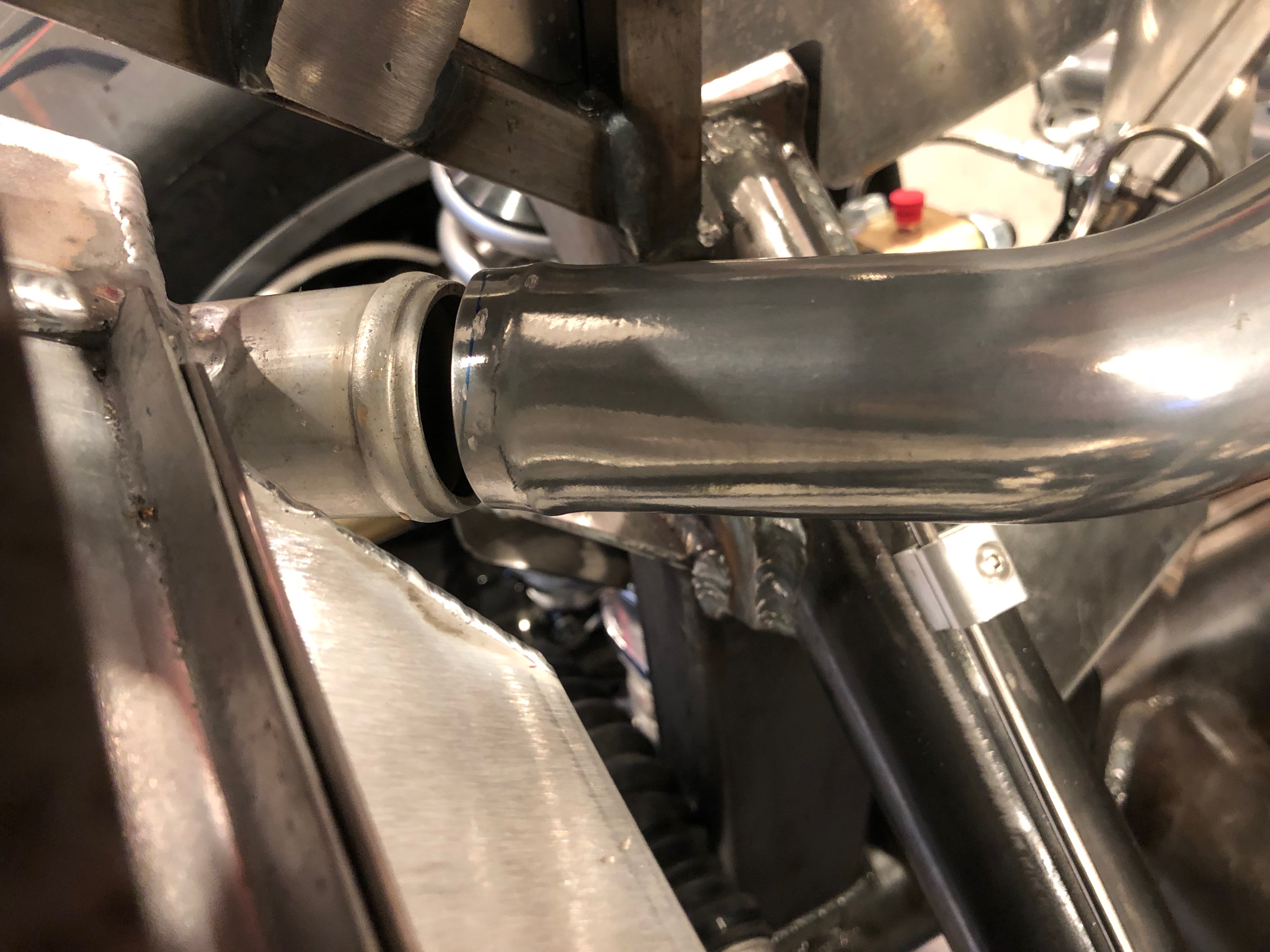
The tube was slightly too long to fit and there is a slight bend at each end. I cut a bevel to create a small gap at the aft end.

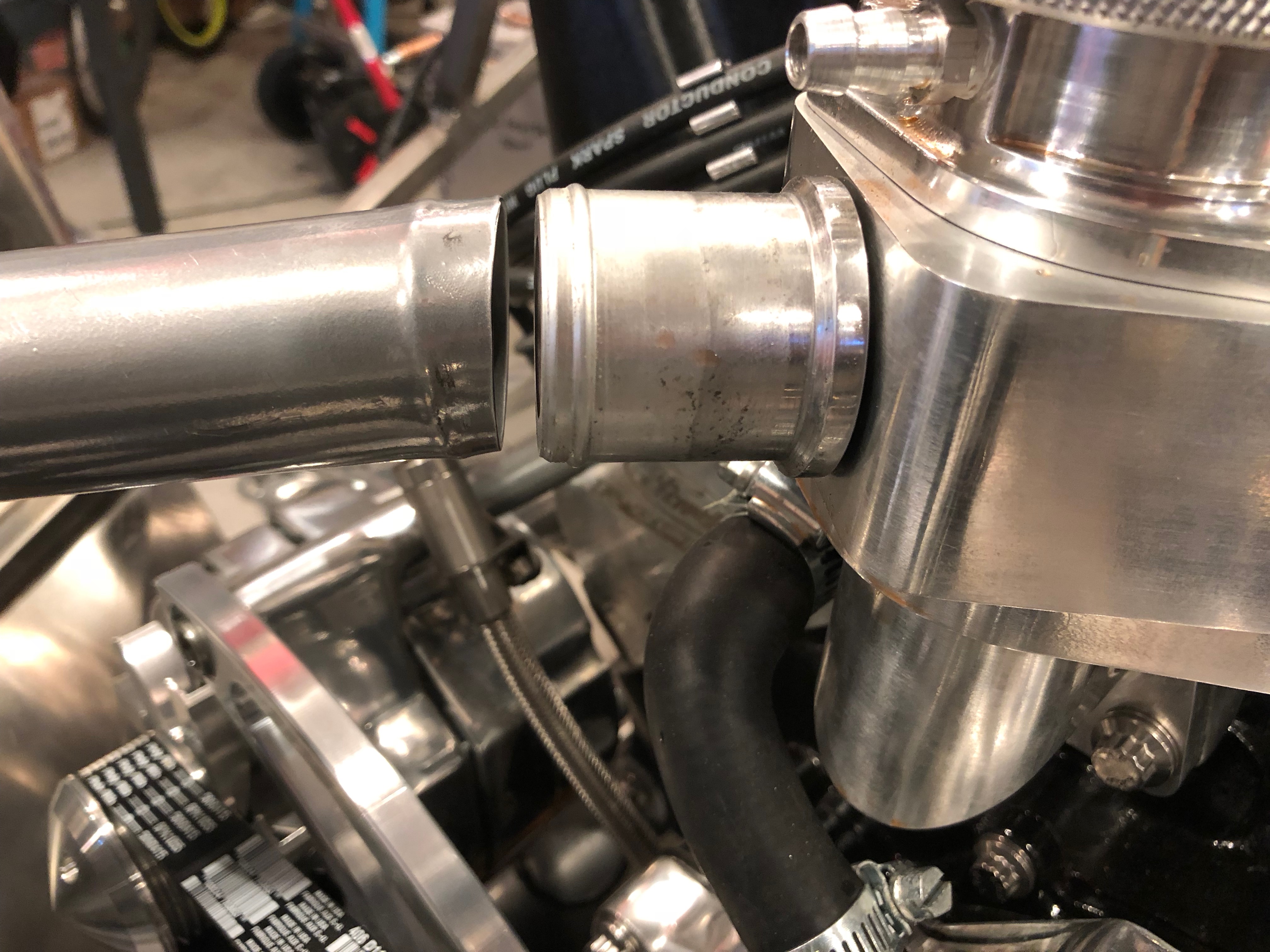
The forward end also needed a slight bevel to create the necessary gap between the tubing and the radiator.

Finally, I installed the upper tube in place and secured the clamps.

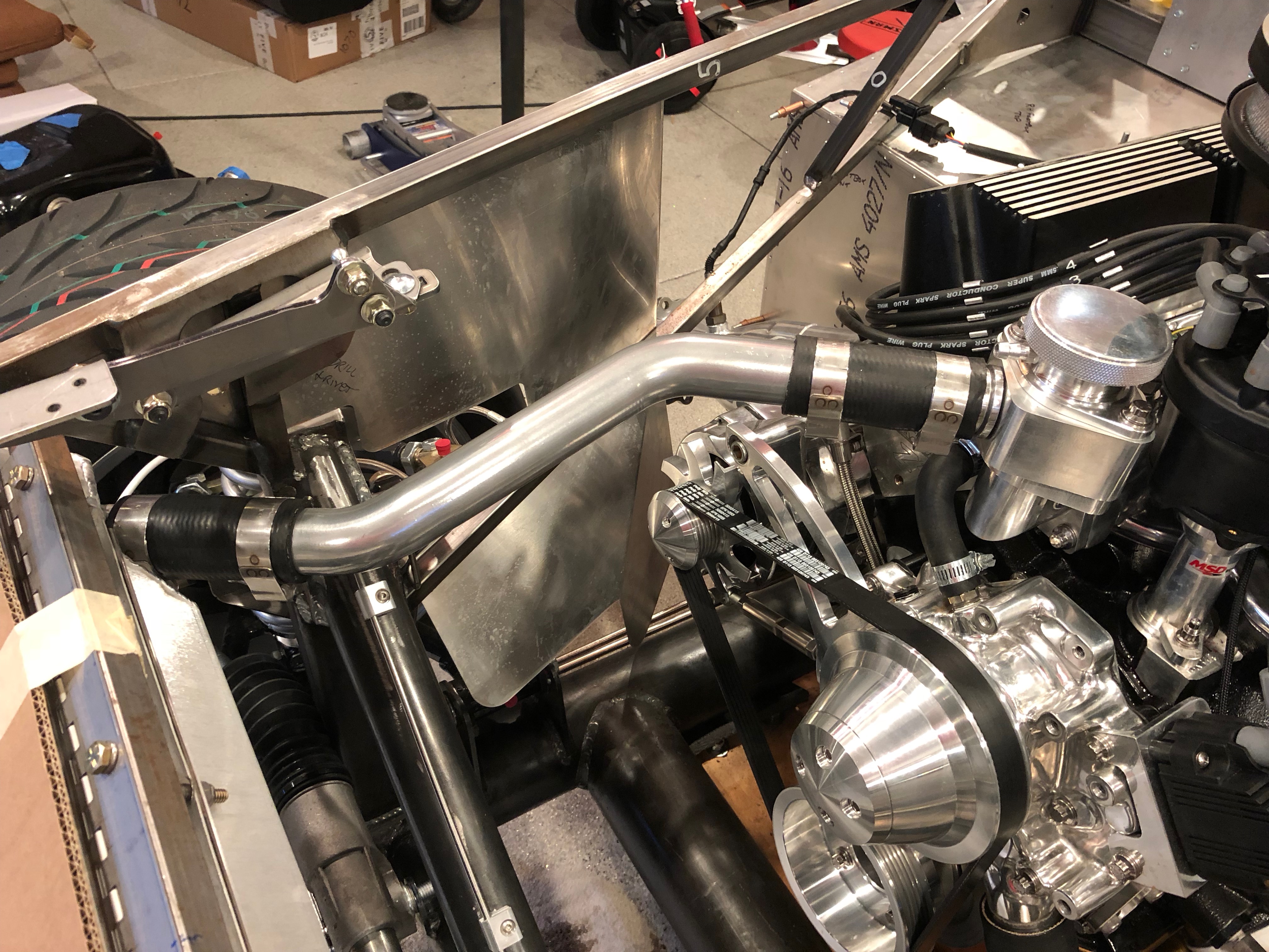
I used some T-bolt clamps to secure the rubber connecting hoses in place. These are so much better than the worm clamps that I was using.

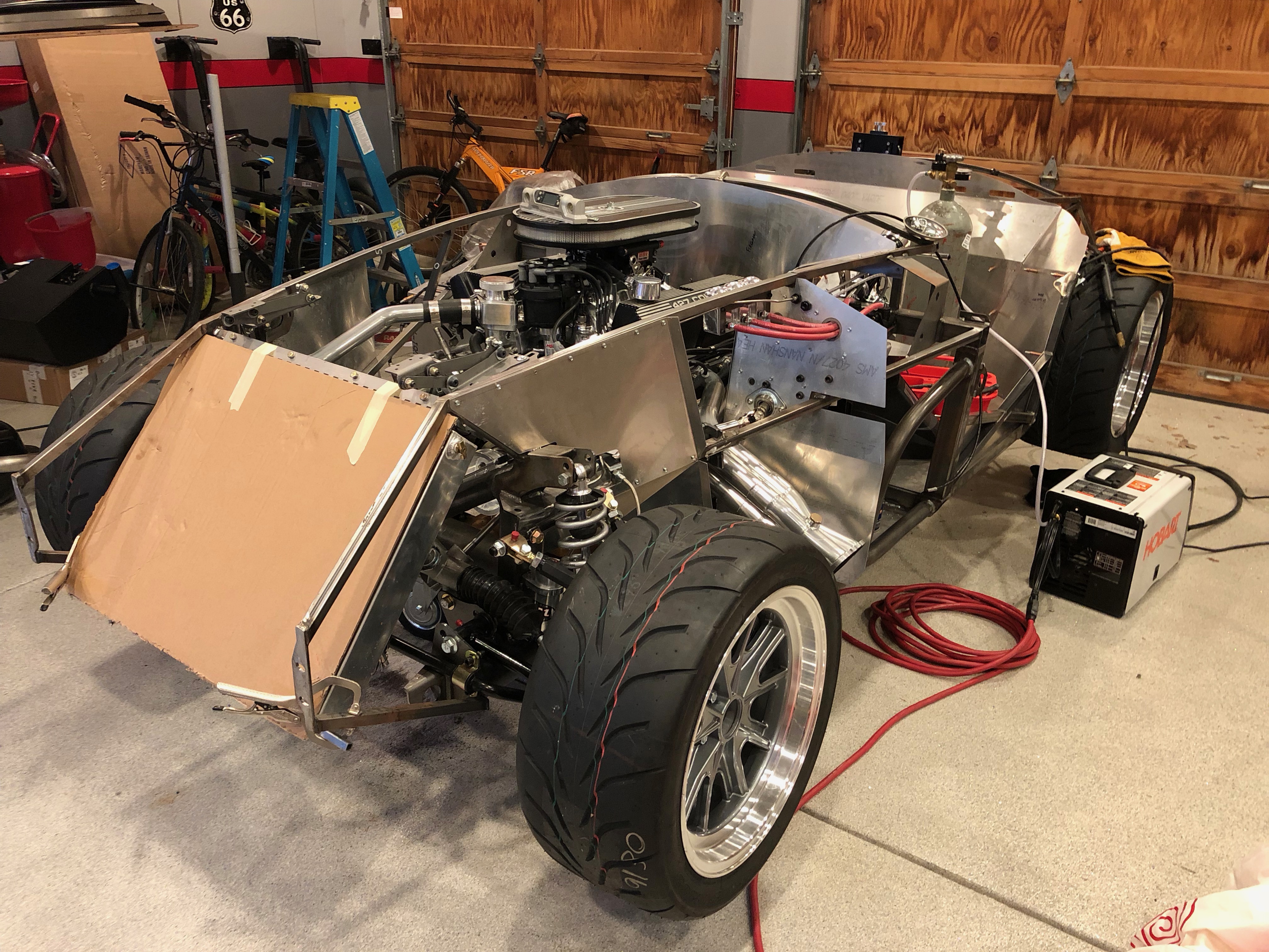
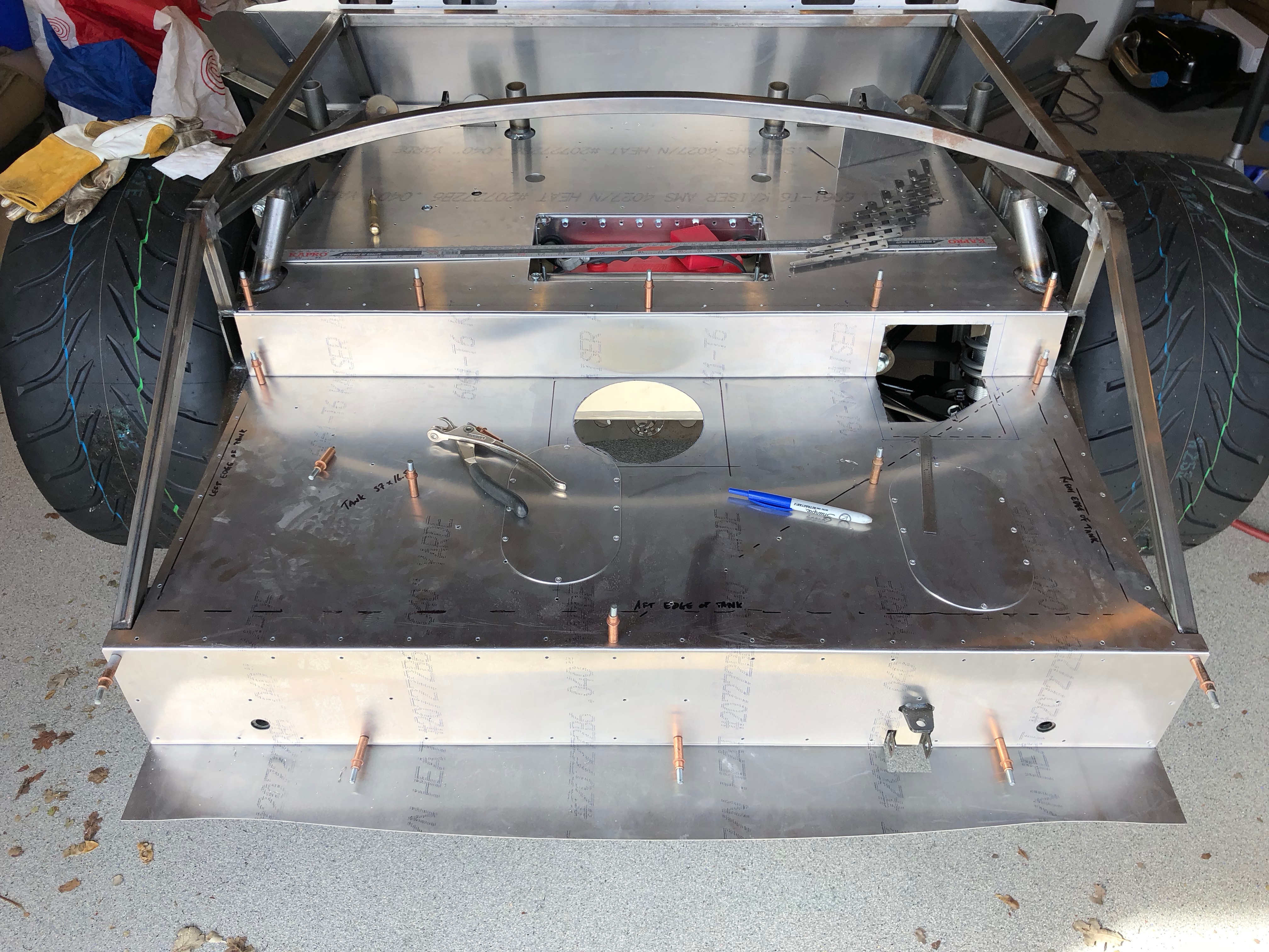
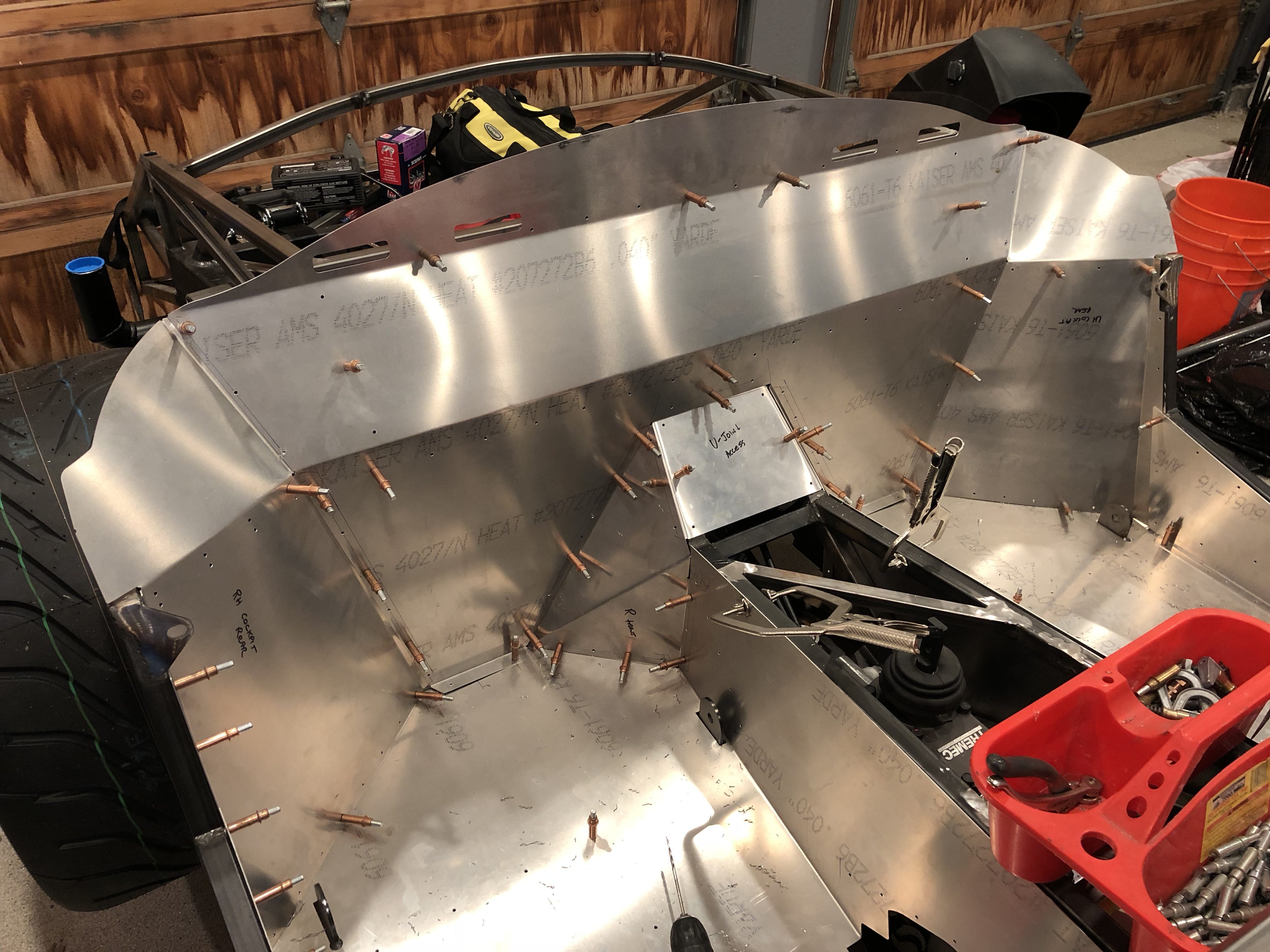
Here’s a shot of the whole vehicle. When you look at it like this, it doesn’t look like there has been much progress in the last few months, but there are a lot of details that are lost at this scale.

Rear Brake Line

After I boogered up the rear brake line last night, I decided to reroute it to simplify the necessary bends. When I first fabricated the rear brake line, I hadn’t installed the battery box, so I wanted to keep it tight to the other tubing. Now that I know where everything sits, I realized that it wasn’t necessary to have such a complex routing. The new routing has the brake line turn straight up from the fitting on the right side. It’s hard to tell from this picture, but the line is completely behind the inner CV boot. Even at full compression travel, I don’t think the inner CV boot could ever flex as high as the brake line, but I wanted some lateral clearance as well.

I installed a couple of rivnuts on the angled square tubing to secure the brake tubing where it crosses the chassis.

The second brake line clamp is on the left diagonal square tubing.

I put the tee in the vertical leg on the left side. I haven’t figured out which direction I’m going to have the third leg go from here, but it won’t interfere with any part of the suspension or drivetrain regardless of the direction.

Trunk Aluminum, Fuel Tank Stabilizers and Rear Brakes

Before I can install the fuel tank for good, I also needed to wrap up the trunk aluminum. I had previously drilled the upper trunk floor, but I never did the same for the lower trunk floor. I started by removing the tank (hopefully for the last time before the final reassembly). I needed to do this so that I could mark the chassis tubes on the underside of this sheet. After laying out all of the holes, I drilled the sheet to the chassis tubes. You can also see that there is a row of rivet holes tying the upper trunk floor to the lower trunk floor.

With the lower trunk floor in place, I cut and bent a piece of scrap aluminum to make the access panel cover for the fuel sender and fuel return and vent fittings.

I drilled this to the floor with a #30 bit for now. I’ll open these up for the right size screw before installing nutplates.

I also cut out and drilled an access panel cover for the fuel pump and supply fittings.

The fuel tank is narrower than the cavity in the chassis that it fits within, but I don’t want the fuel tank to be able to slide from side to side. To prevent this, I drilled a 1/4″ hole in the lower diagonal tube on the inside face and welded on a 1/4-20 nut.

I threaded a leveling foot with threaded stud into the nut. I had previously bonded a piece of the same reinforced rubber sheeting onto the foot where it will contact the tank.

You can see on the other side that there is a run nut threaded onto the shaft as well. Once the tank is installed, I can tighten the foot against the tank and lock it into position with the jam nut.

Before reinstalling the tank, I wanted to wrap up the rear brakes. I started by adding a brake line clamp on the right diagonal tubing. Unfortunately, when I was trying to wrap up the other end of this piece of tubing, I botched the flare. I don’t think the tubing is salvageable, so I’ll probably have to fabricate a new piece.

Fuel Tank Straps and Trunk Aluminum

After reshaping the fuel tank straps to better fit the angles of the new fuel tank, I used some contact adhesive to bond some strips of reinforced rubber sheeting to the inside surfaces where it will contact the tank.

While waiting for those to cure, I installed the outer trunk side skins. After marking the chassis tubes, I laid out for the rivet holes and drilled them to the chassis.

Cockpit Rear Wall and Emergency Brake Hole Cover

I finished drilling the rear wall to the upper cross member and adjacent aluminum panels.

Since I’m moving the emergency brake, I needed to make a cover for the old opening. The kit comes with two different front panels for the driver’s side foot box, so I took the unneeded one and cut a piece off the bottom to cover the hole. I’ll match drill this to the existing holes that tie the transmission side panel to the chassis and add some additional holes around the perimeter.

More Cockpit Aluminum

I continued working on the cockpit aluminum by fitting the rear outer panel on the driver’s side.

I then drilled the u-joint cover plate to the chassis and the rear inner panels to the cover plate.

Finally, I drilled the rear wall to the floor and the lower steel cross member on the chassis. I still need to drill this to the inner and outer rear panels and the upper steel cross member.

Forward Brake Line Clamps

I installed four of the single-line 3/16″ clamps from Lodestone BilletWorks to secure the brake line where it crosses the x-frame. These are custom clamps that fit the 2″ diameter tubing. The only unfortunate thing is that the screw holes aren’t drilled perpendicular to the radiused back. This causes the clamp to not want to sit flush with the tubing. There’s enough give that it sorta works out, but these could be better.

Continued Passenger Cockpit Aluminum

I continued fitting the aluminum around the passenger side of the cockpit. I temporarily fit the rear outer panel.

The flange on the seat floor needed to be bent out slightly to align with the rear outer panel.

After laying our some holes, I drilled it to the seat floor flange and chassis.

I then fit the small, rear inner panel on the passenger side and drilled it to the seat floor and side of the transmission cover.

Finished Drilling Passenger Foot Box and Seat Floor

I laid out and drilled the holes that tie the inside of the passenger foot box to the forward transmission tunnel cover and seat floor and then drilled the holes that tie the side wall of the transmission tunnel cover to the forward transmission tunnel cover.

The inside wall of the passenger foot box can still move around a bit, so I used some welding magnets to lock it into position so that I can figure out where to cut the floor and where to mount the angles.

While I had the seat floor out, I laid out some holes that will tie it to the transmission tunnel. I still need to fabricate a cover for the old emergency brake access hole.

I laid out a few additional holes near the back of the seat floor.

InfinityBox inRESERVE Installation

I’ve been contemplating where to mount the InfinityBox inRESERVE components and finally settled on the right side of the battery box. This will provide a short run from the battery positive terminal to the 350A mega fuse (since that is an unprotected wire).

I decided to put the fuse below the latching solenoid to avoid a super-tight bend in the cable from the battery to the fuse. There is a jumper from the other side of the fuse to the side of the latching solenoid.

I cut a 2.25″ long piece of the 2/0 wire and crimped terminals on the ends with the appropriate clocking to mate to the terminals.

I then installed a piece of the heavy-duty heat shrink tubing over the whole assembly. This is essentially rigid now.

Finally, I slipped a couple of boots over the terminals.

After reinstalling the jumper, I drilled and bolted the components to the side of the battery box with some short 1/4-20″ bolts.

While I had the battery box out, I drilled out the holes that pass the battery cables and installed larger rubber grommets. Now the wires can be installed without removing the grommets.

I reinstalled the battery box (hopefully for the last time before final reassembly) and then fabricated and installed the positive battery cable. As you can see, there is a nice, gentle bend from where the cable comes out of the forward side of the battery box to the right side of the mega fuse and there is no way for this cable to contact any other structure in the car.

Inside the battery box, the battery positive cable makes a fairly sharp bend to turn toward the positive terminal. Just like the negative terminal, there is a right-angle terminal on the positive wire, but there is also a right angle protective boot to prevent any contact with the cover plate. I reinstalled the negative cable but will leave it disconnected for now.

You can also see in this picture that I’m temporarily using screws to attach the battery box to the chassis. The heads of these screws are too tall to allow the battery to be installed with all of them in place, so I only installed the aft screw (at the bottom of the picture) and then put in a handful of screws on the forward side of the box for now. After final reassembly, I’ll rivet the box in place and the rivet heads should not interfere with battery installation and removal.