Drilled Passenger Foot Box

The aluminum sheet that is normally installed as the floor of the foot boxes fits flush with the bottom of the round tubing that frames the foot boxes. The steel panels that I welded in sit slightly higher than that. This was pushing up on the forward and inside panels of the passenger foot box. I decided to cut off the pre-formed flanges in these pieces so that they could drop down into position. Here, I’ve cut the flanges off the inside panel to the left, but haven’t yet cut the flange off the forward panel to the right. After cutting all of these off, the panels fit much better in the car. I’ll fabricate some mounting angles and rivet them to both the floor and walls.

With the panels fitting much better, I laid out a series of holes along all of the edges and drilled the panels and chassis. I want to drill all of the intersecting panels before drilling this to the floor.

Installed Fuel Line Clamps

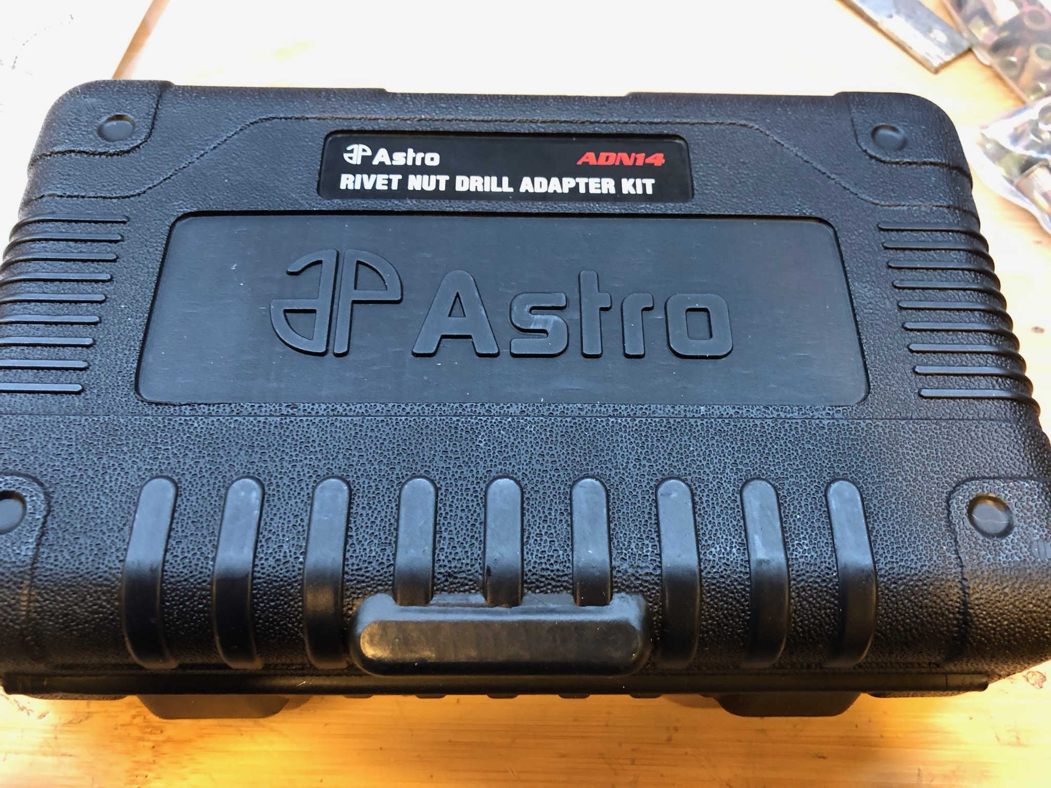
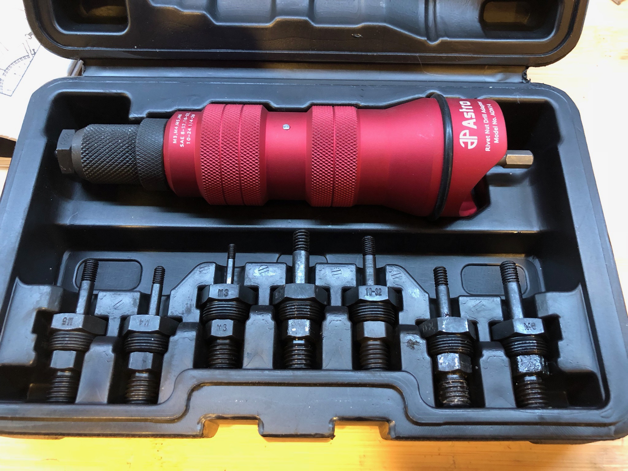
I received a new tool for Christmas from my awesome wife. I have a small hand tool that was fine for setting aluminum rivet nuts, but for the car, I really need to set steel rivet nuts and I knew that it wouldn’t do. This Astro rivet nut drill adapter is highly recommended and has great reviews online.

It’s a really nicely built tool. The body is machined from a solid block of aluminum and it has all chromoly internal components and mandrels for maximum durability. A cordless drill with a clutch is attached to the shaft on the right side and used to set the rivet nut.

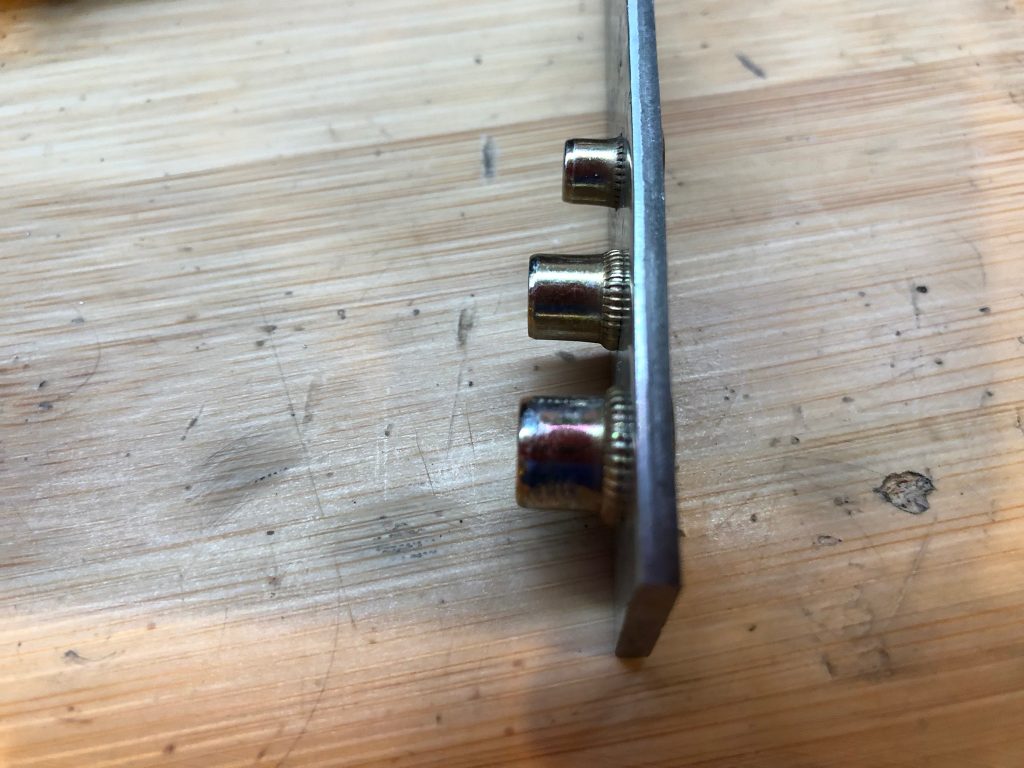
It has mandrels for 8 sizes of SAE and metric rivet nuts, but I’m only planning on using three sizes on the car 8-32, 10-24 and 1/4-20 (arranged from top to bottom). I set some samples in a piece of scrap steel to determine the correct torque setting on the drill. The 8-32 rivet nuts are a little short for this thickness of steel, but I’ll probably mostly use them in thinner metal.

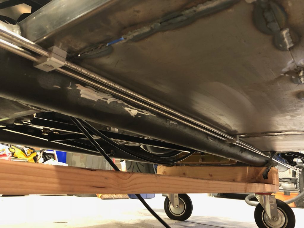
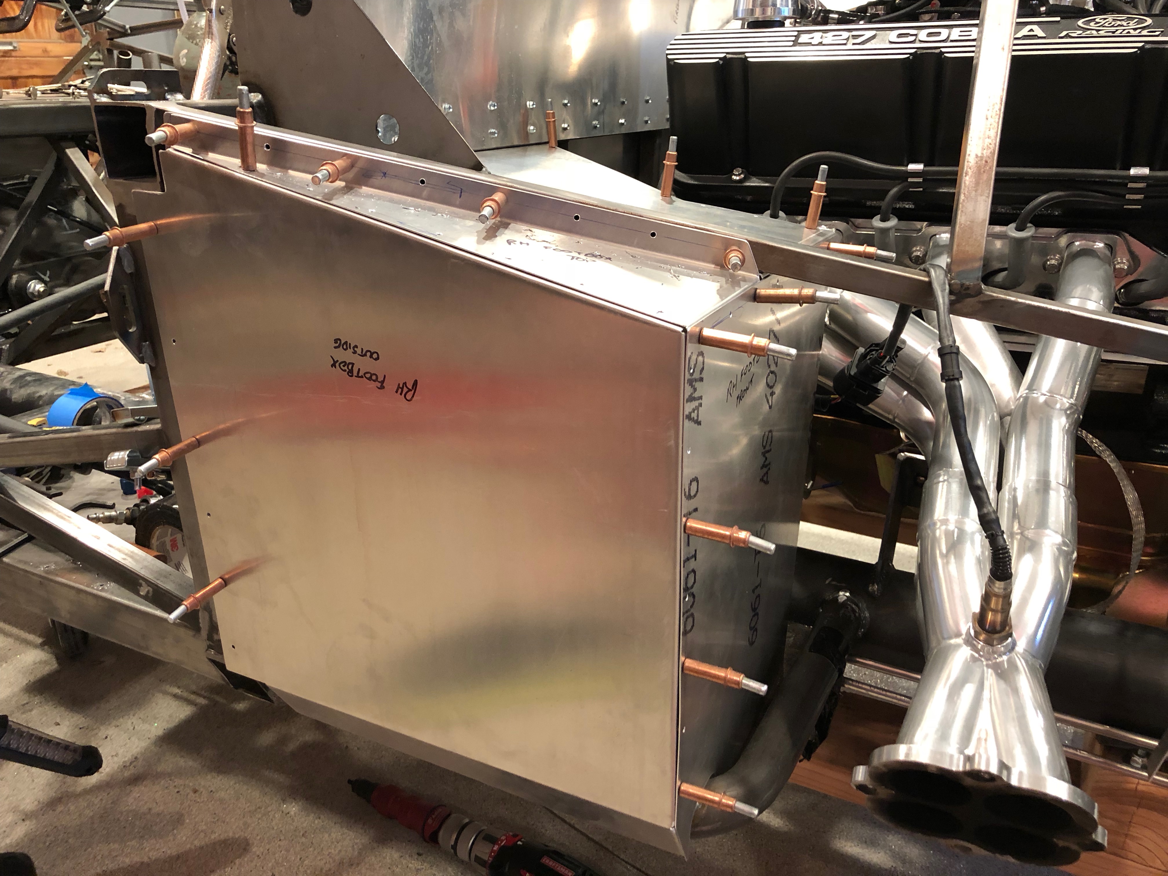
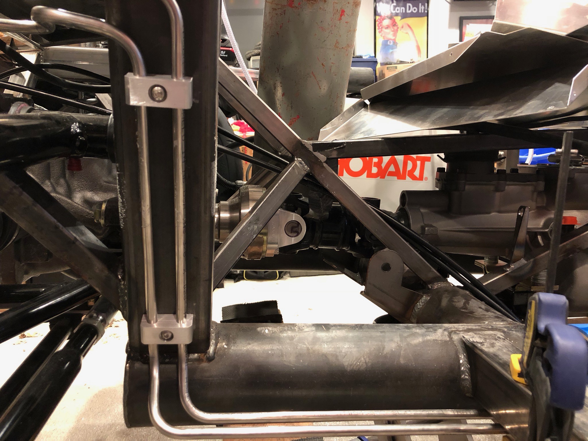
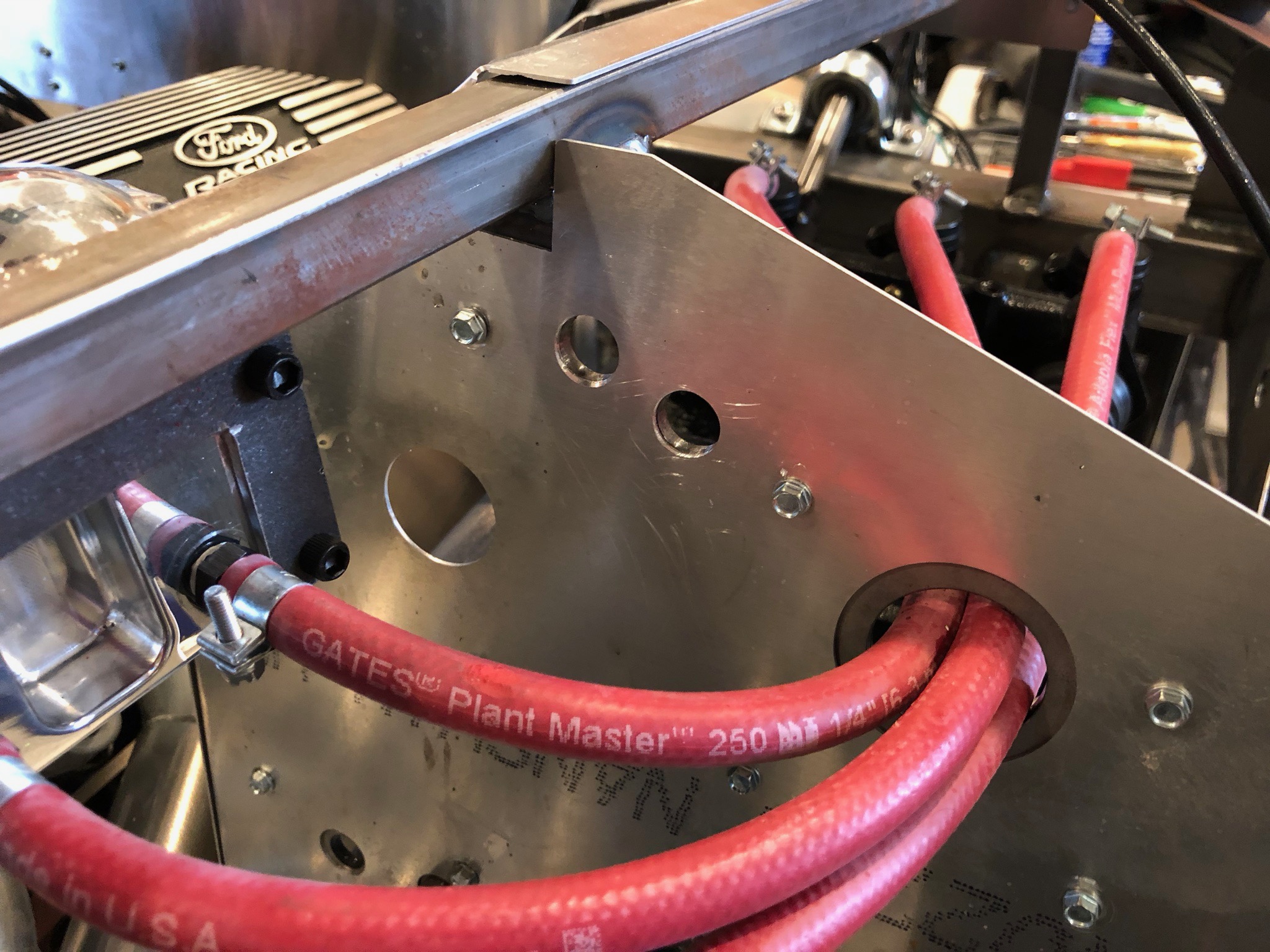
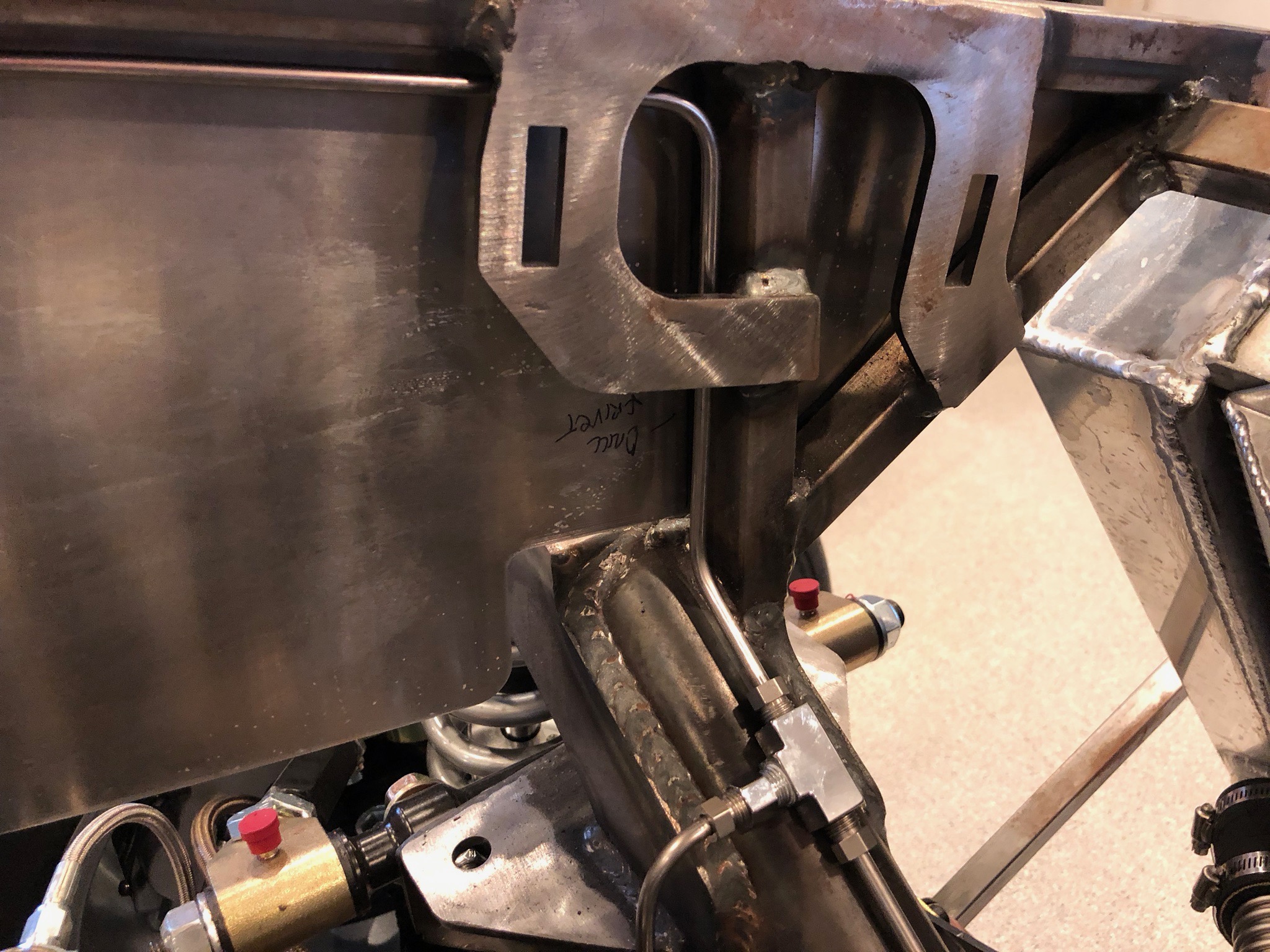
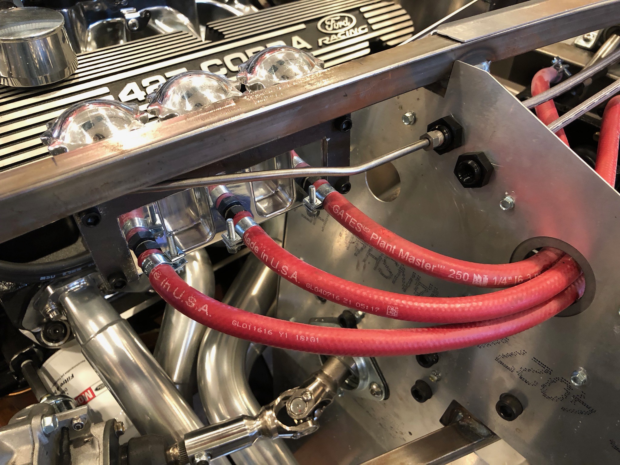
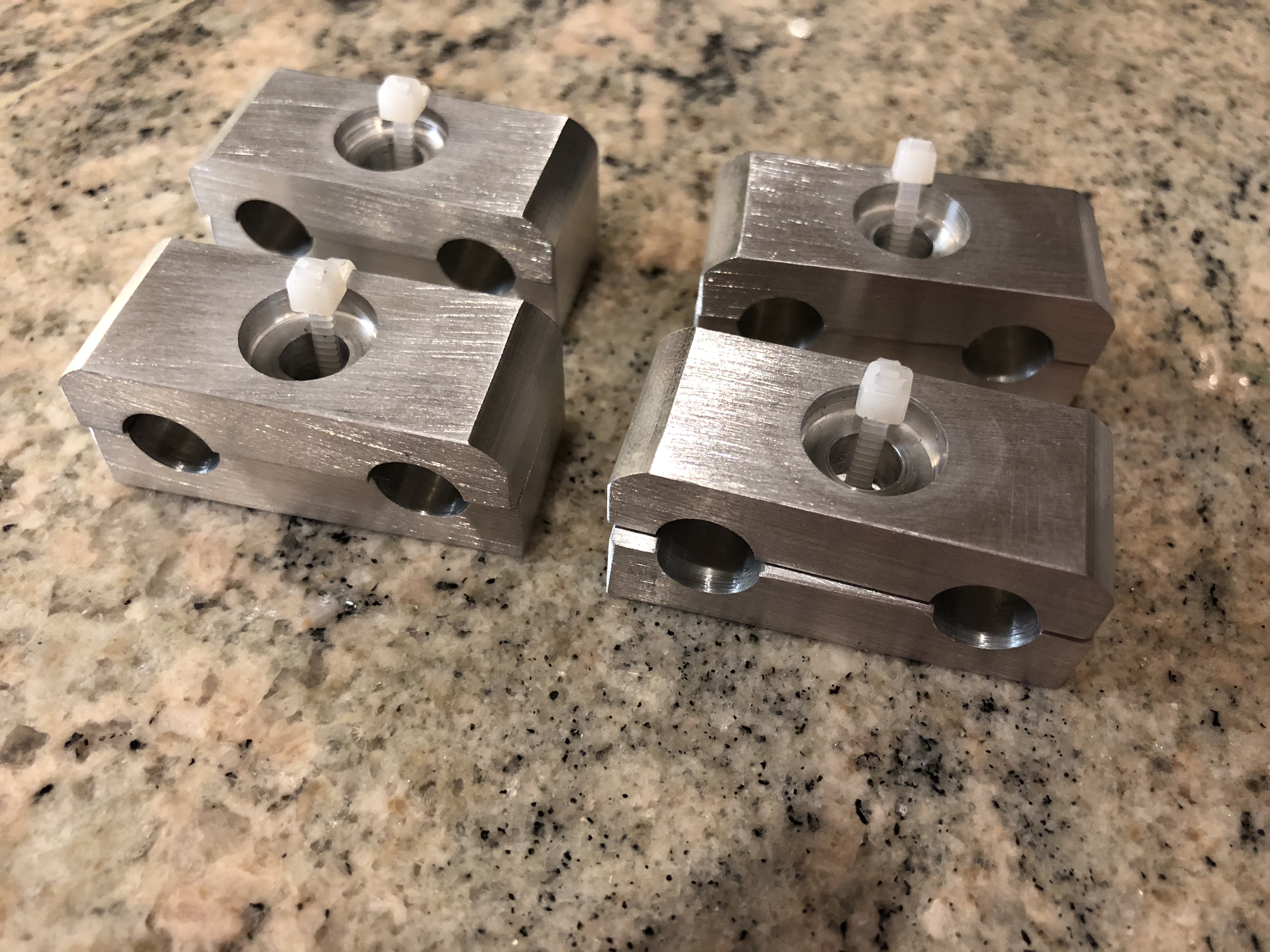
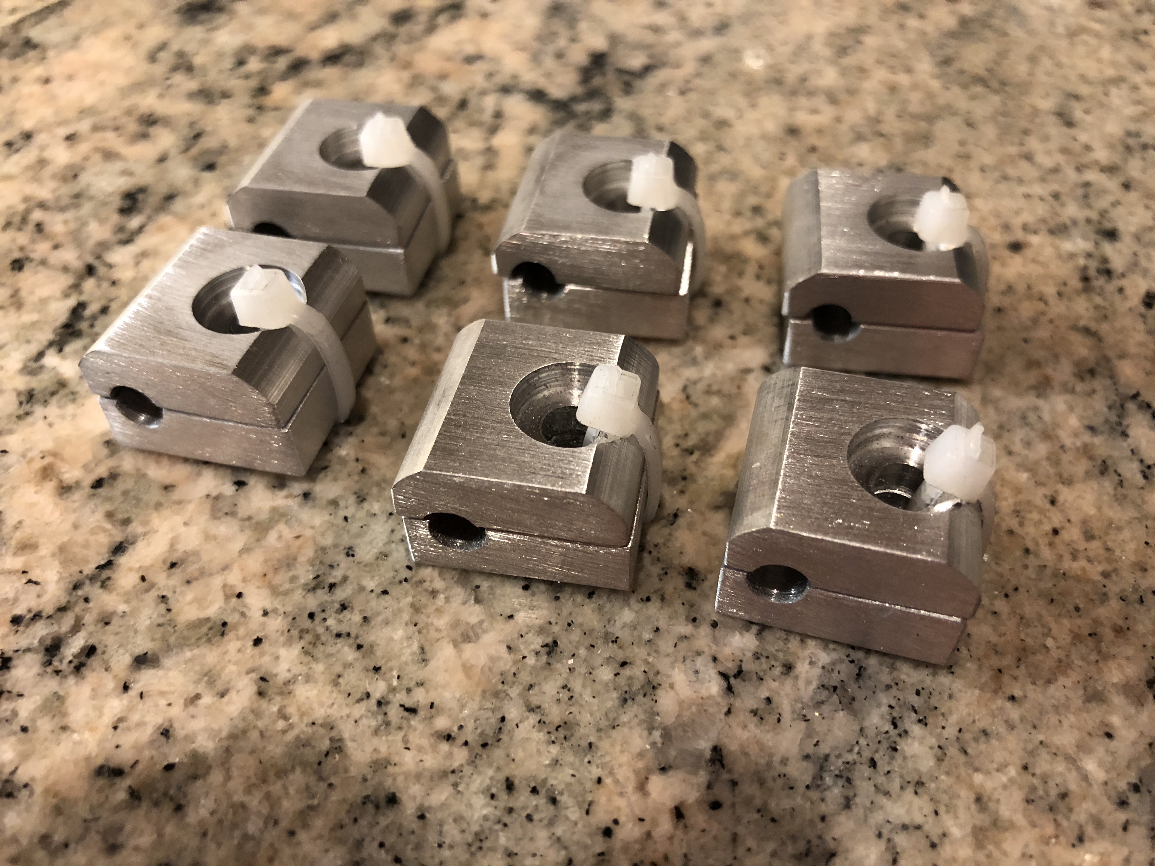
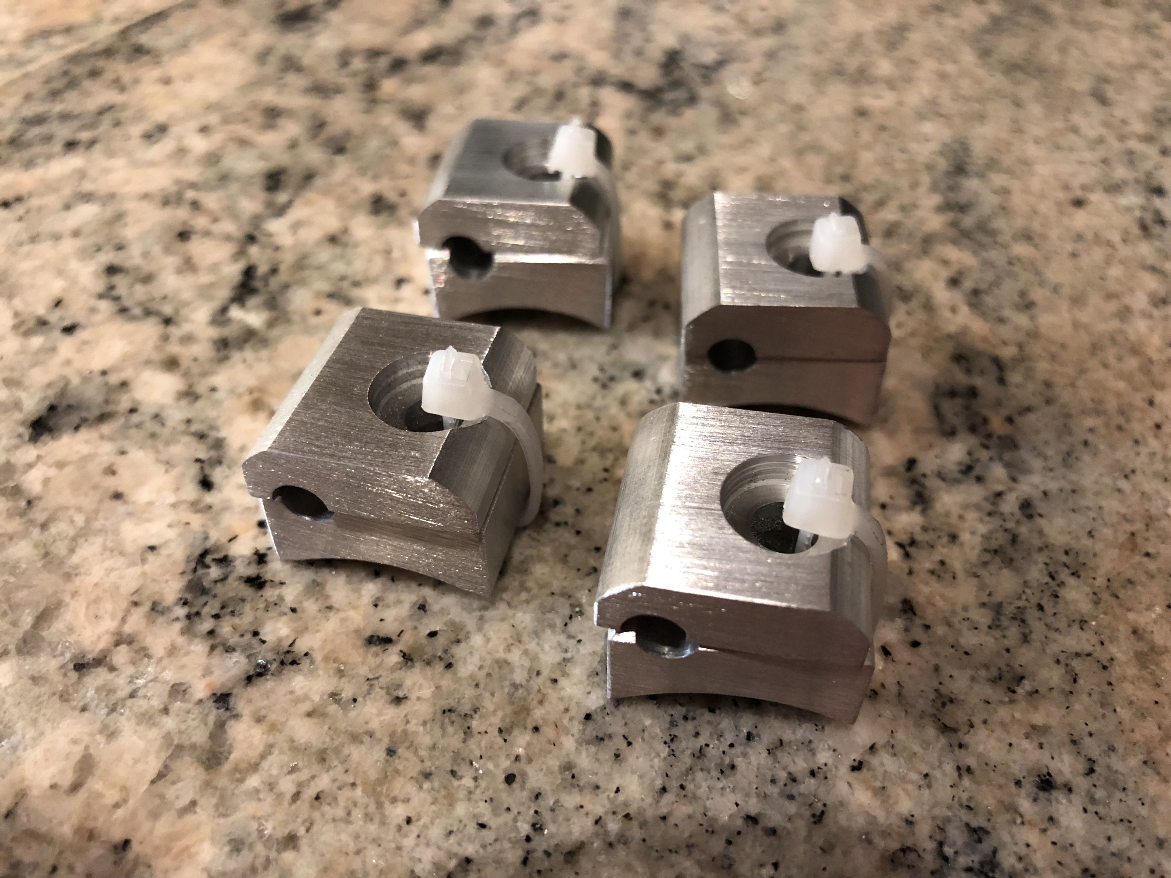
I’m using some billet aluminum clamps from Lodestone BilletWorks to secure the fuel lines to the chassis. I clamped a few on to determine where to drill for the rivet nuts.

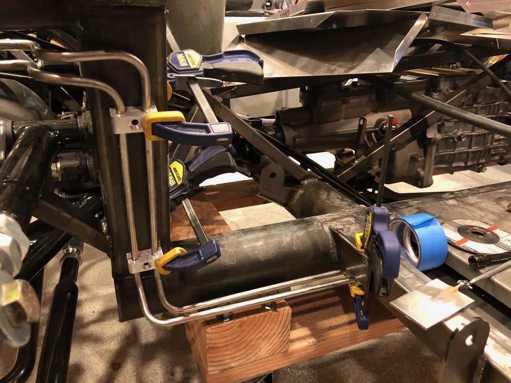
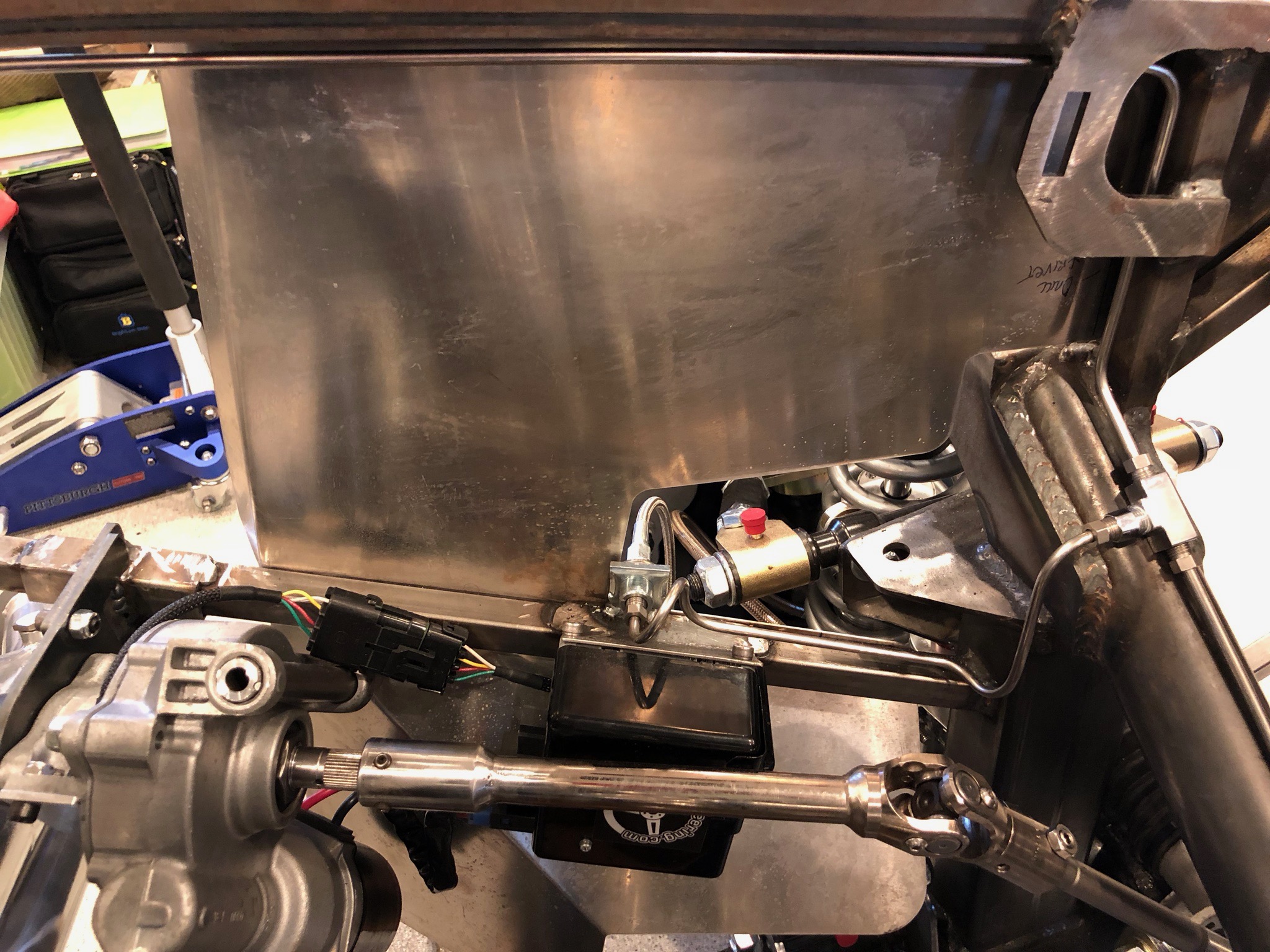
After drilling and setting a couple of rivet nuts, I secured the clamps on the vertical support so that I could determine the final position of the clamps under the passenger seat.

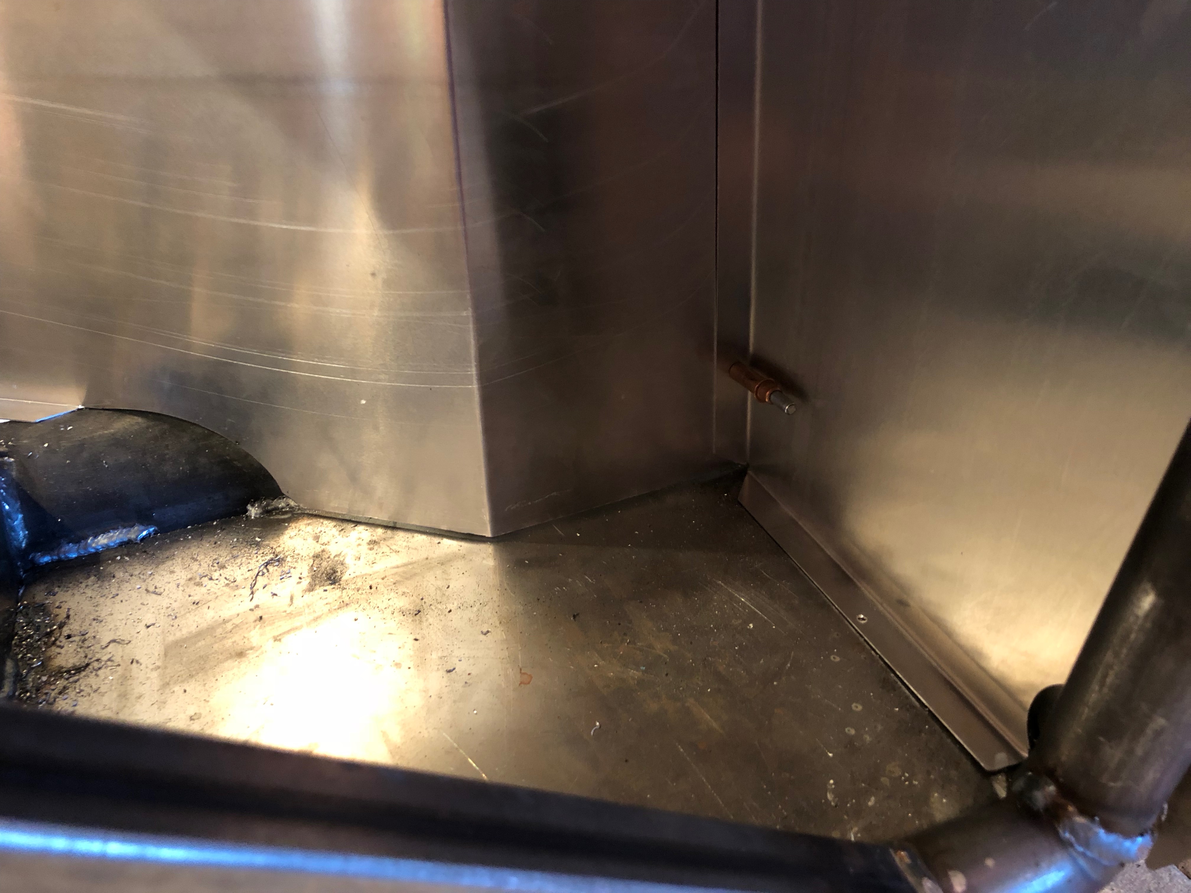
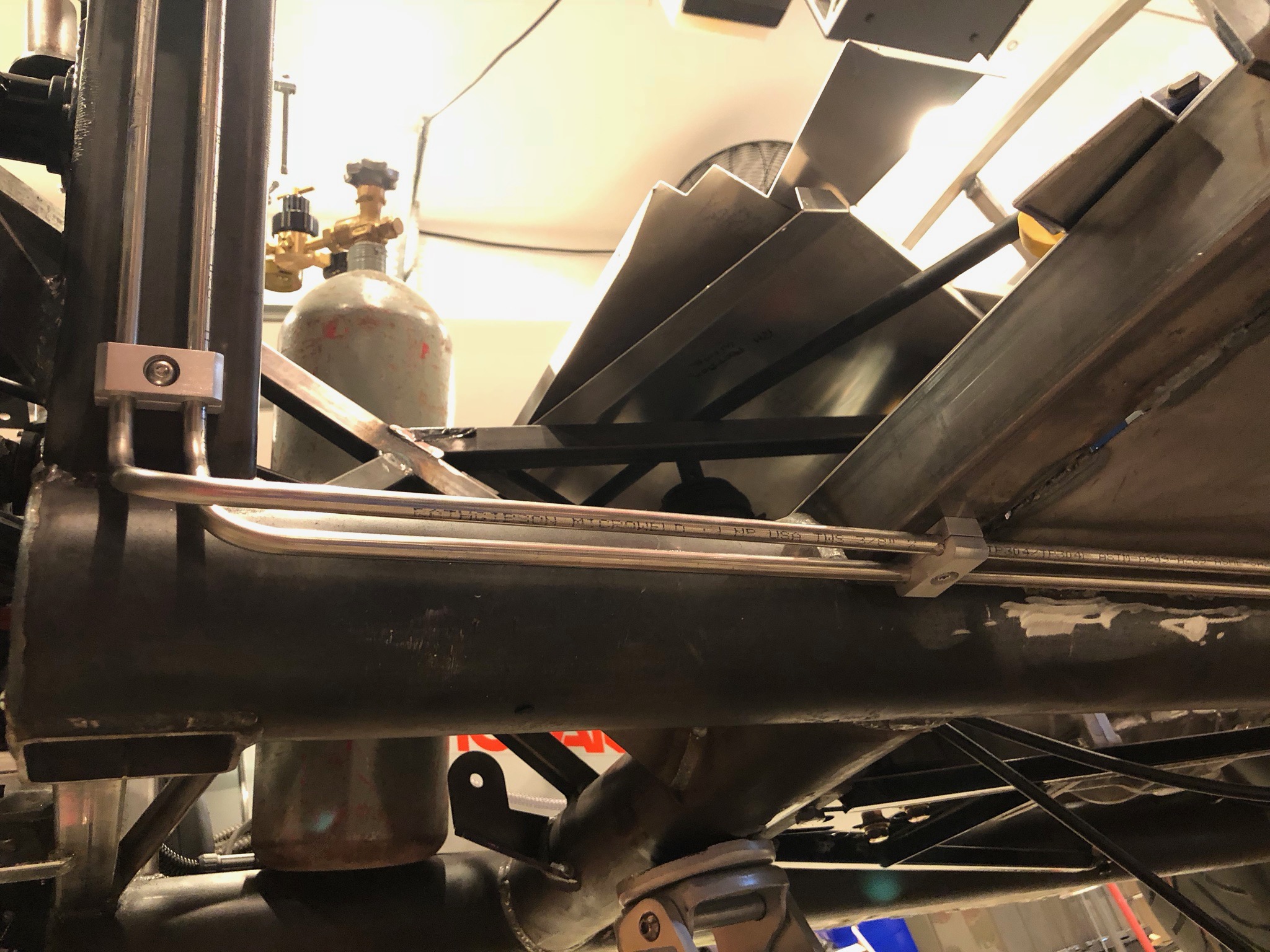
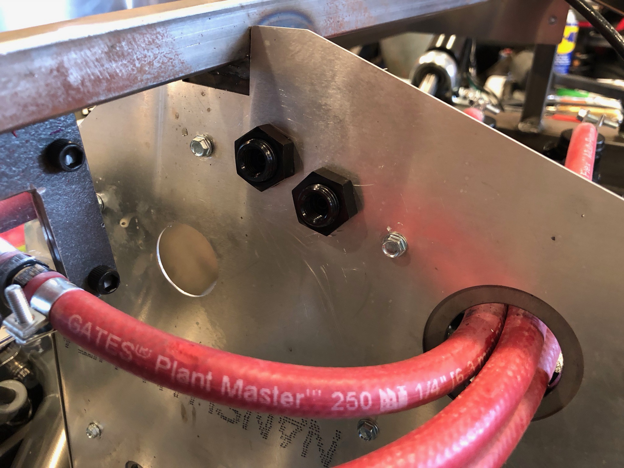
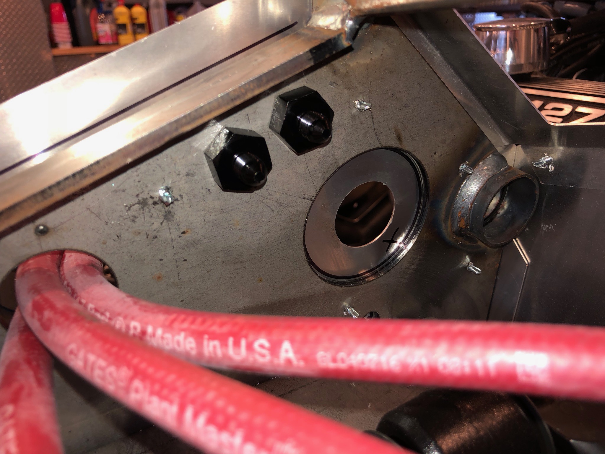
I drilled and installed a rivet nut in the horizontal tubing behind the passenger seat. I used the measurements from this hole to drill the corresponding hole in the horizontal tubing in front of the passenger seat.

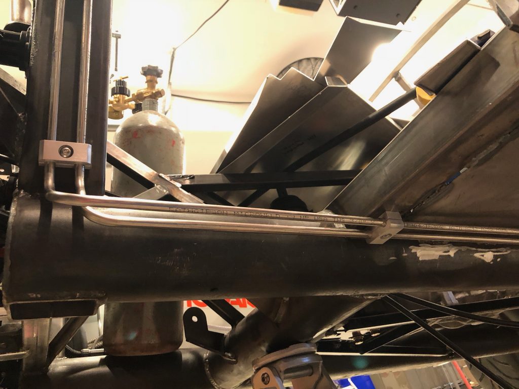
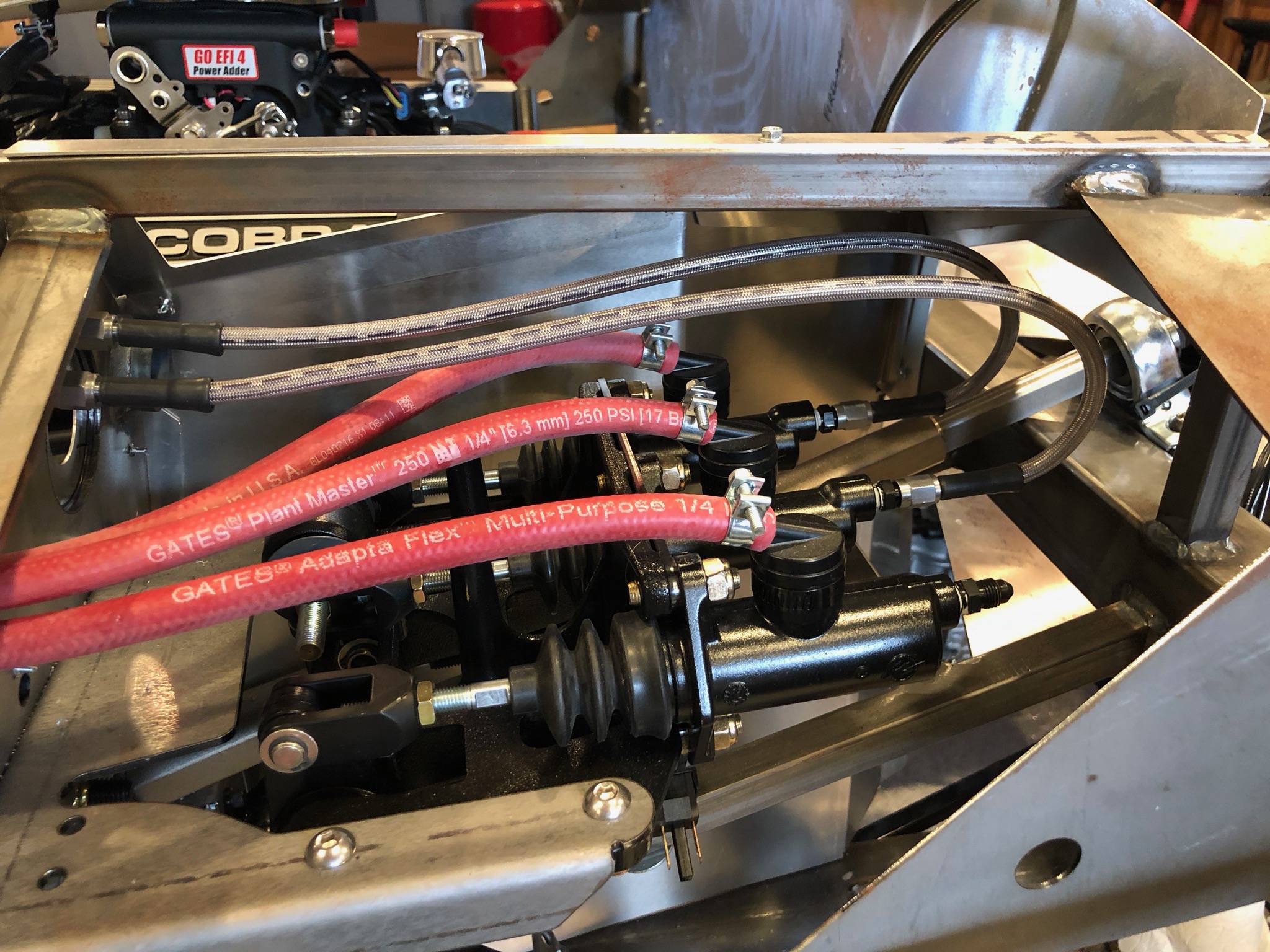
I’m not sure yet whether two clamps under the passenger seat will be sufficient or if I’ll need to add an additional clamp or two. The 3/8″ stainless tubing is pretty stiff, but it sounds like other builders space them closer together (and some state regulations require it).

Hung Flags

We’ve had a few flags that I’ve been meaning to put up in the shop, but I needed to move the other wall art, so I kept putting it off. I decided to tackle that today, so I pulled the old decorations off the wall, patched a painted the wall and hung up the flags. The Shelby Cobra flag has the preeminent spot. Partially hidden behind the lift and gas pipe is a Ford Performance flag.

On the other side of the lift, we have our Porsche flag.

Finished Front Brakes

I need to transition from the brake master cylinders to the 3/16″ stainless tubing that routes to the front and back of the car. I could have routed the stainless tubing all the way to master cylinders (and that was my original plan), but I decided to keep all flex hose inside the driver’s foot box and transition to the rigid tubing at the front of the foot box. I got started by drilling a couple of 9/16″ holes.

I installed a couple of bulkhead fittings. These have an inverted flare fitting on the forward side…

…and a -03AN fitting on the back side.

I then connected a couple of -3 hoses from the master cylinders to the bulkhead fittings.

I only needed one more line to finish up the front brakes, so I measured and made the first couple of bends to tuck the line behind this bracket and up against the bottom of the square tubing at the top of the picture.

That upper square tubing has a gentle curve to it, so I bent the line to follow it. I’ll ultimately add a clamp of some sort along here to secure this.

Behind the brake/clutch reservoirs, the line bends to line up with the bulkhead fitting.

Installed Steering Wheel Hub

The upper steering shaft has two flat sides that can only fit into the steering wheel hub two ways, but the steering wheel can install in six different positions. Normally it’s not particularly important how the upper steering shaft is oriented since any misalignment of the steering wheel can easily be adjusted at the tie-rod end during wheel alignment.We’re using

We’re using Russ Thompson’s Turn Signal System which requires machining the hub so that it has protrusions to trip the self-canceling feature of the steering column. This means that the upper steering shaft’s two flat sides need to be oriented vertically when the steering rack is centered. Just my luck that it was oriented exactly 90º out from that. While I might have been able to adjust the tie rods enough to center the steering wheel, I really didn’t want the tie rods adjustment to be that uneven between sides.

Instead, I loosened all of the splined joints and bearings on the steering shaft enough that I could uncouple the upper spline joint (just forward of the driver side foot box) and rotated the upper steering shaft 90º. I then tightened everything back down and installed the steering wheel hub. I fully seated it on the shaft by using the center bolt to draw it down and then tapped the shaft in until the gap between the steering hub and steering column was about 1/8″. Finally, I verified that the self-canceling feature works as expected. All I need to do now is install the steering wheel and the steering system will be complete. I’m going to hold off on installing the steering wheel for a while though to avoid scratching it.

Minimal Progress

There has been little progress on the car over the last few weeks. Work has been busy and I’ve had a bunch of work to do on several of the other cars in our fleet. I also re-published my RV blog which has been busted for a while and we’ve been swamped with prep for the holidays.

All of that work is done now, so I should be able to start working on the car again.

Received Tubing Clamps

We also received some tubing clamps from Lodestone BilletWorks. These clamps are for the 3/8″ fuel supply and return lines.

I also ordered a bunch of single, 3/16″ clamps for the rear brake line. I may need more of these because I need to put them closer together because of the smaller size of the tubing.

I also ordered four of these with a 1″ radiused back to support the front brake line where it follows the x-frame.

Battery Ground Cable

The black heat shrink tubing showed up today, so I crimped on the battery terminal and applied heat shrink tubing to each end.

I reinstalled the ground cable and hooked it up to the battery. The cable has to make a pretty sharp turn to exit the box, so I may reverse the cables or make a different exit hole.

Ordered InfinityBox

I’ve been working on our electrical system configuration for weeks now and we’re finally happy with the plan. We’re installing the following items from InfinityBox:

  • InfinityWire 20-circuit Wiring Harness

  • inDASH MAX Dash Lighting Module

  • inLINK RF Control Module

  • inRESERVE Active Battery Monitoring

This will let us control the following electrical circuits in the car:

Front

  • High-beam headlights
  • Low-beam headlights
  • Parking lights
  • Turn signals
  • Hazard lights
  • Ignition
  • Starter
  • Heater
  • Horn
  • Radiator fan
  • Electric Power Steering

Back

  • Brake lights
  • Parking lights
  • Turn signals
  • Hazard lights
  • Seat heaters
  • Stereo
  • Interior lights
  • Trunk light
  • inRESERVE solenoid