We haven’t been able to install the shift ball because the threads in the ball (M16x1.5) don’t match up with the shift lever (M12-1.75) and the ball didn’t come with the right adapter. I contacted Epco Manufacturing (the maker of the shift ball) over a week ago but still haven’t received a response, so I ordered one from Summit.
Finished Hole in Floor
Resumed Work on Fuel Lines
I resumed work on the fuel lines tonight and got started by fabricating the fuel return line. I used a special 90º swivel fitting with 1/2 NPT threads instead of installing a 1/2 NPT to -6 AN adaptor and then a 90º AN fitting on the hose becase this doesn’t stick up as far. Even this sticks above the top of the fuel tank by nearly 1/2″, and the trunk floor is only 3/4″ above the top of the trunk. I made the hose about 1/2″ longer than necessary to put a small bend in it. This will prevent the hose from being pulled tight if the tank moves around a bit.
The return line connects just below the supply line with the filter.
The fuel lines run just outside the right main 4″ chassis tube. I briefly considered bringing them up in front of the passenger foot box, but that would put them very close to the right exhaust header. Instead, I marked and began cutting a hole in the passenger foot box floor to bring the fuel lines up farther back and farther away from the exhaust headers. The cut lines follow the inner wall of the passenger foot box. I’ll fabricate some flanges to rivet the wall to the floor along these edges.
I cut the fuel lines just aft of this hole and flared them for some fittings. I’ll fabricate some shorter tubing sections later to run from here up behind the engine in the engine bay. There will be hose segments connecting the rigid tubing to the engine to allow for engine movement.
Starter and Alternator Wiring
I installed the 2/0 AWG starter cable tonight. It starts at the output side of the mega fuse and follows the right parking brake cable forward to the aft end of the transmission tunnel.
It crosses over to the left side of the tunnel and then up the left side past the shifter and then cuts back to the right at the forward end of the tunnel.
It travels down the diagonal tunnel support member and then attaches to the starter. I’ll secure this with adel clamps when I have run all the wires through the transmission tunnel.
I also installed a 4 AWG cable from the alternator to the starter. This is covered in black expandable sleeving and black heat shrink tubing in keeping with the color theme of the engine bay.
Reverse Switch, Fuel Filler, Coolant System and Electrical System
The Tremec reverse light switch looks like it has threaded studs, but these are just ribbed and use some oddball connector.
I removed it and replaced it with a GM 14014559 switch which uses a standard Weatherpak connector.
I installed the fuel hose and fuel cap just to prevent fumes from escaping and keep debris out of the tank.
I also got some new 90º silicone hoses from HPS Silicone Hoses. The forward one is 1.5″ on both legs and the aft one has one 1.5″ leg and one 1.75″ leg (for the water pump). After tightening the hose clamps, I filled the coolant system with coolant and filled the reservoir about half-way.
Finally, I printed some heat shrink tubing labels and added them to all of the wires on the load cells. Here’s the front load cell. Since the load cell is on the right side of the vehicle, I positioned the labels to be readable from above on that side.
I installed the rear load cell wire labels upside down since these can only be accessed from below once the trunk floor is installed.
Differential Vent, Battery Box, Fuel Tank and Electrical System
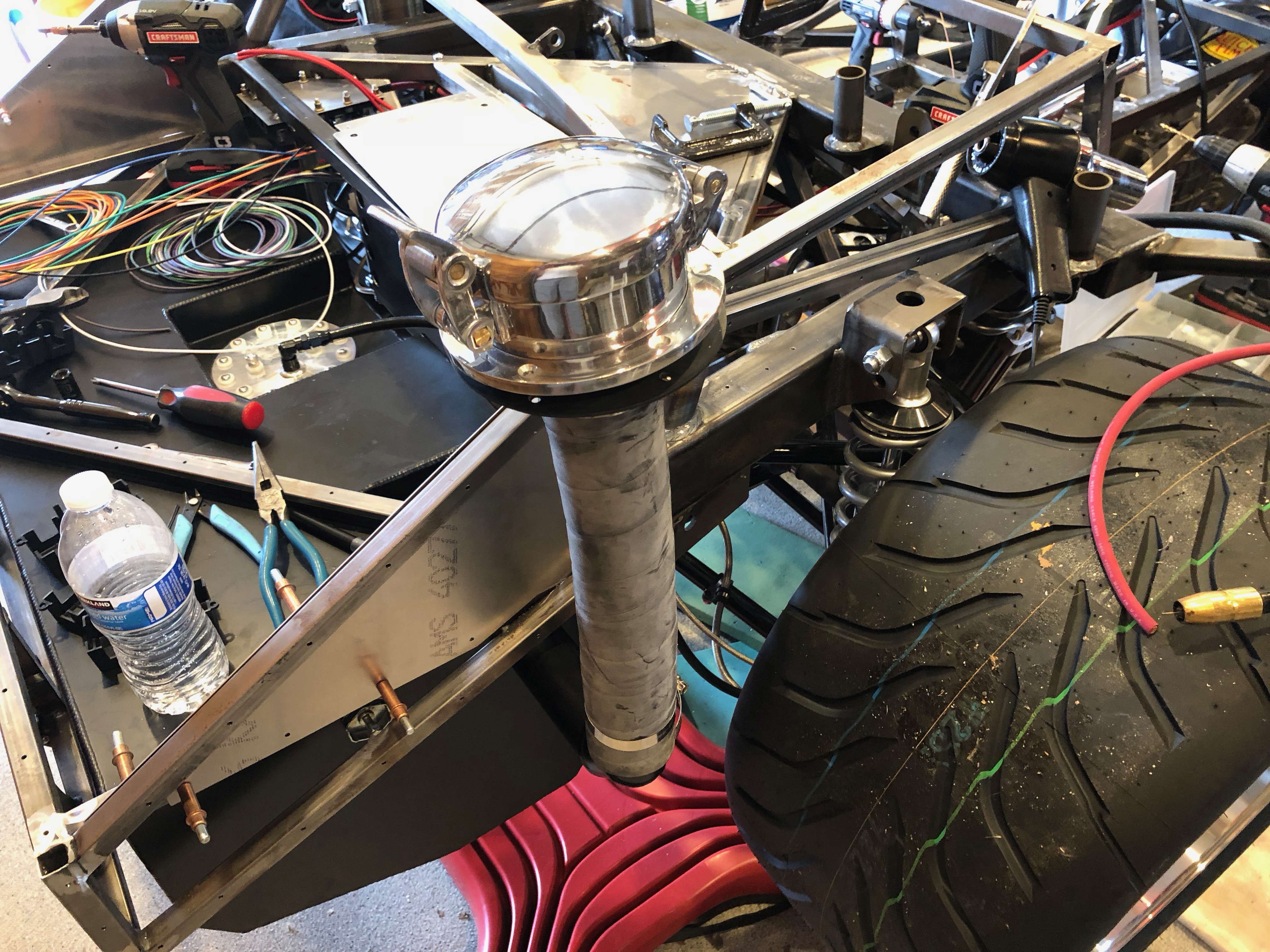
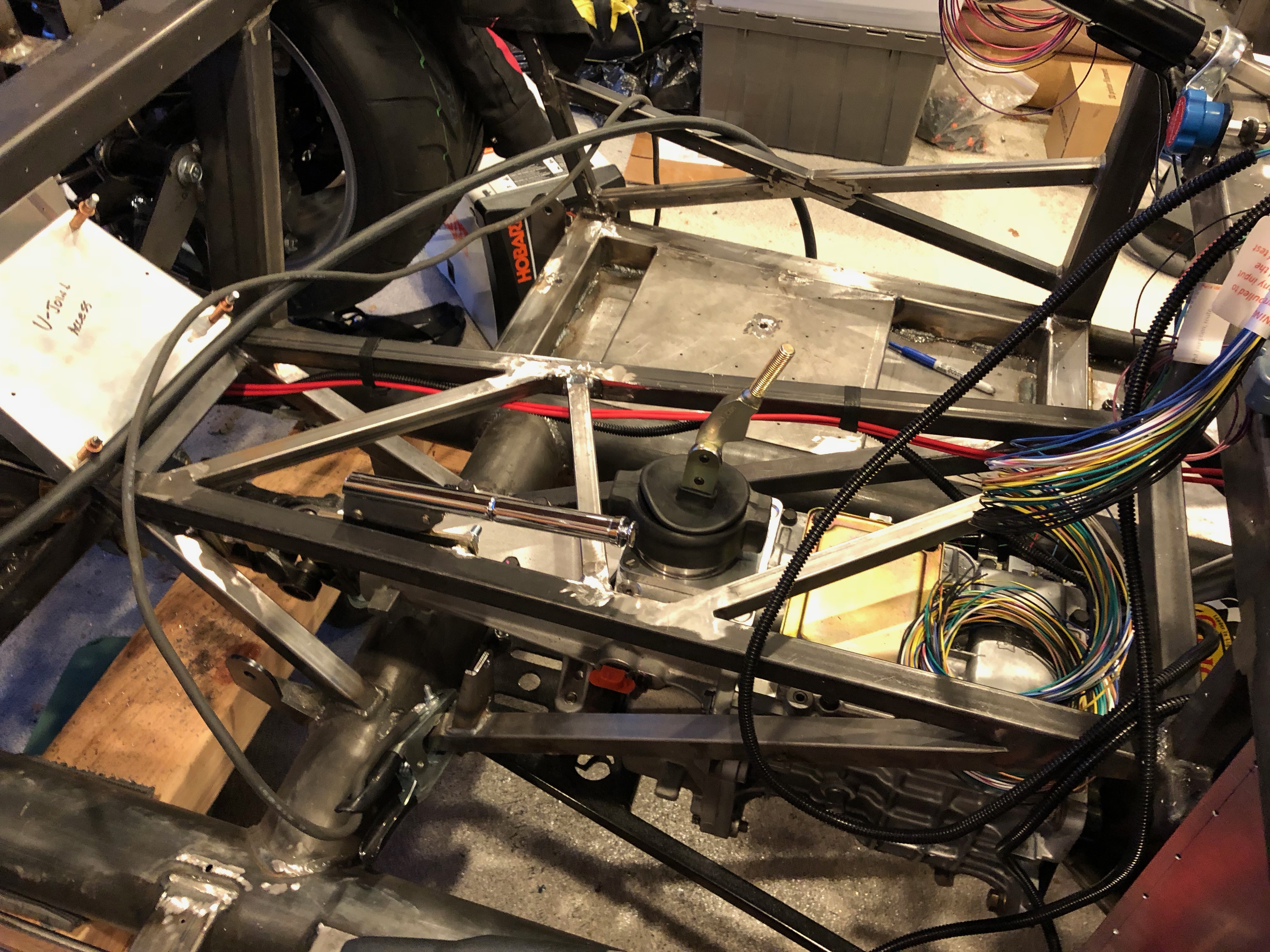
I finally received the differential vent fitting I’ve been waiting for. It’s a press in fitting (unlike the threaded fittings used on the solid axles). I used some high-temp thread locker and drove it in, then fit a vent riser with check valve at the top. I’ll use an adhesive zip-tie base to secure the top of this and keep it upright.
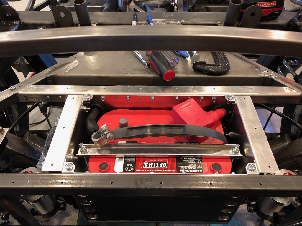
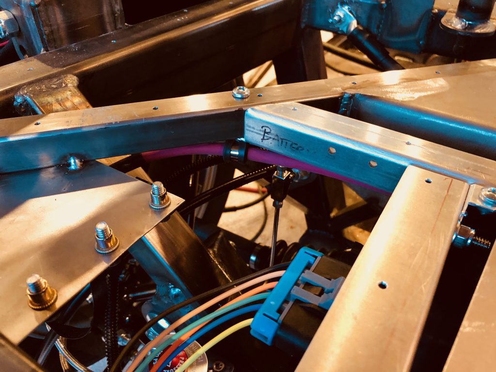
After installing the battery box, I reinstalled the battery (hopefully for the last time before the go-kart stage).
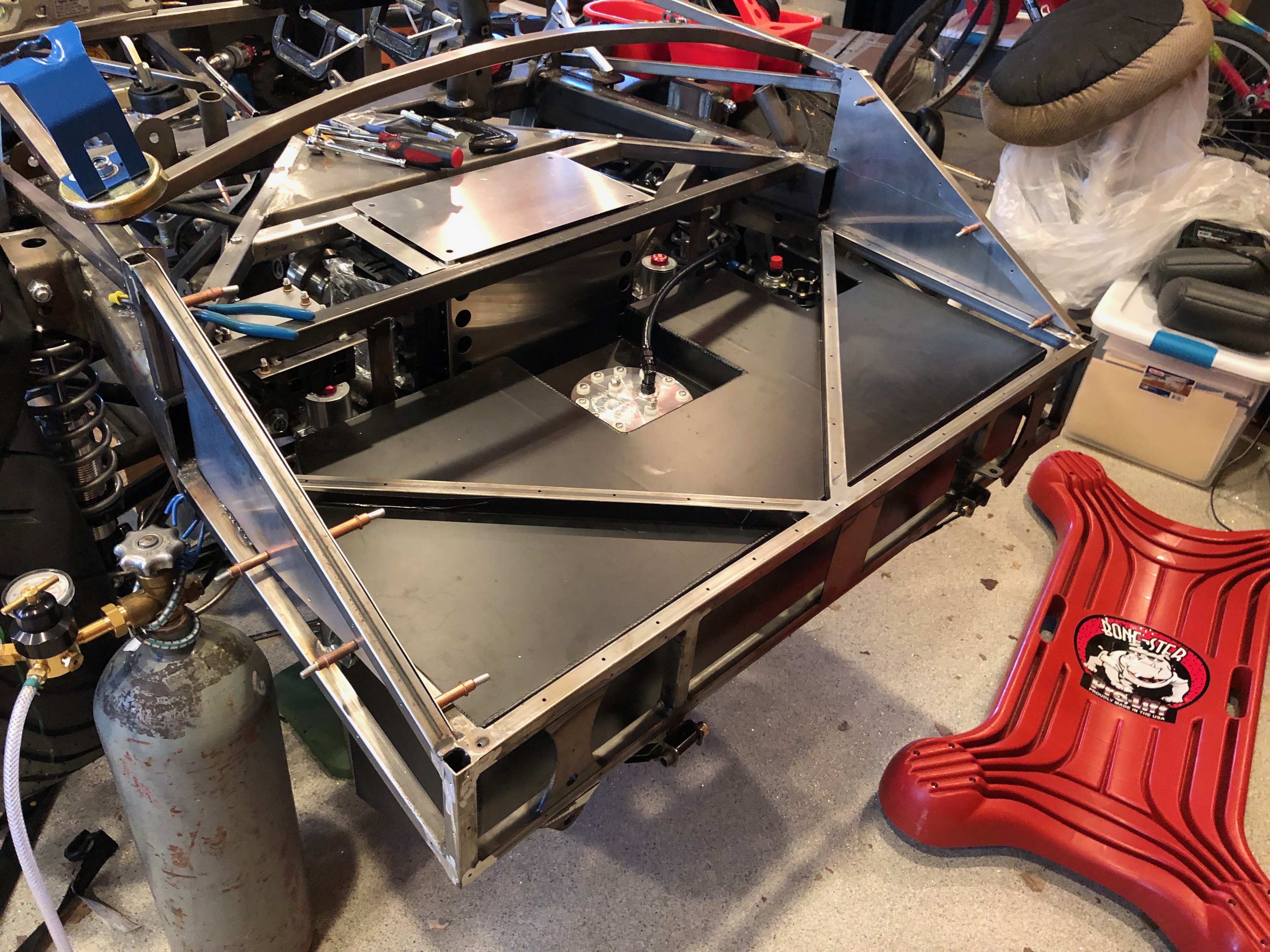
My dad and his friend Larry helped me lift the fuel tank and get the straps installed.
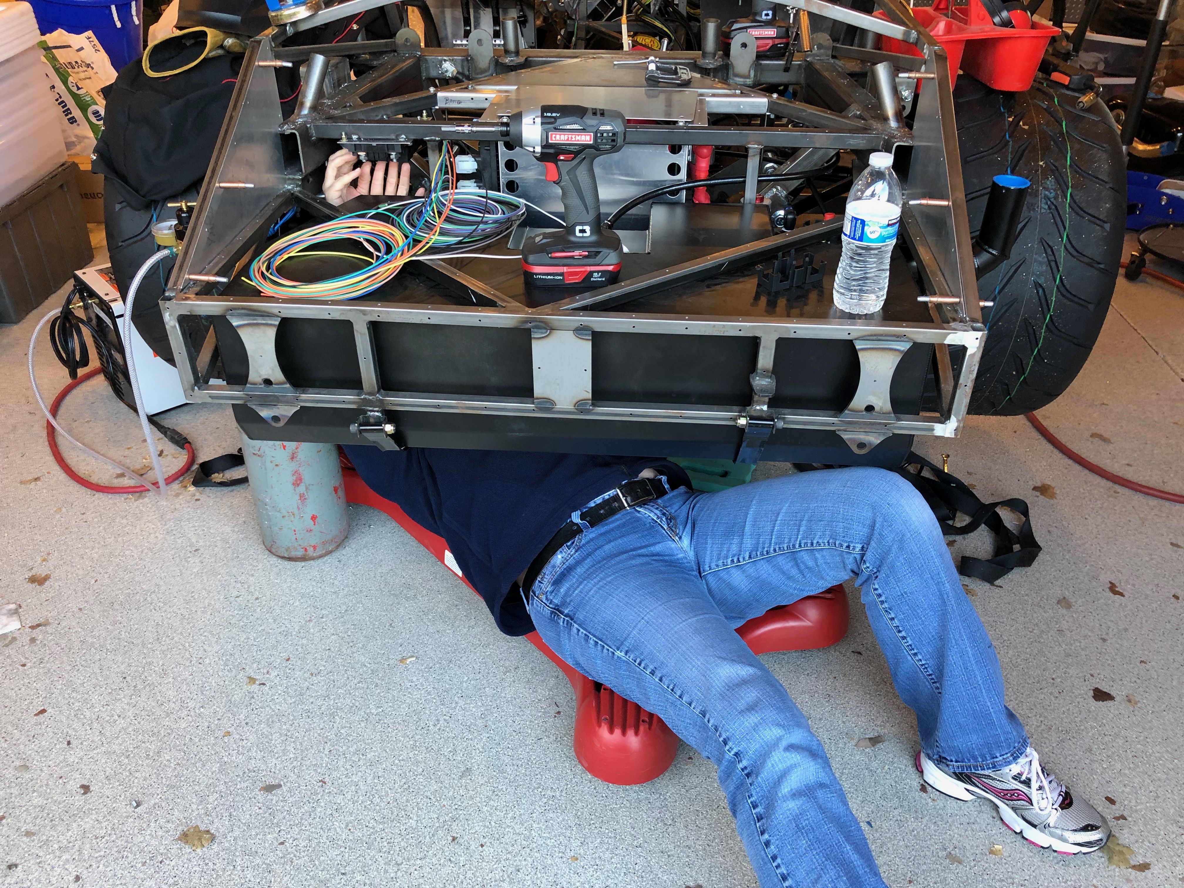
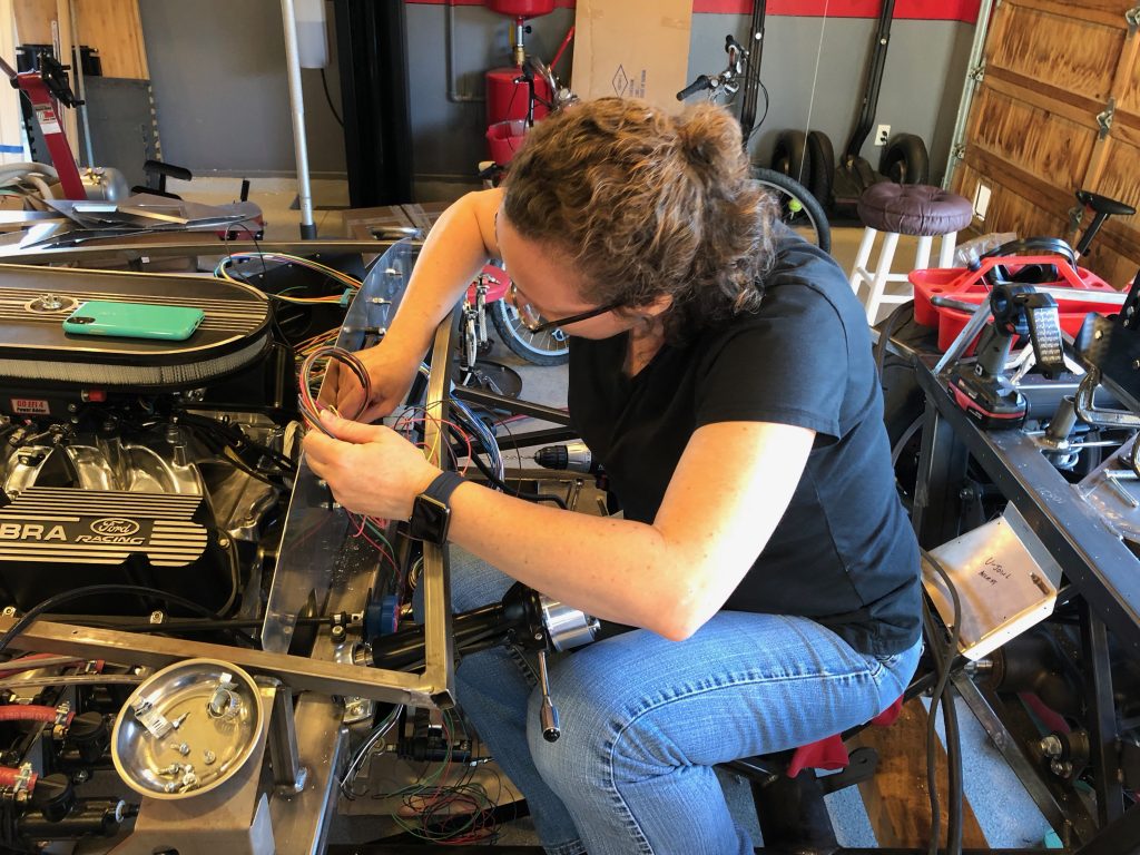
Jenn came out and we spent some time working on the electrical system. She crawled underneath the rear end so that she could hook up the power wire to the mega fuses.
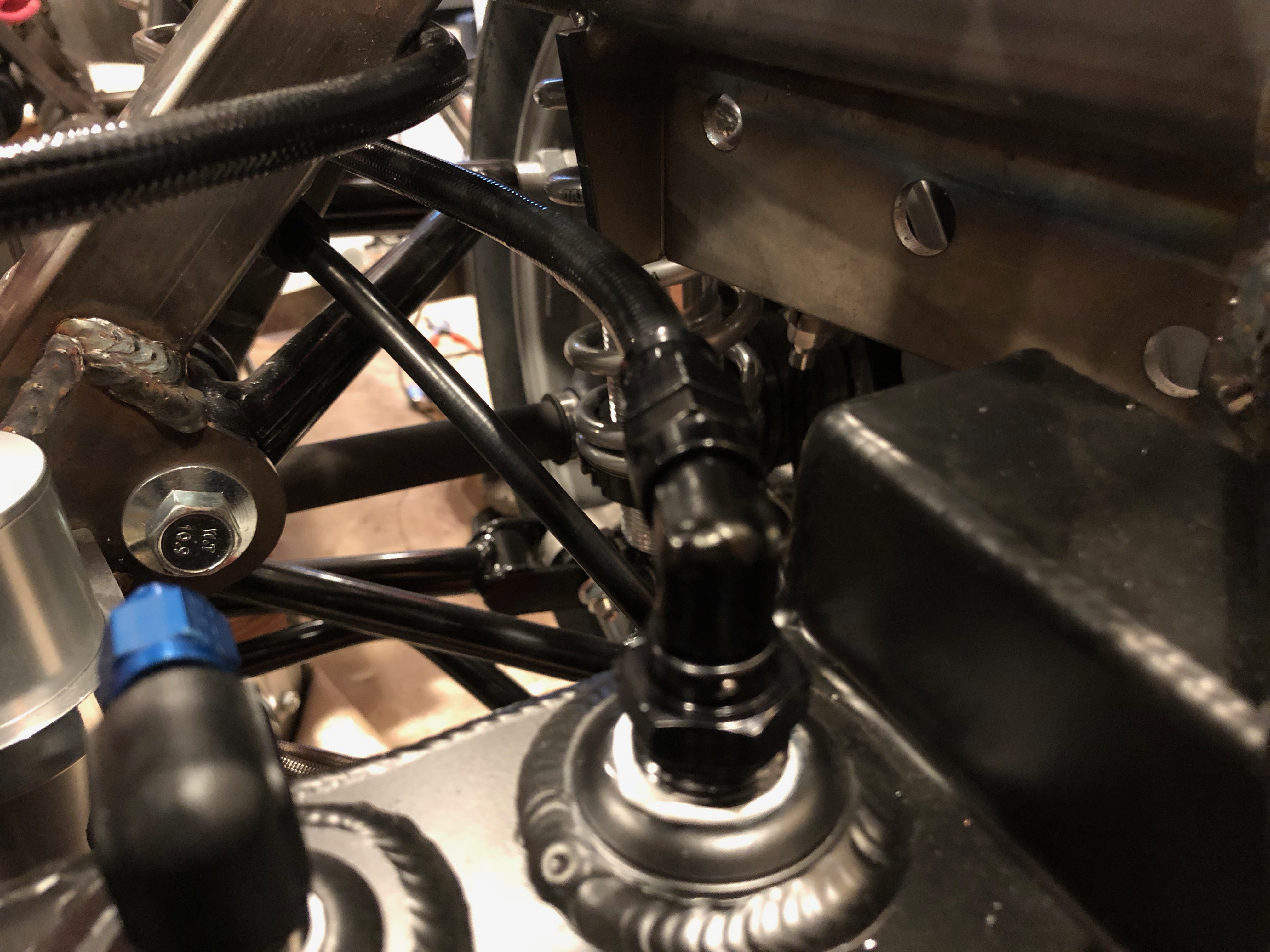
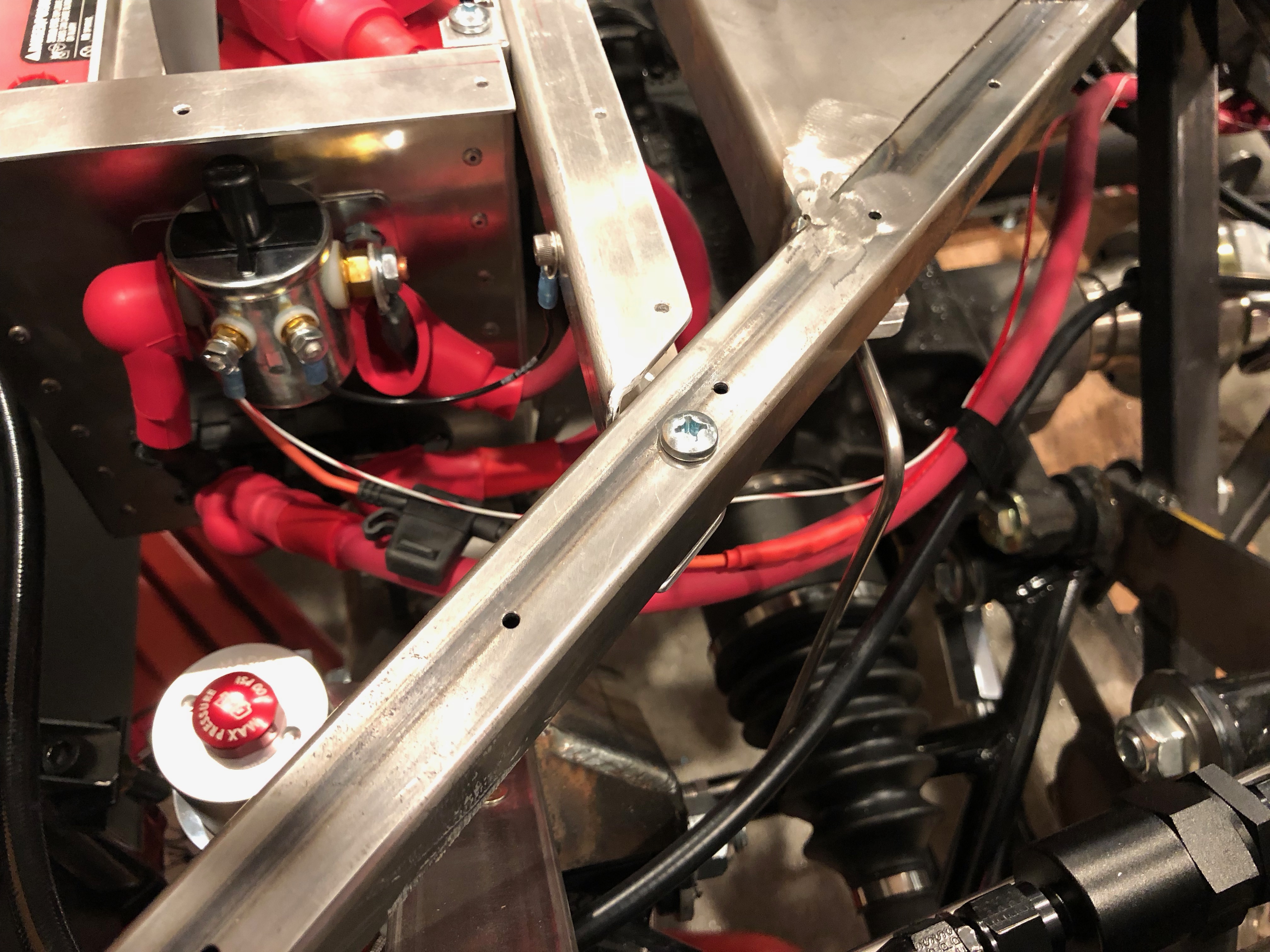
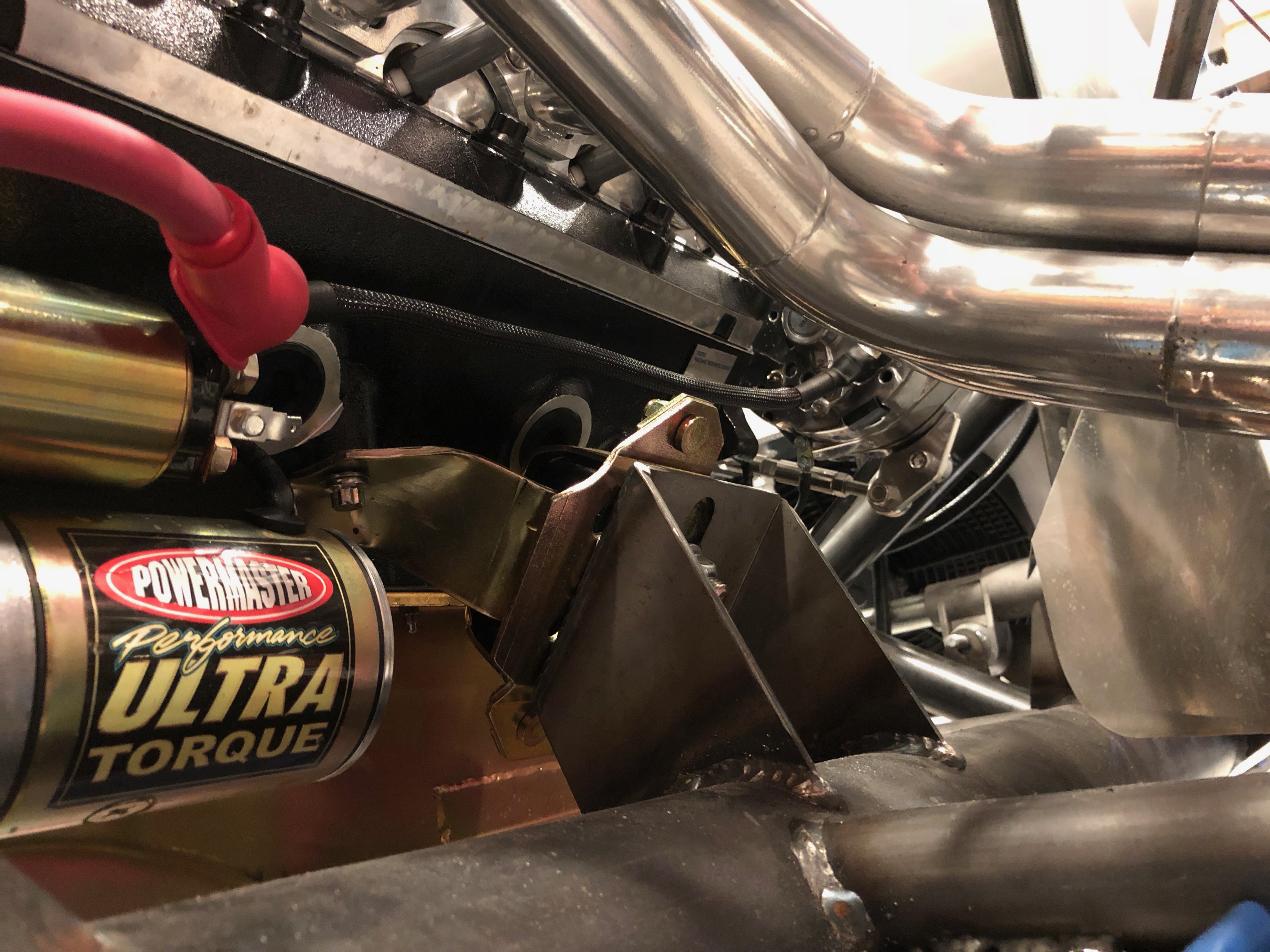
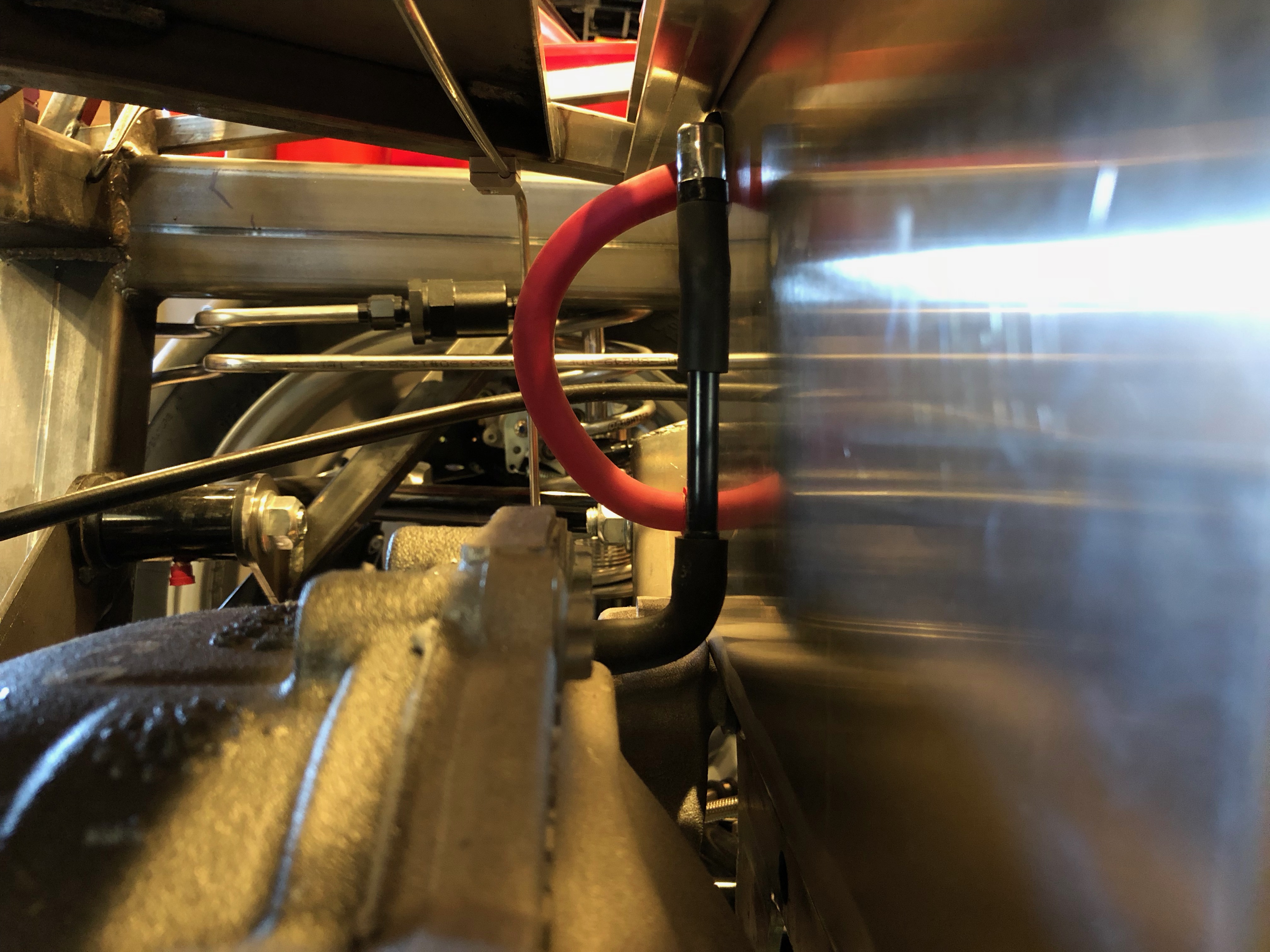
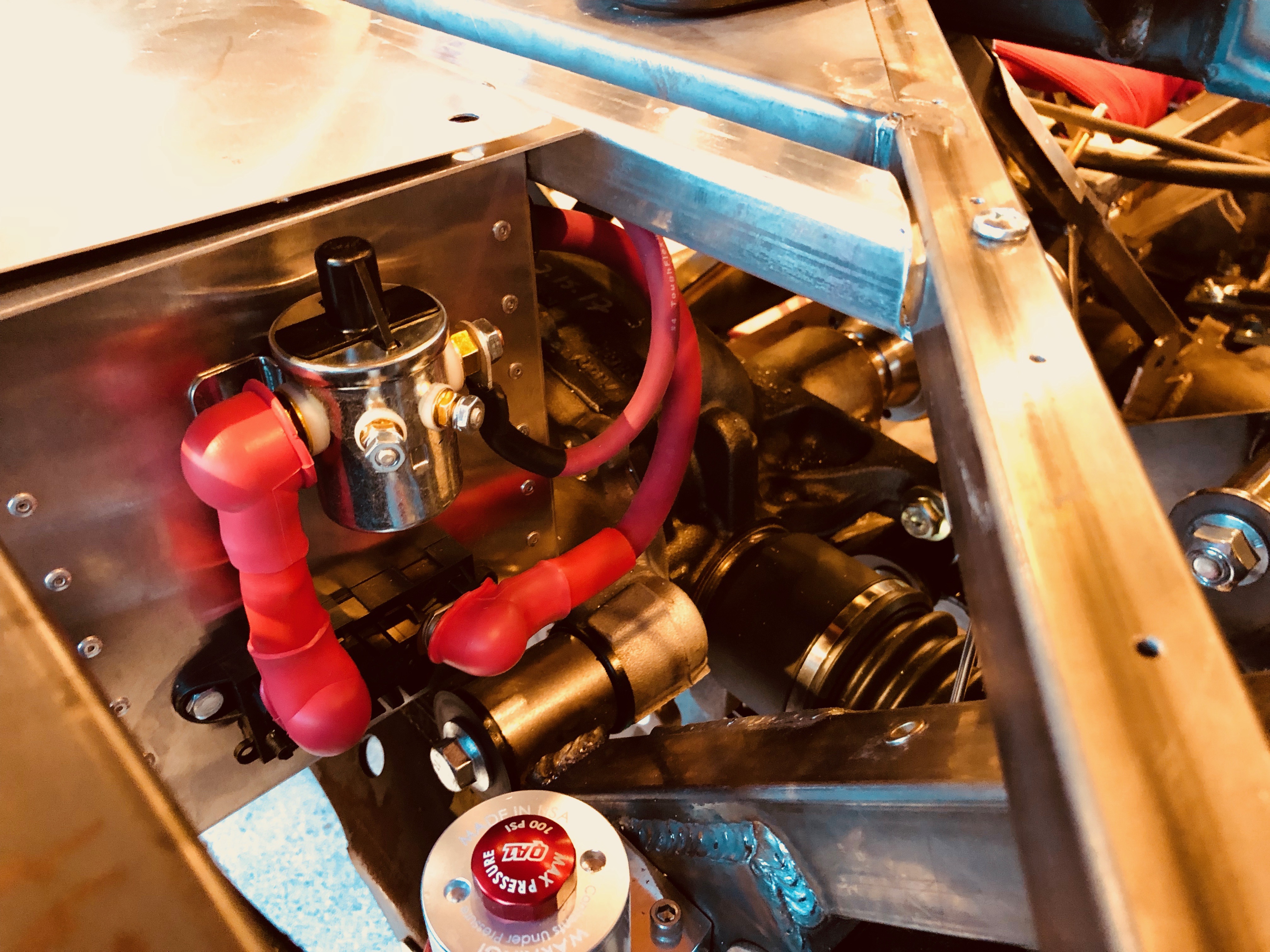
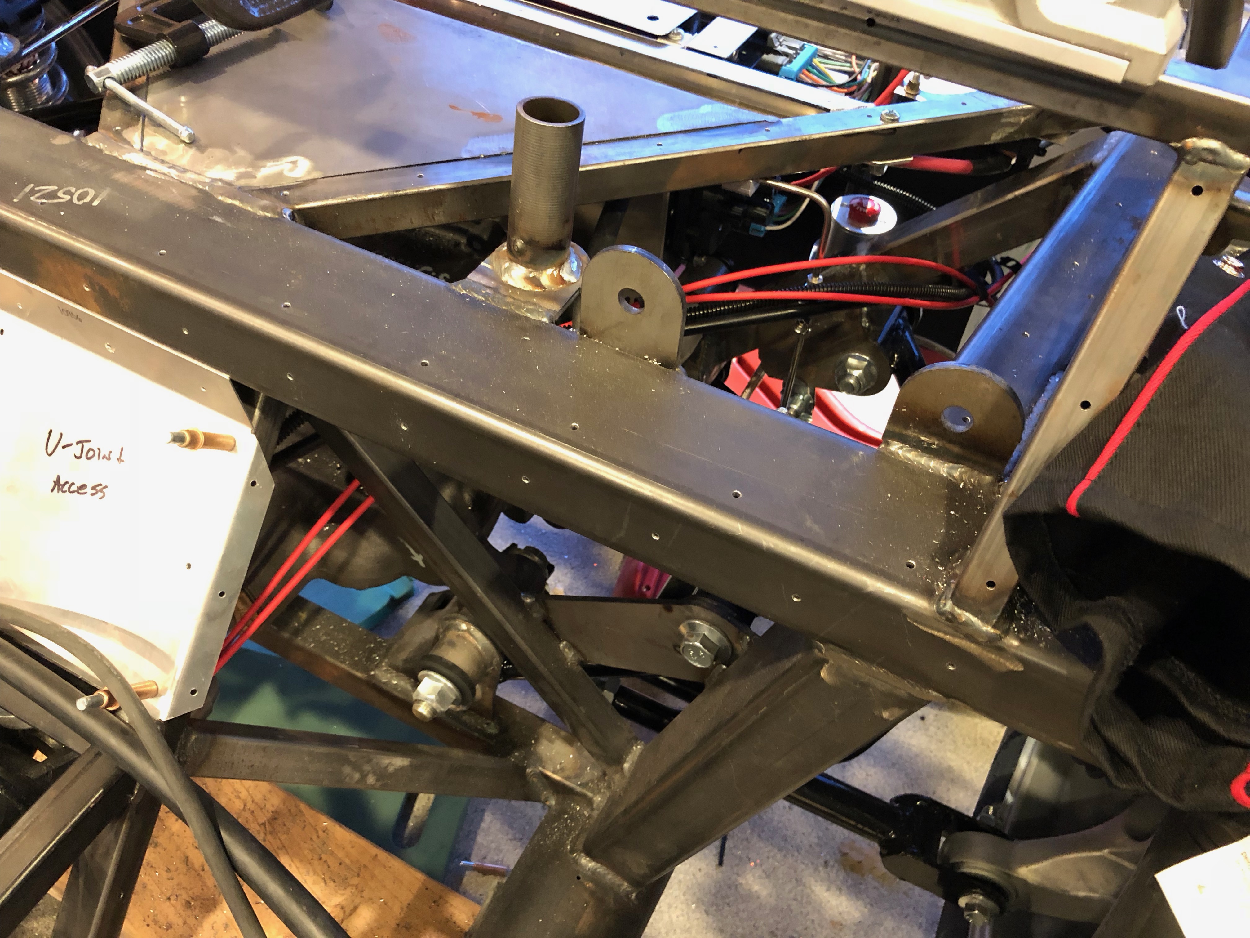
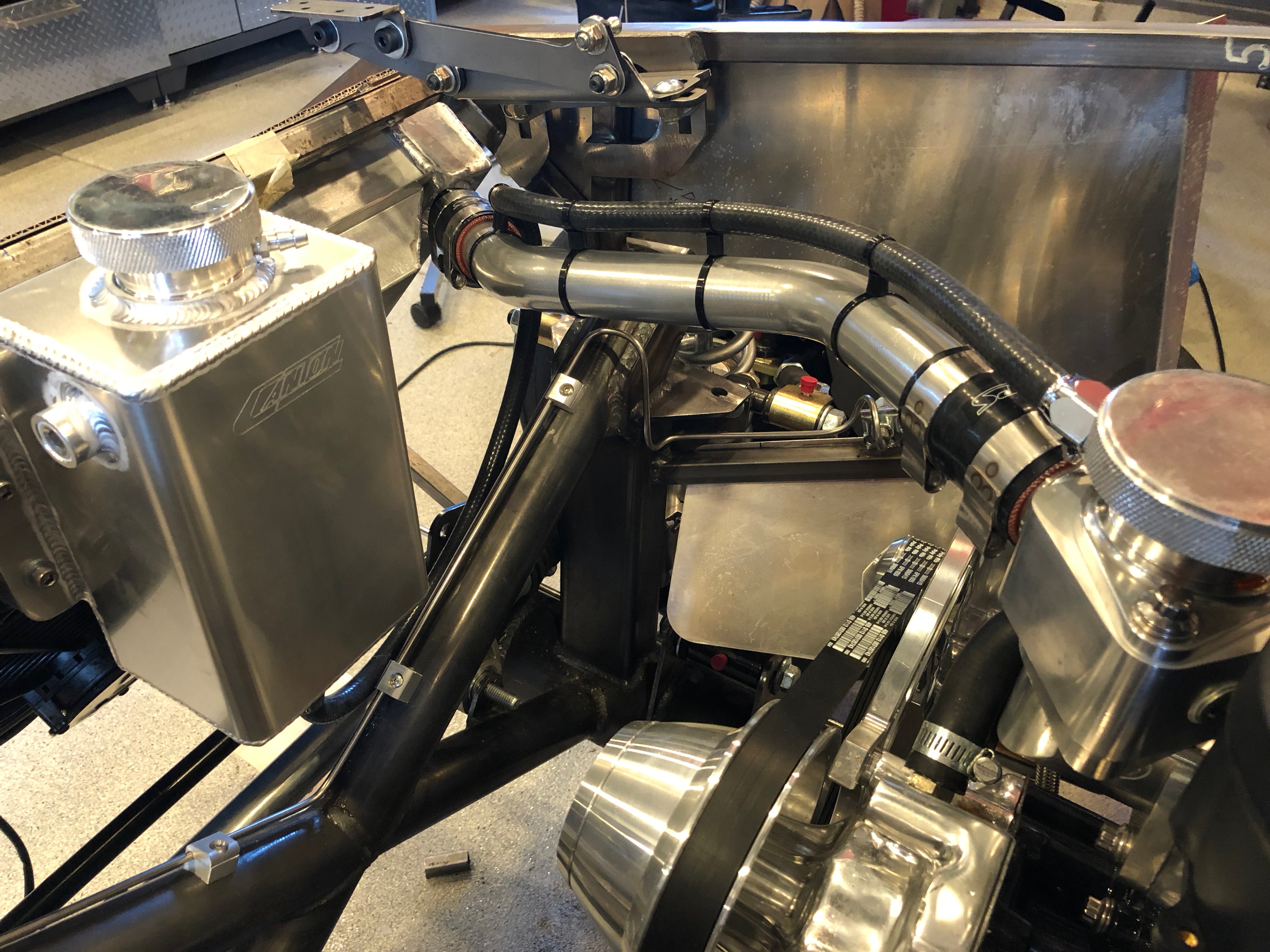
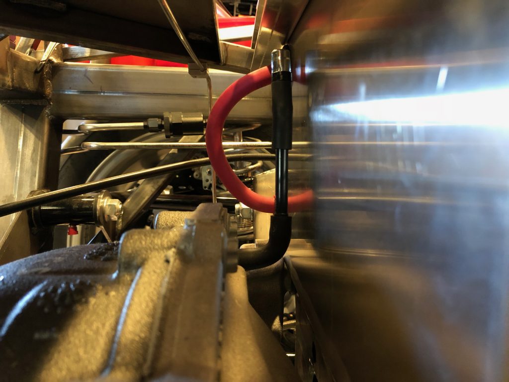
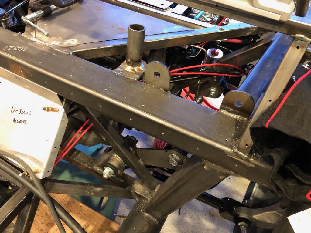
The power wire connects to the front of the buss bar (at the top of this picture). This is looking up from below.
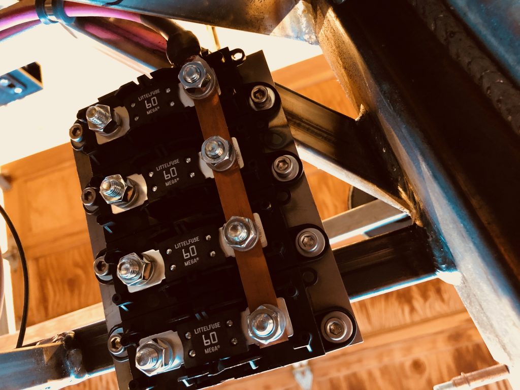
The wire is secured with an adel clamp just in front of the mega fuses and then follows the forward battery box support to the right side of the battery box.
There, it drops down and hooks to the right side of the inRESERVE solenoid.
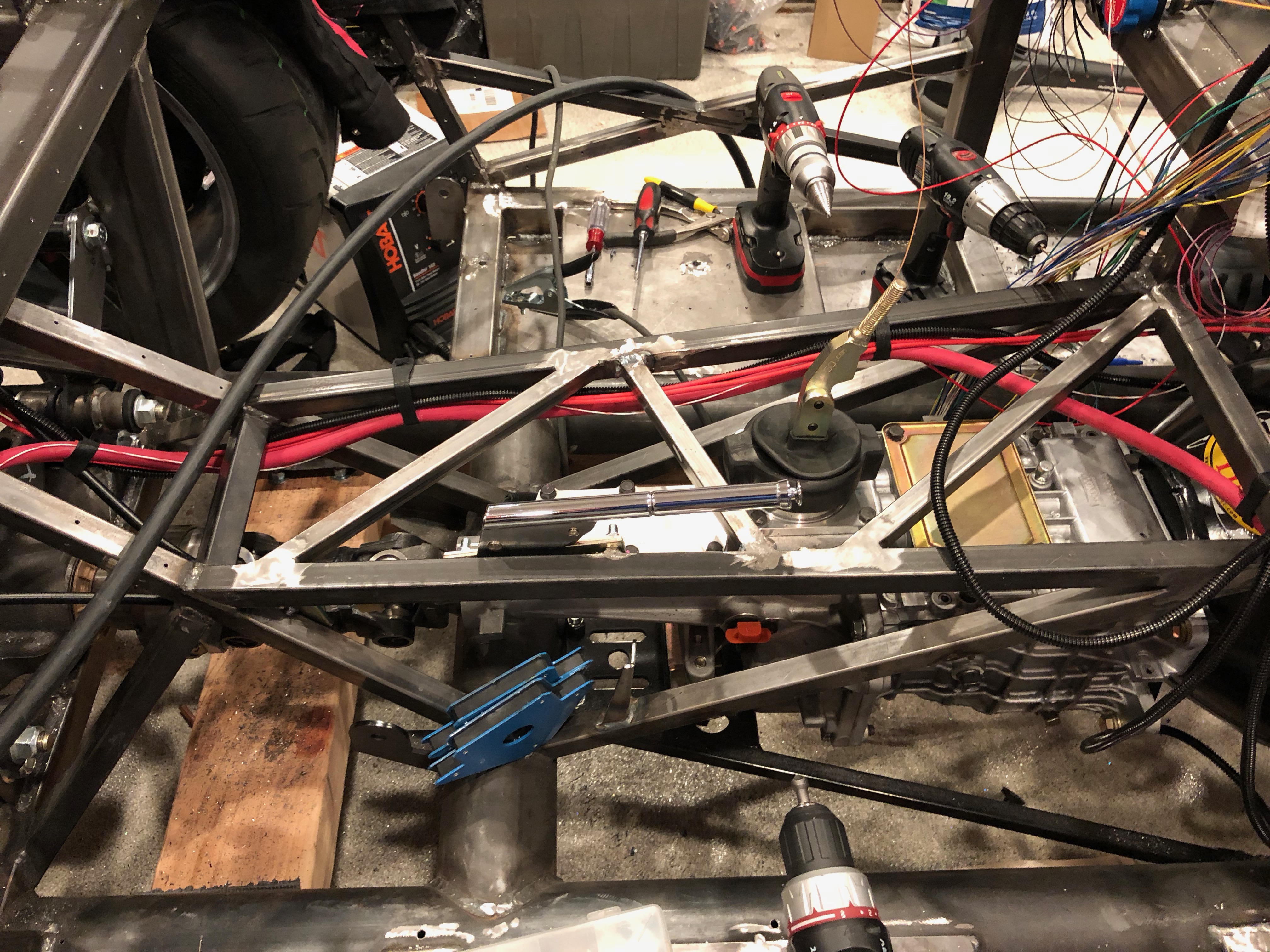
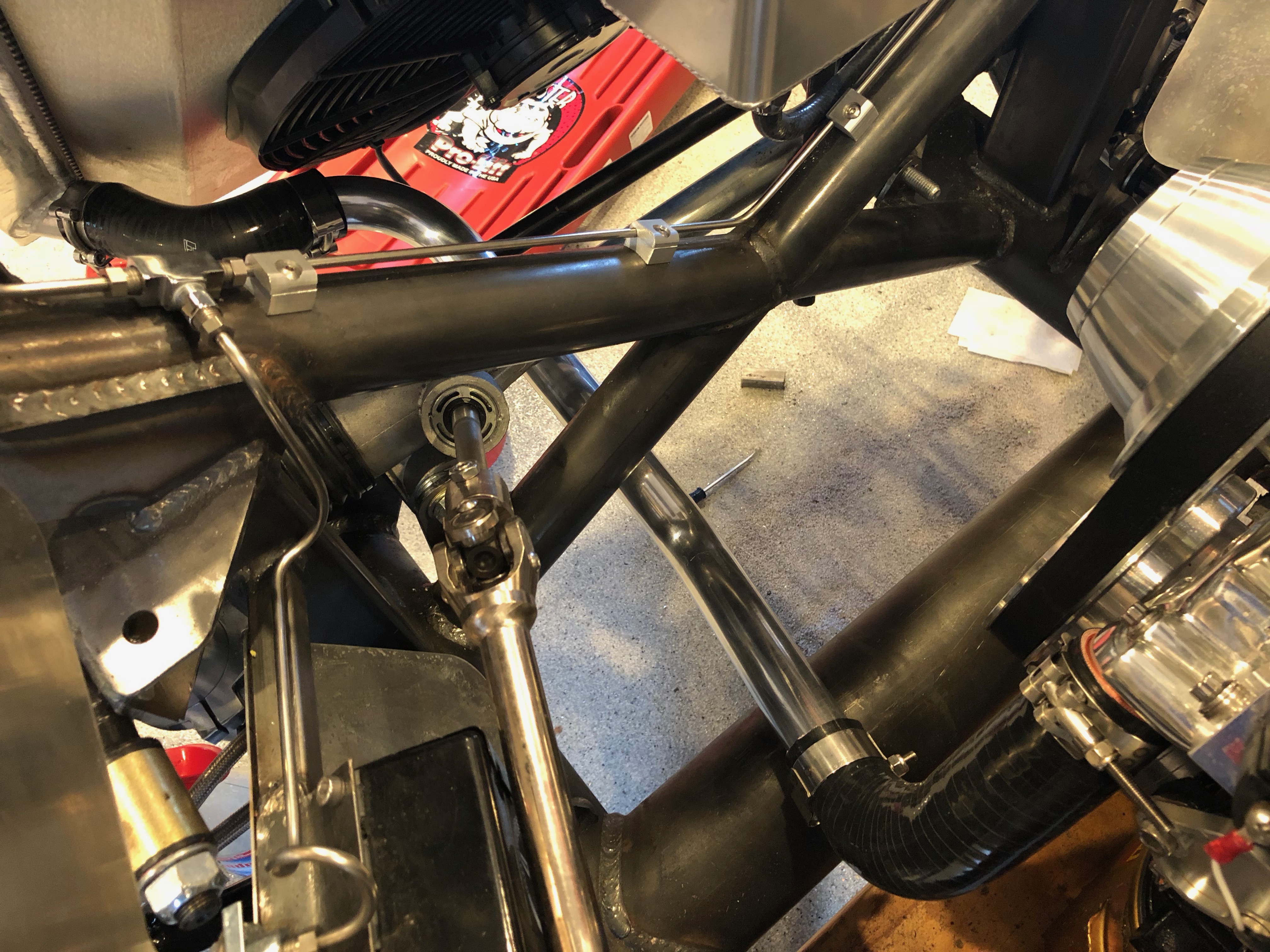
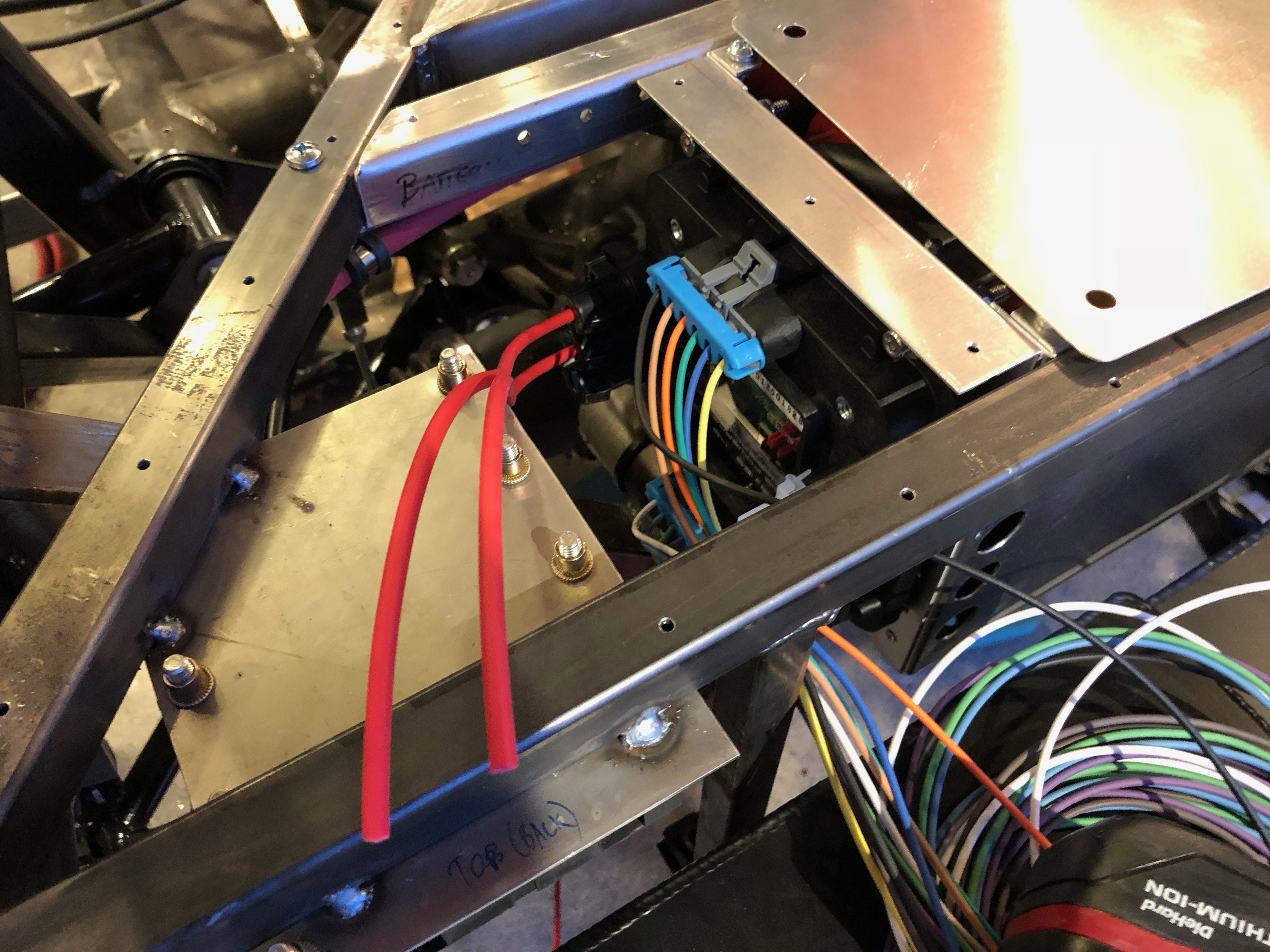
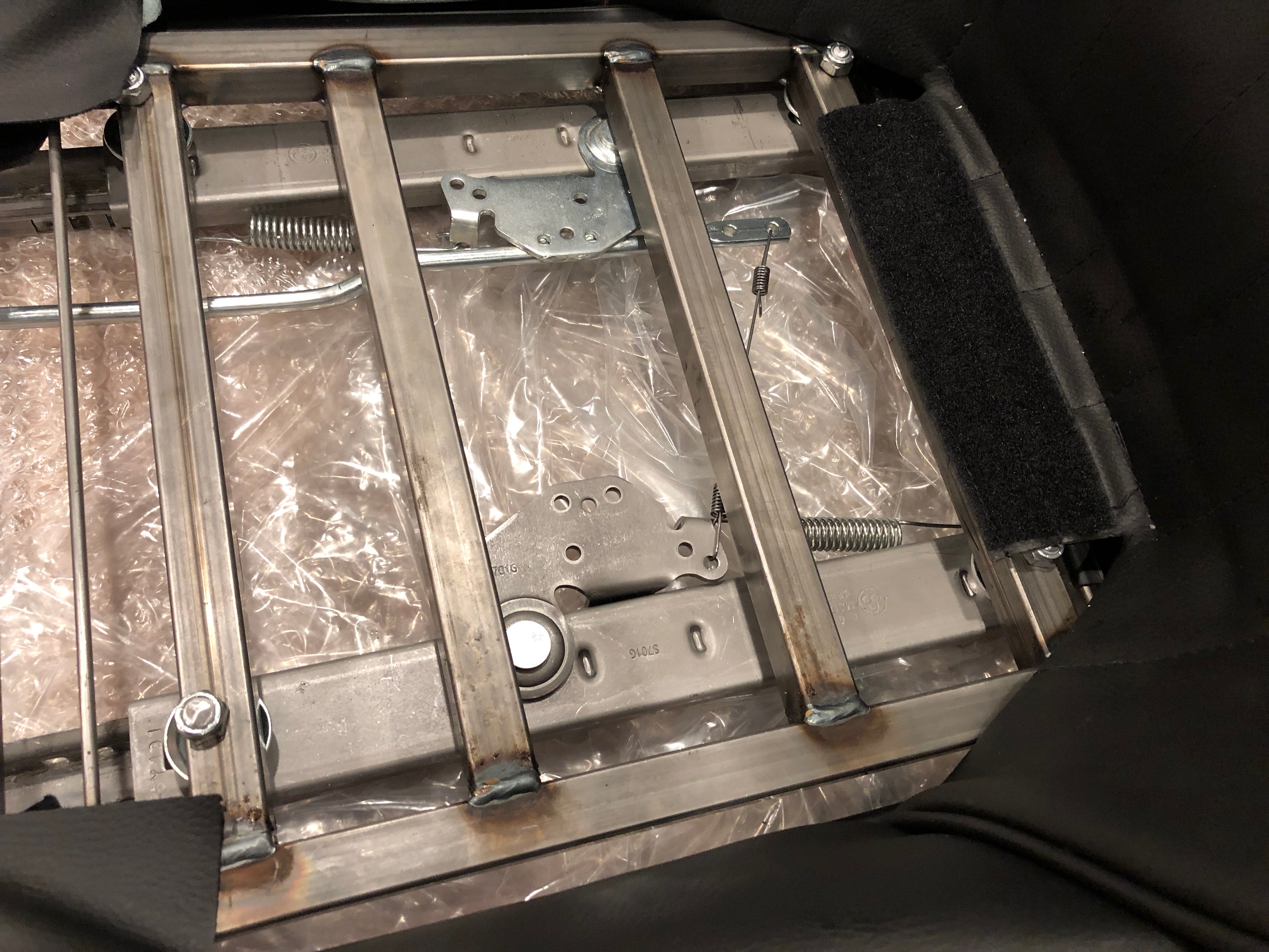
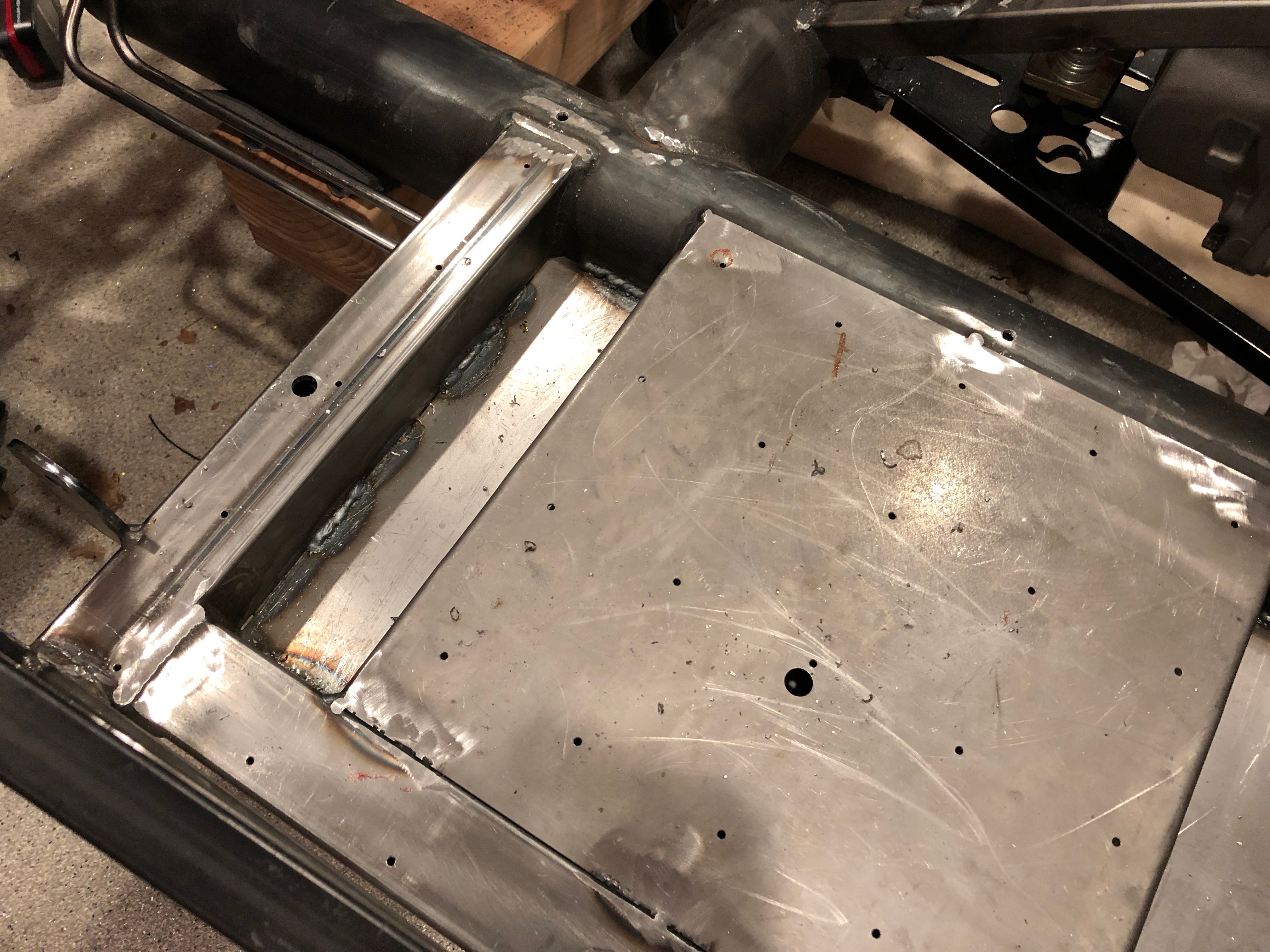
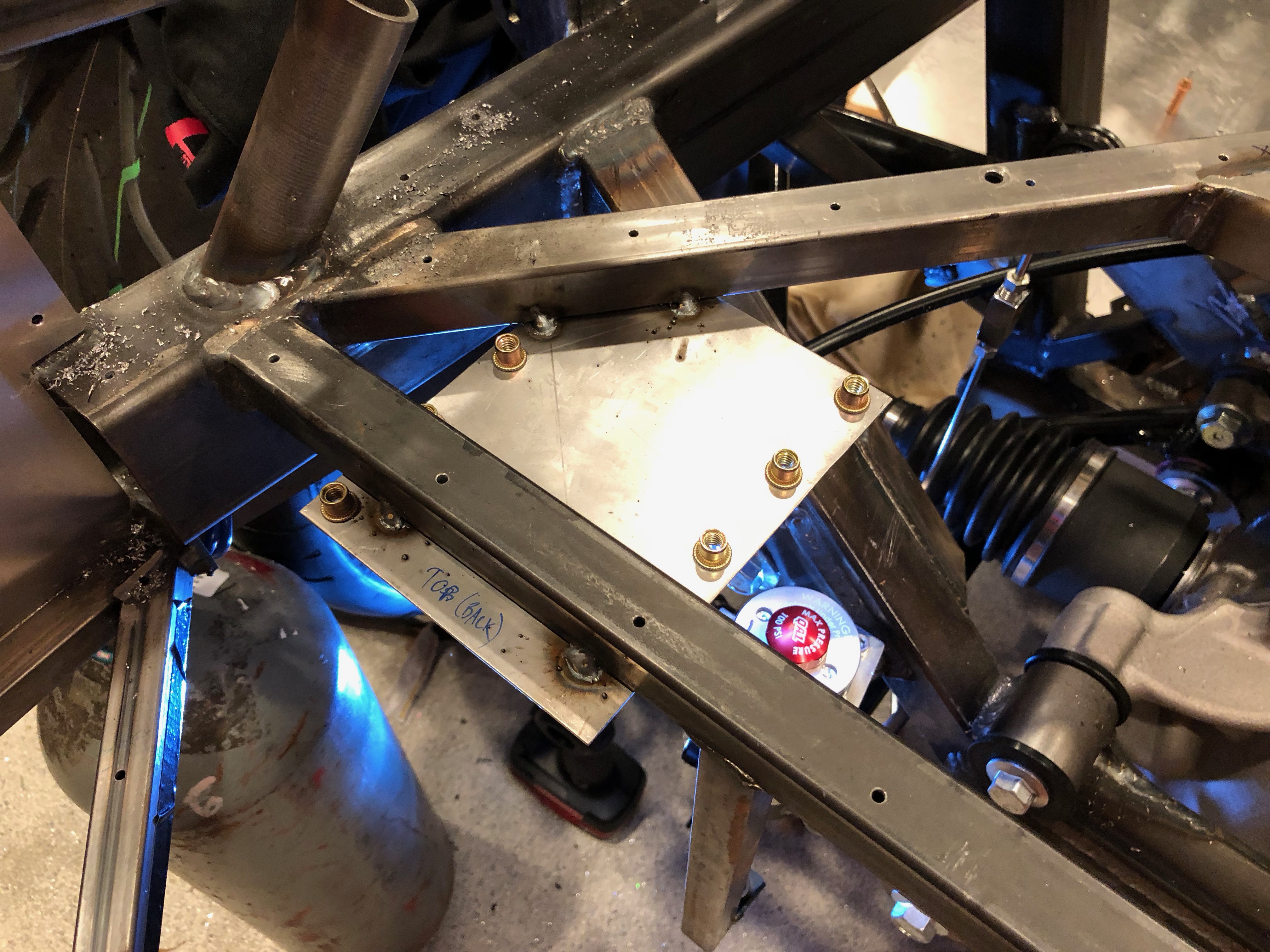
I installed the power wires in the rear load cell that will connect to the mega fuses. I left them a little long for right now until I have a better idea where all the wires will route in this area.
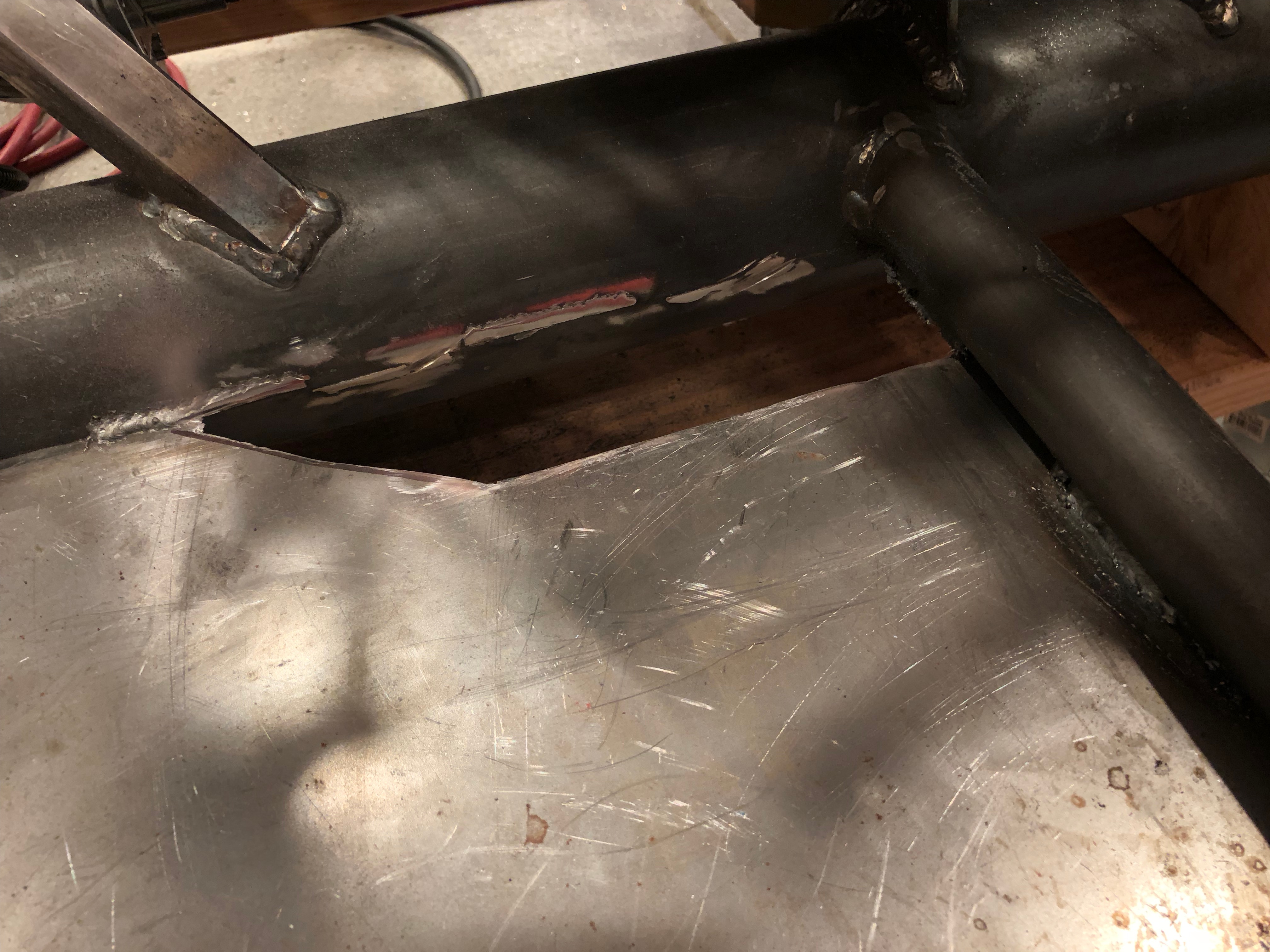
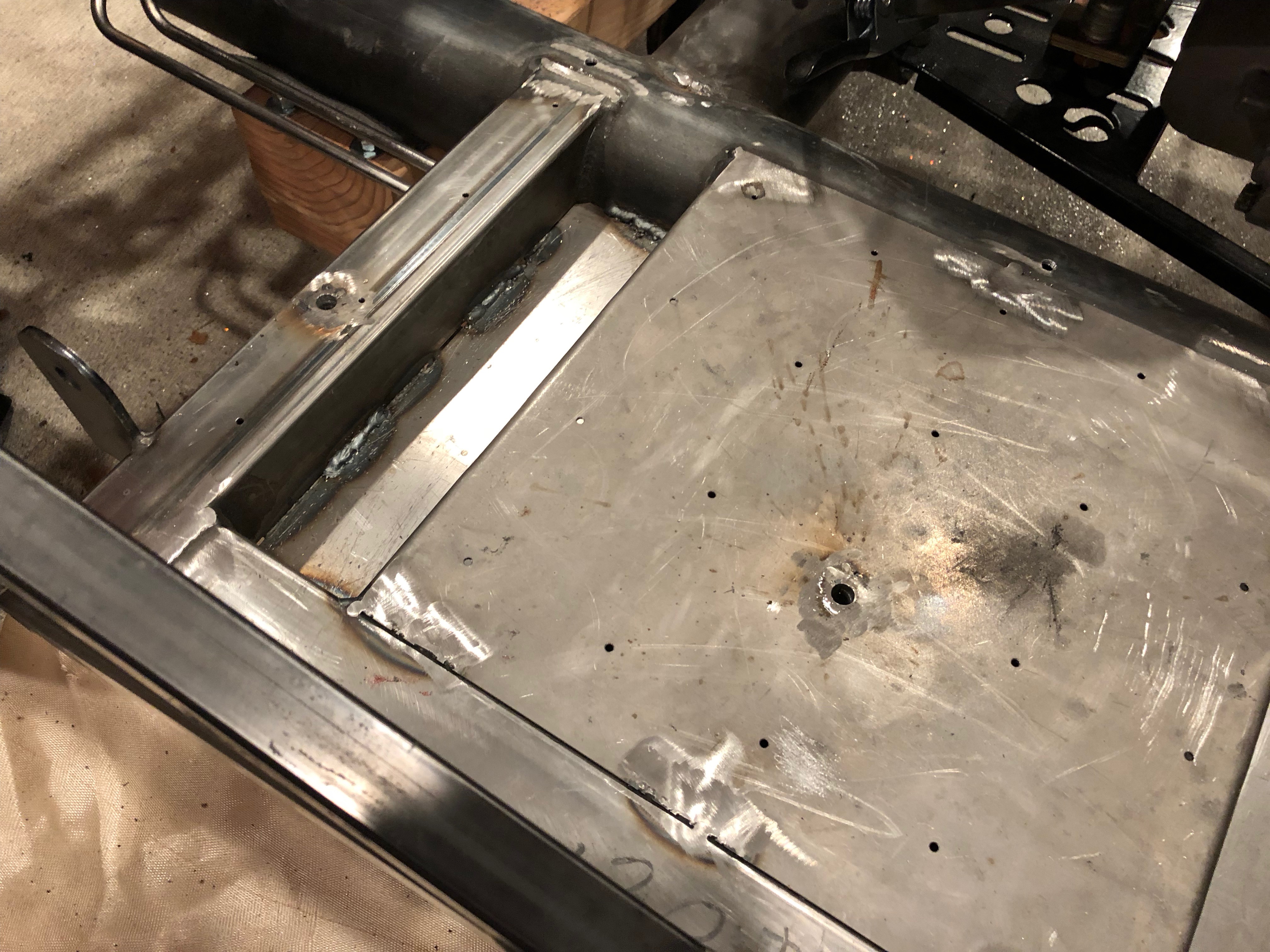
I also installed the power wires in the front load cell and snaked them down through the transmission tunnel.
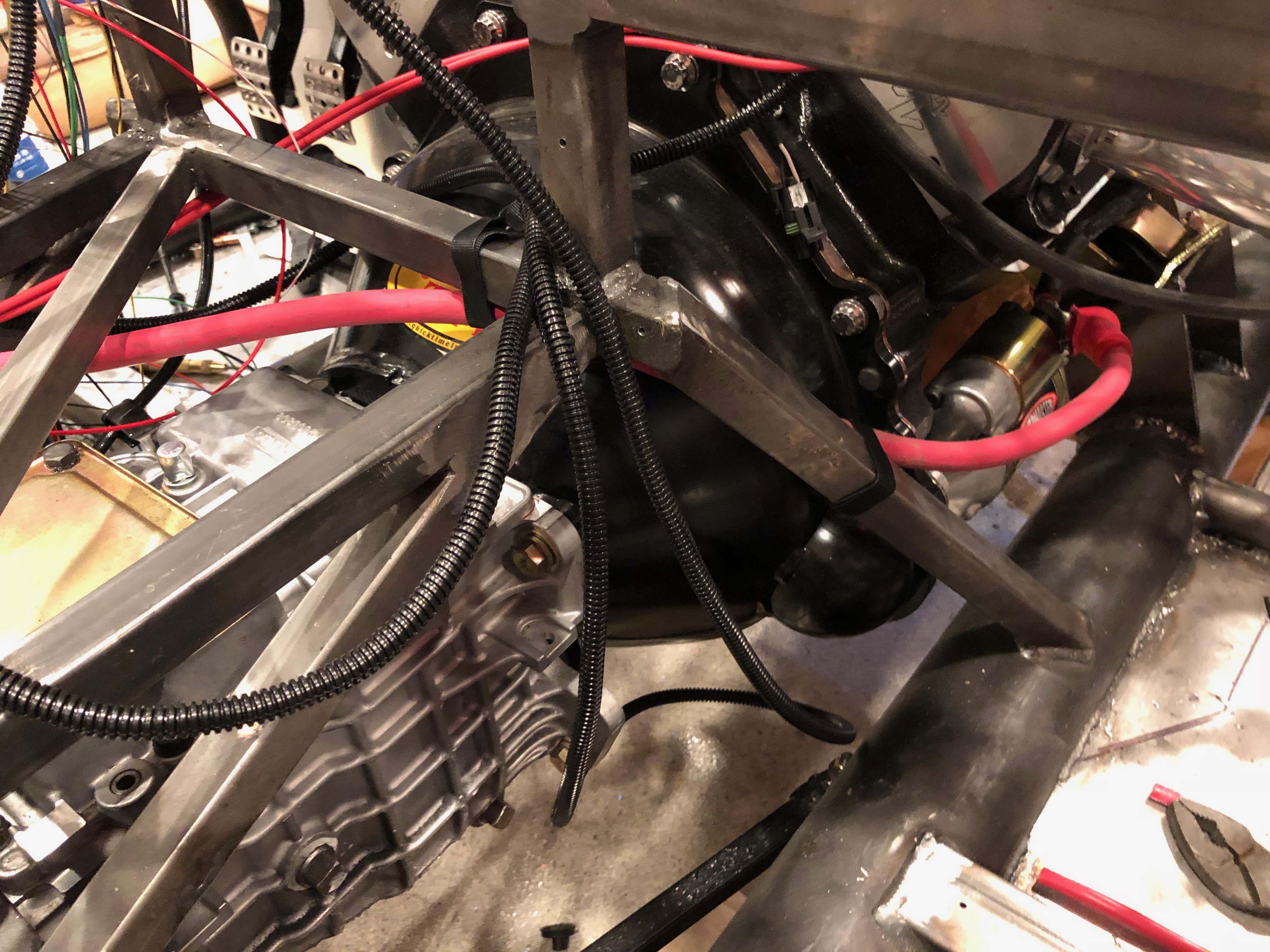
The run along the upper left side of the transmission tunnel…
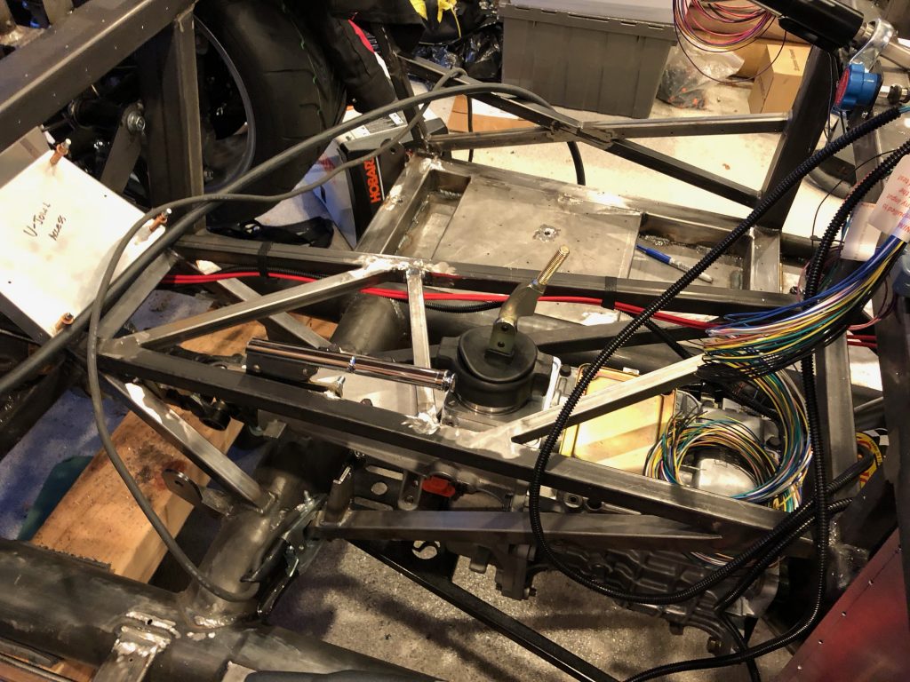
…where they follow the left parking brake cable back to the mega fuses. These are also left long for now.
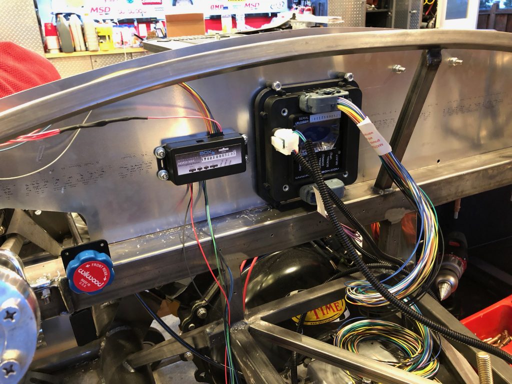
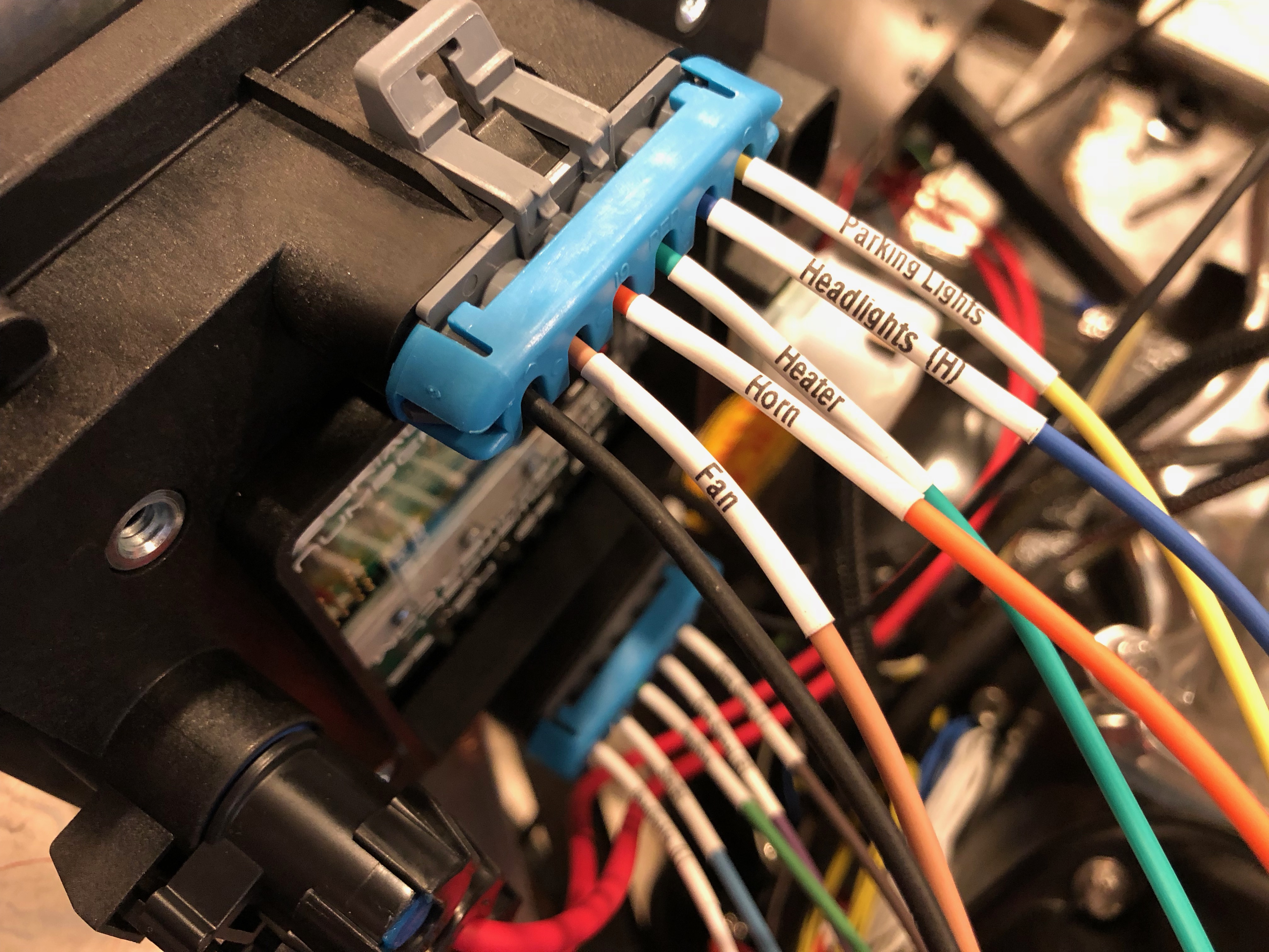
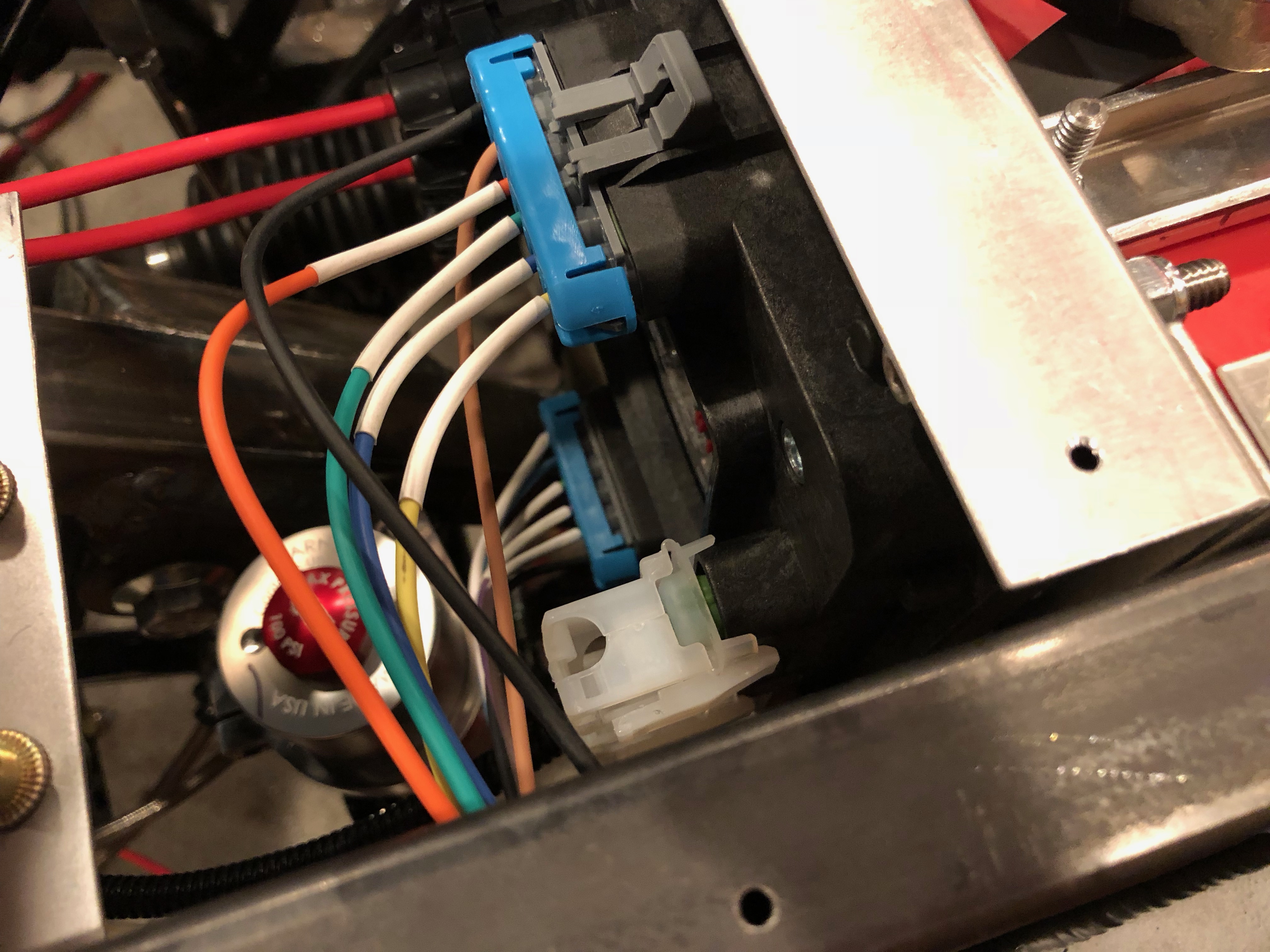
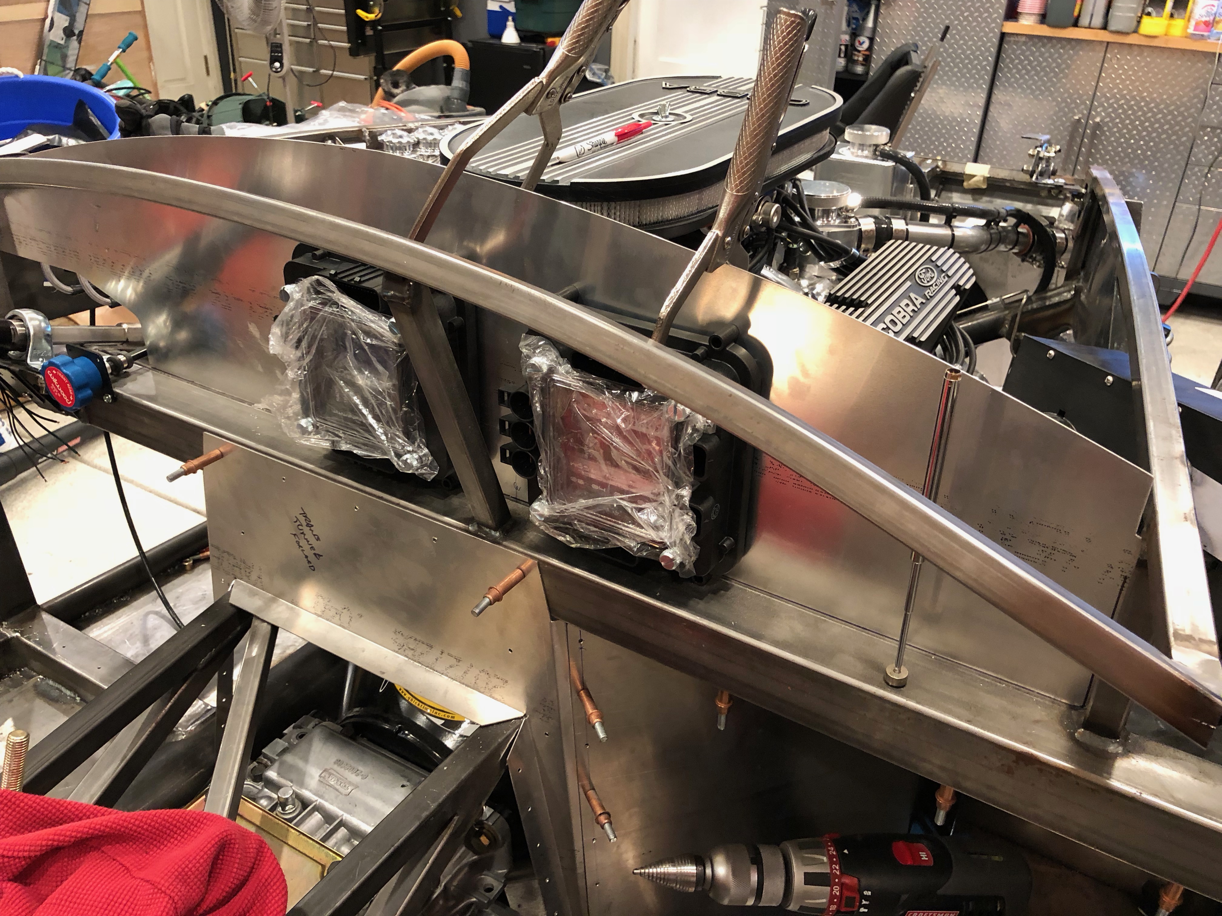
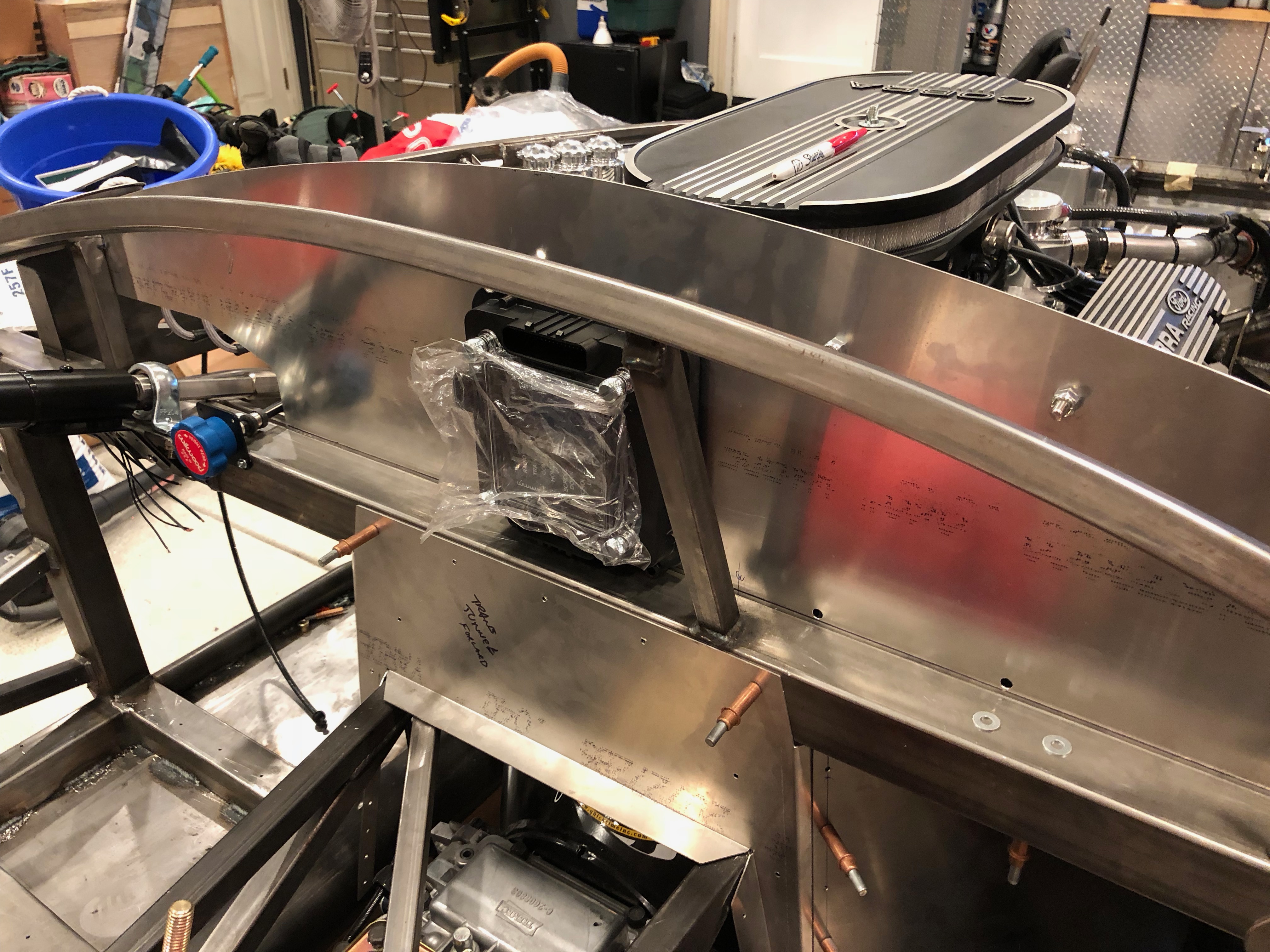
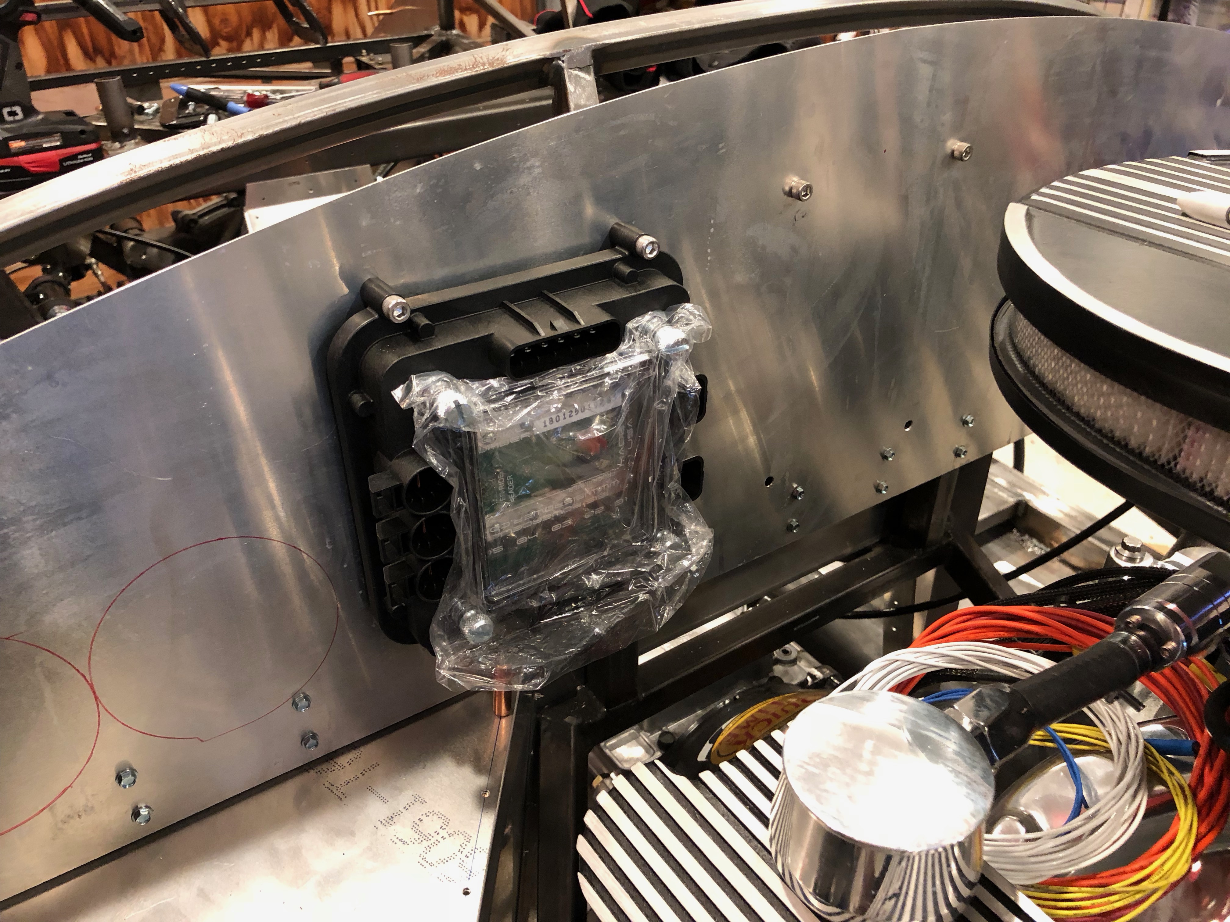
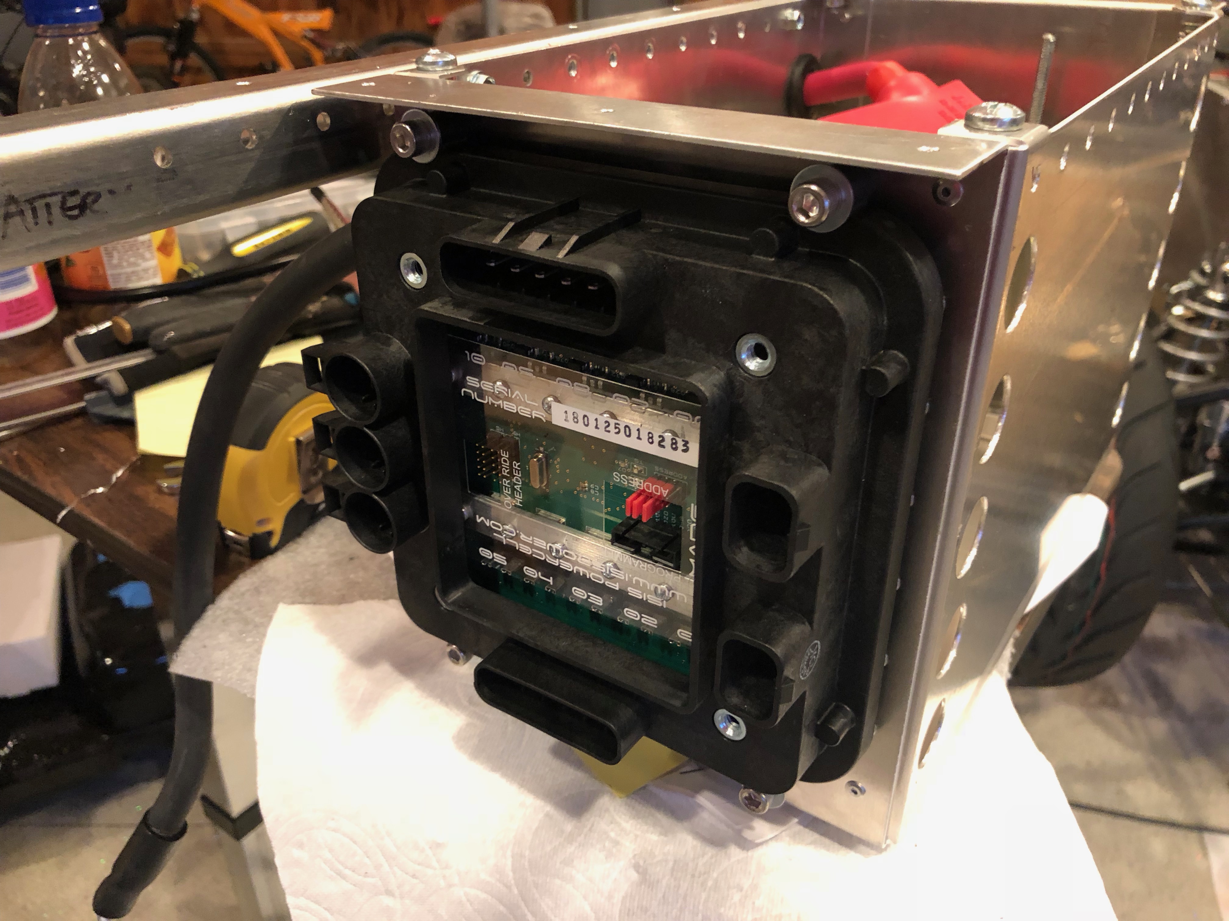
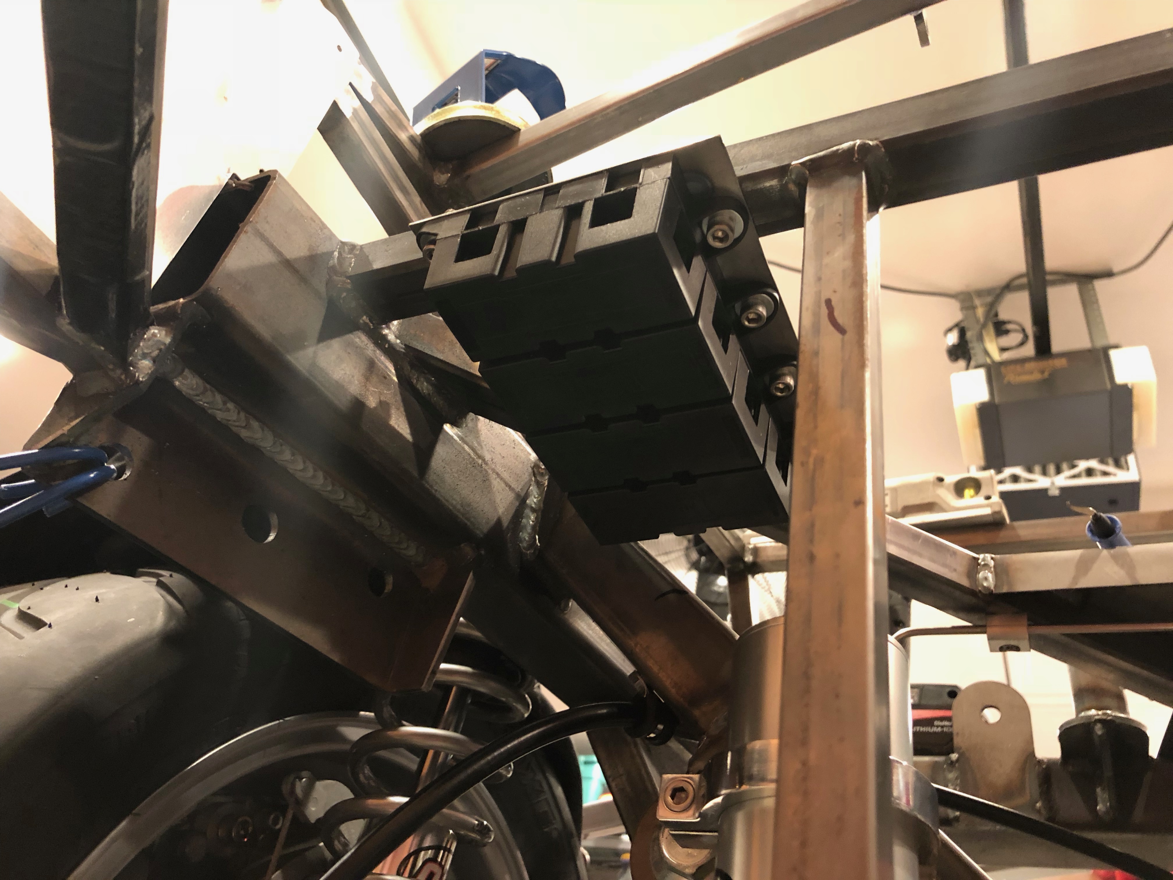
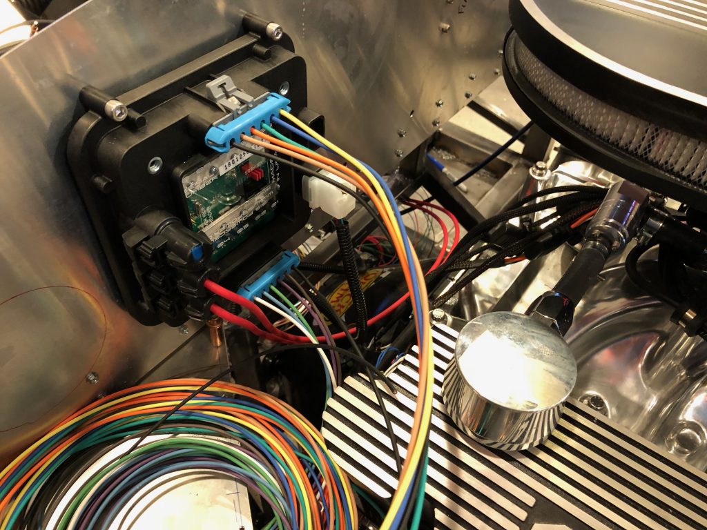
Jenn then installed the inDASH MAX box on the aft side of the firewall.
It’s installed just to the left of the mastercell.
Finished Passenger Seat and Electrical System Components
I wrapped up the passenger seat by trimming the bolts and installing the wire that connects the mechanisms on the two tracks.
I then cut some pieces of 1/2″ steel tubing and welded them into the chassis then ground them flat.
I finally determined the location for the master cell (left) and front load cell (right). The load cell will actually install on the other side of the firewall, but I’m drilling it on this side because I don’t have drill access on the other side.
After deburring the holes, I temporarily bolted the mastercell to the aft side of the firewall.
The front load cell is mounted on the right side of the firewall. This should keep it clear of the throttle mechanism on the left side and allow easy access if I ever need to access it.
I’ve been playing with the location of the heater assembly. This is quite a bit bigger than the one Factory Five sells, so it can’t install on the firewall. I think I’m going to end up installing it at an angle as shown and then run a pair of 3″ diameter pieces of ducting from the heater to the firewall. A plenum on the other side will distribute the air to the foot boxes and defroster vents.
The ducting will connect to the plenum through this pair of 3″ diameter holes. There will be flanges installed to the firewall here.
Coolant Reservoir Overflow and Passenger Seat
I ran a piece of silicone tubing from the coolant reservoir overflow down to the bottom of the chassis. This is probably only temporary, but I need to have something in place before we fill the coolant system.
Next, I resumed installing the passenger seat. I bolted the seat tracks to the bottom of the seat and then installed the bolts that attach the inner track to the floor. I then drilled the forward hole in the outer track, dropped in a bolt to lock the track in place, slid the seat forward and marked for the rear hole.
After removing the seat, I drilled the final hole in the floor.
Finally, I removed the seat pans and enlarged the holes to 1/2″ in preparation for welding in the spacers. It’s too loud to run the grinder tonight, so I’ll do this tomorrow.
Started Installing Passenger Seat Track
Coolant Reservoir Plumbing and Began Electrical System
I routed the silicone tubing from the water neck to the bottom of the coolant reservoir. I used some zip ties and plastic tubing to secure it to the upper radiator tubing. I’m not sure I like this method of securing the tubing, but it will do for now.
After a two month wait, we finally got our electrical system from InfinityBox. We ordered the two-cell system which includes a master cell under the dash and two load cells, one for the front of the car and one for the rear. There’s plenty of room under the hood for the front cell, but there’s really very little room in the rear of the car. The trunk has two levels: Under the rear (lower) level resides the fuel tank. Under the forward (upper) level resides the differential, driveshafts, suspension (including remote reservoirs), parking brake cables, rigid brake lines, battery, inReserve system, rear load cell and mega fuses. The other consideration is that all of this needs to maintained from below once the car is assembled. Although there is plenty of volume above the differential, it’s virtually impossible to reach from below. All of the electrical components really need to be installed between the differential and the fuel tank. The battery takes up the bulk of that space, the but the side of the battery box is a pretty convenient spot to mount components.
The right side of the battery box has the inReserve system and primary mega-fuse, but the left side of the box is a perfect place for the rear load cell. This keeps it well protected, but easy to access from below. This is currently attached with bolts and nuts, but I’ll replace the nuts with nutplates to make this easy to remove from below in case I ever have to do so.
The InfinityBox instructions recommend that the primary power wire from the battery to the mega fuses be as short as possible. That means that these need to be installed in the rear of the car as well. I spent some time playing with various mounting locations and settled on installing them high on the left side of the car. I fabricated a small steel plate and welded it to the chassis and installed 8 riv-nuts.
The mega fuses install from below so that they can be accessed in the future if necessary. This will hang over the top of the fuel tank slightly, but there should be plenty of vertical clearance to access these with the tank in place.