Prepped Engine to Run

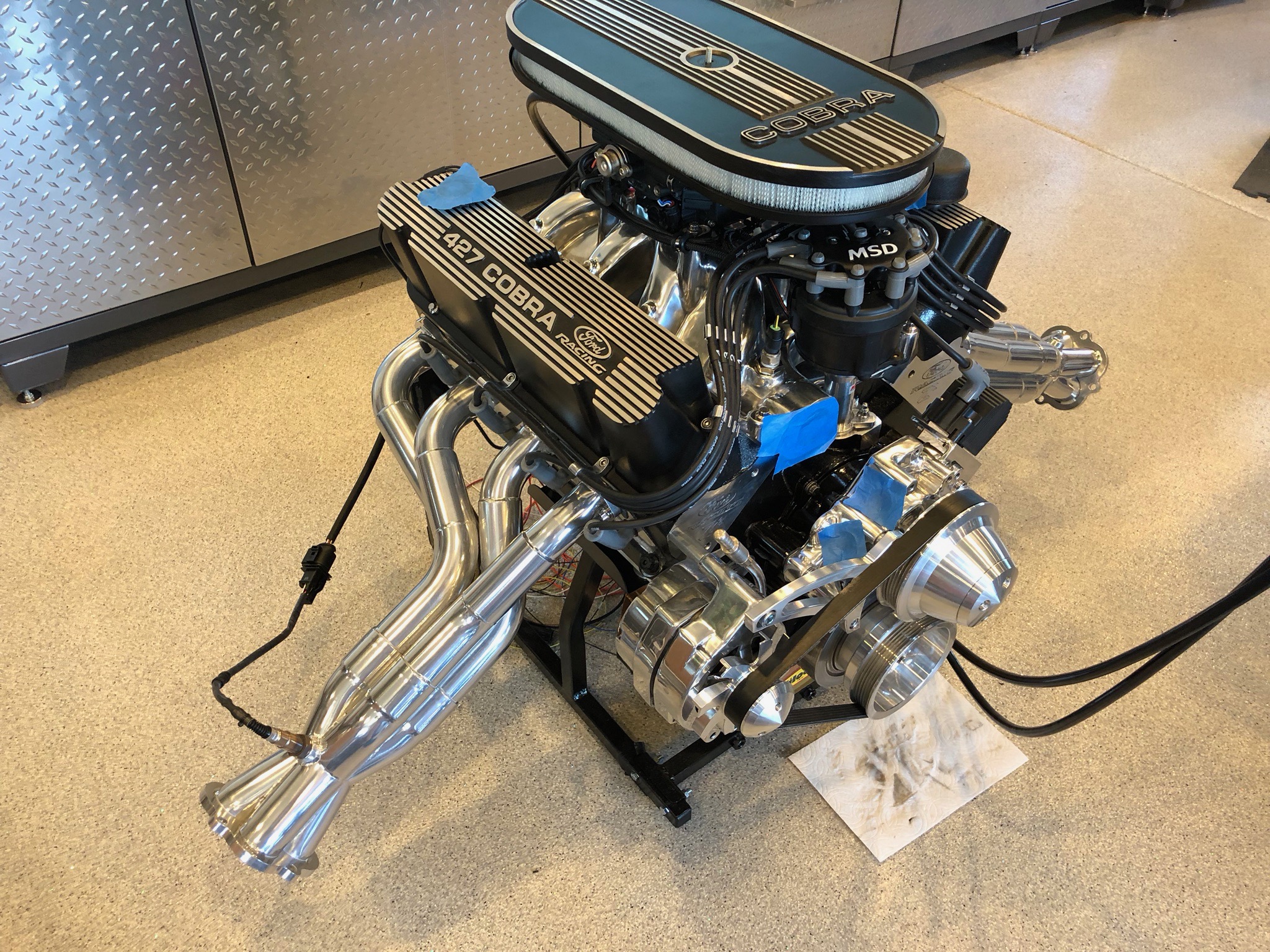
We have a Halloween Party at our house every year, and it’s coming up in less than two weeks. I decided it would be fun to be able to fire up the engine at the party because I’m sure many people will be interested in the party. To that end, I’m going to hook everything back up as it was at the dyno shop along with the necessary additional bits to run the engine in the car (cooling system, starter, oil pressure and coolant temperature gauges, tachometer, etc.).

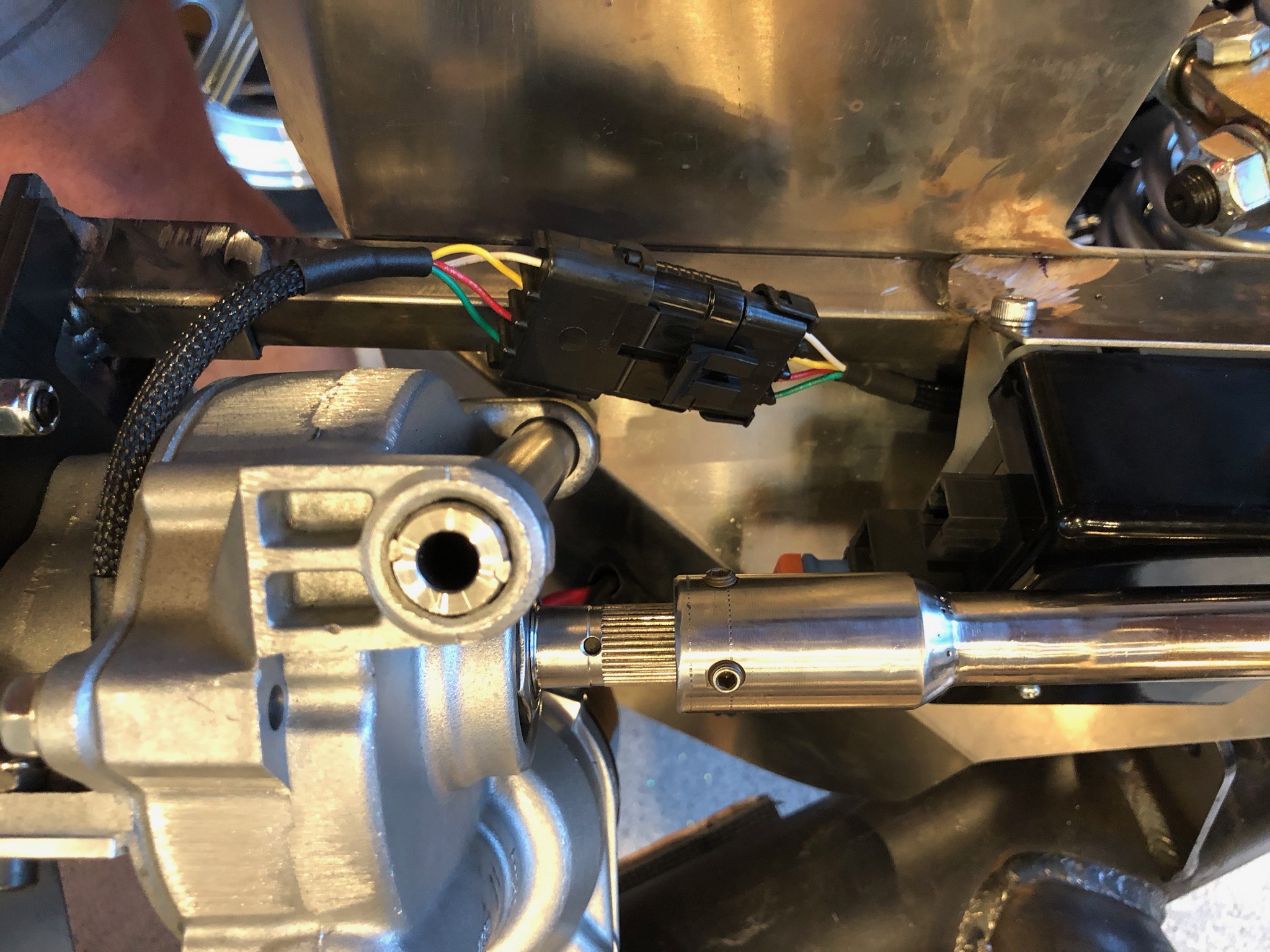
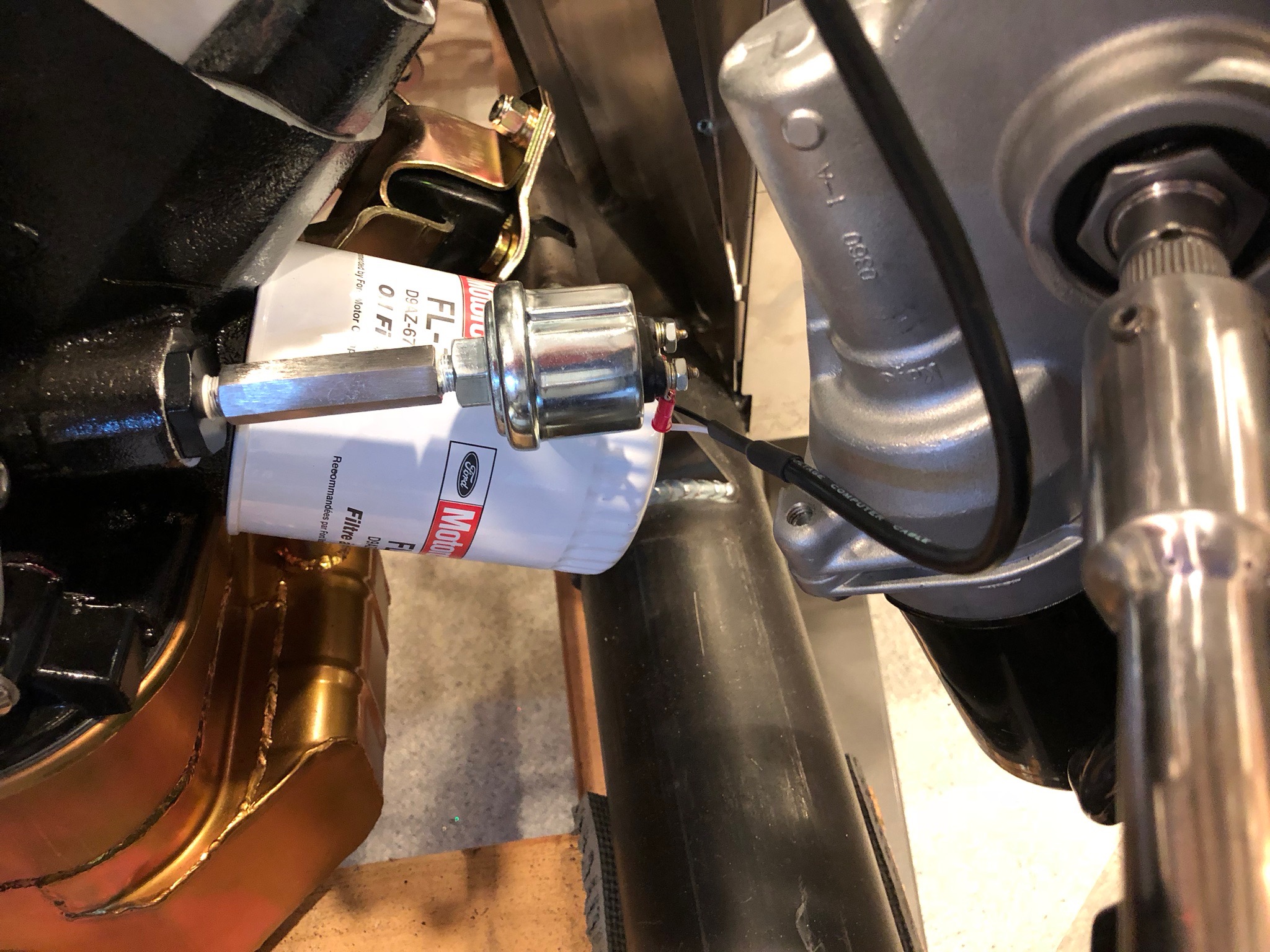
The dyno shop removed my oil pressure sender and hooked up their own hose to this extension. I reinstalled the sender and then hooked up a temporary pair of wires to drive the oil pressure gauge.

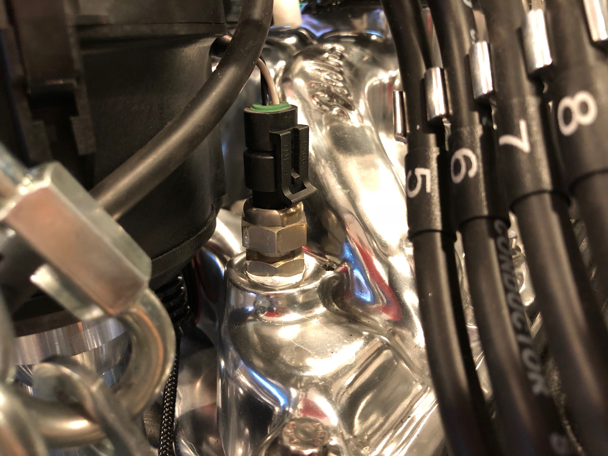
The dyno shop also installed their own coolant temperature sender, so I reinstalled my sender and hooked up the wires.

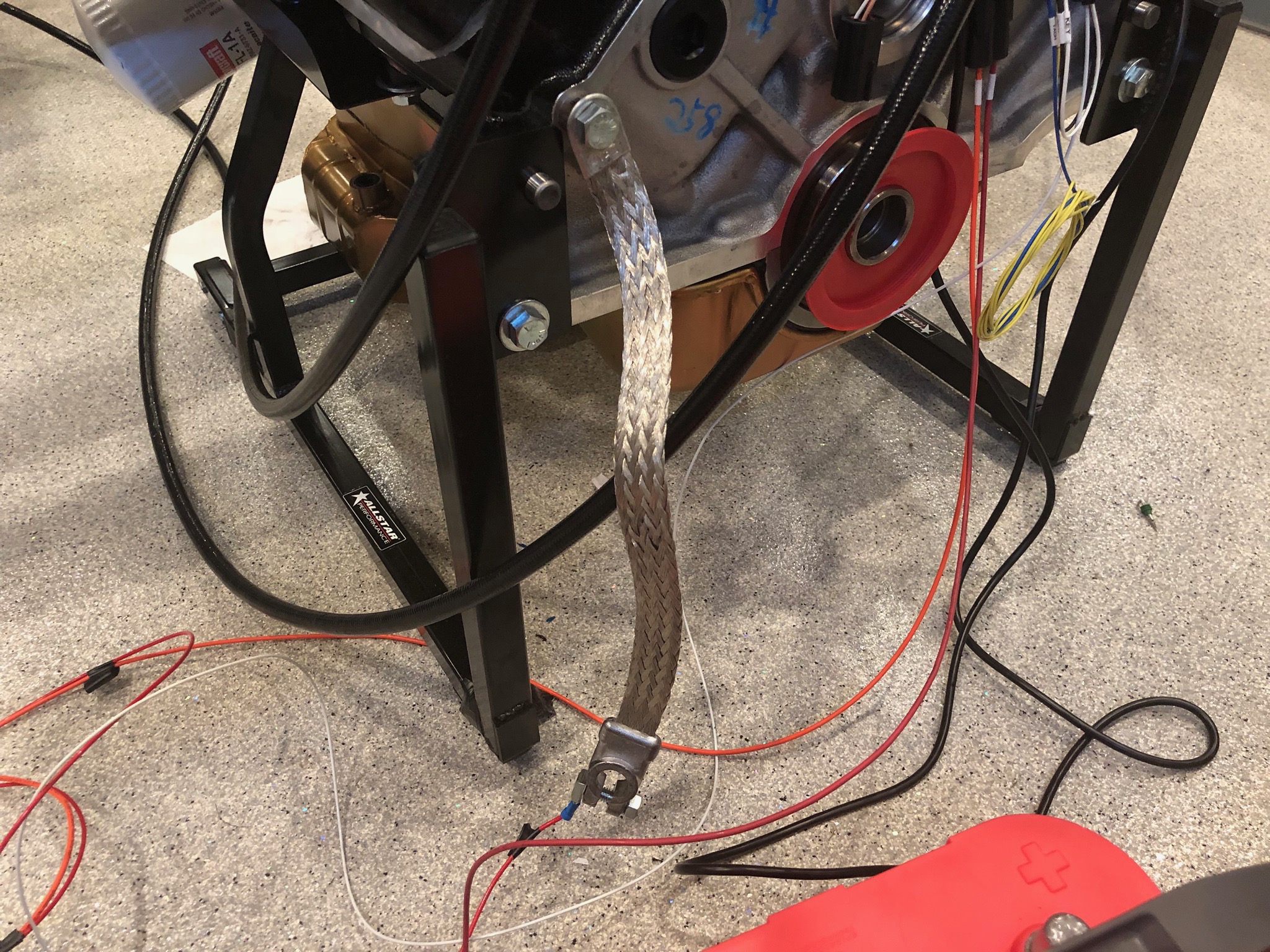
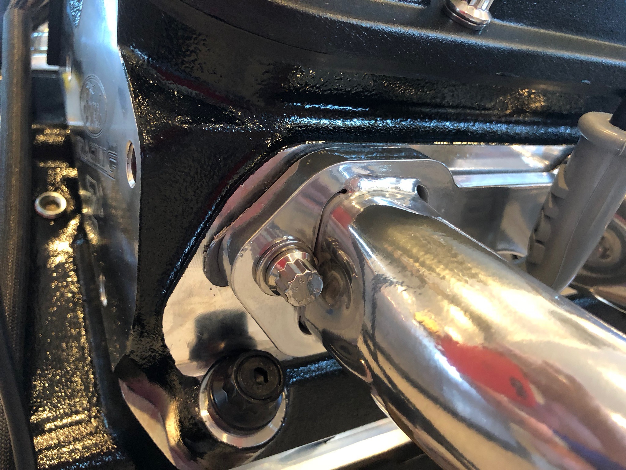
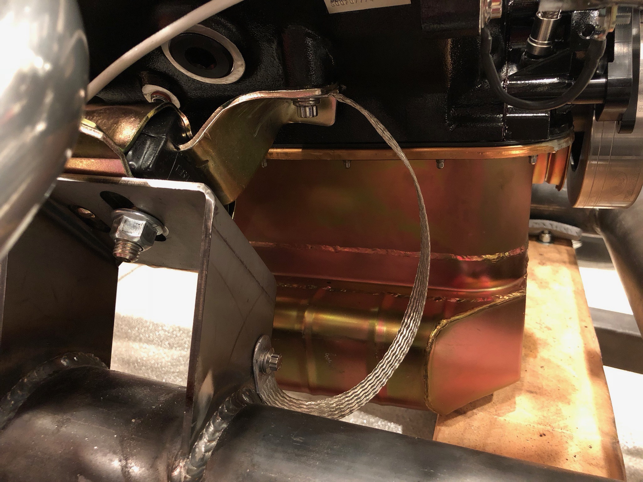
I also hooked up the engine ground strap from the right front engine mount bolts to the hole already provided in the mounting bracket.

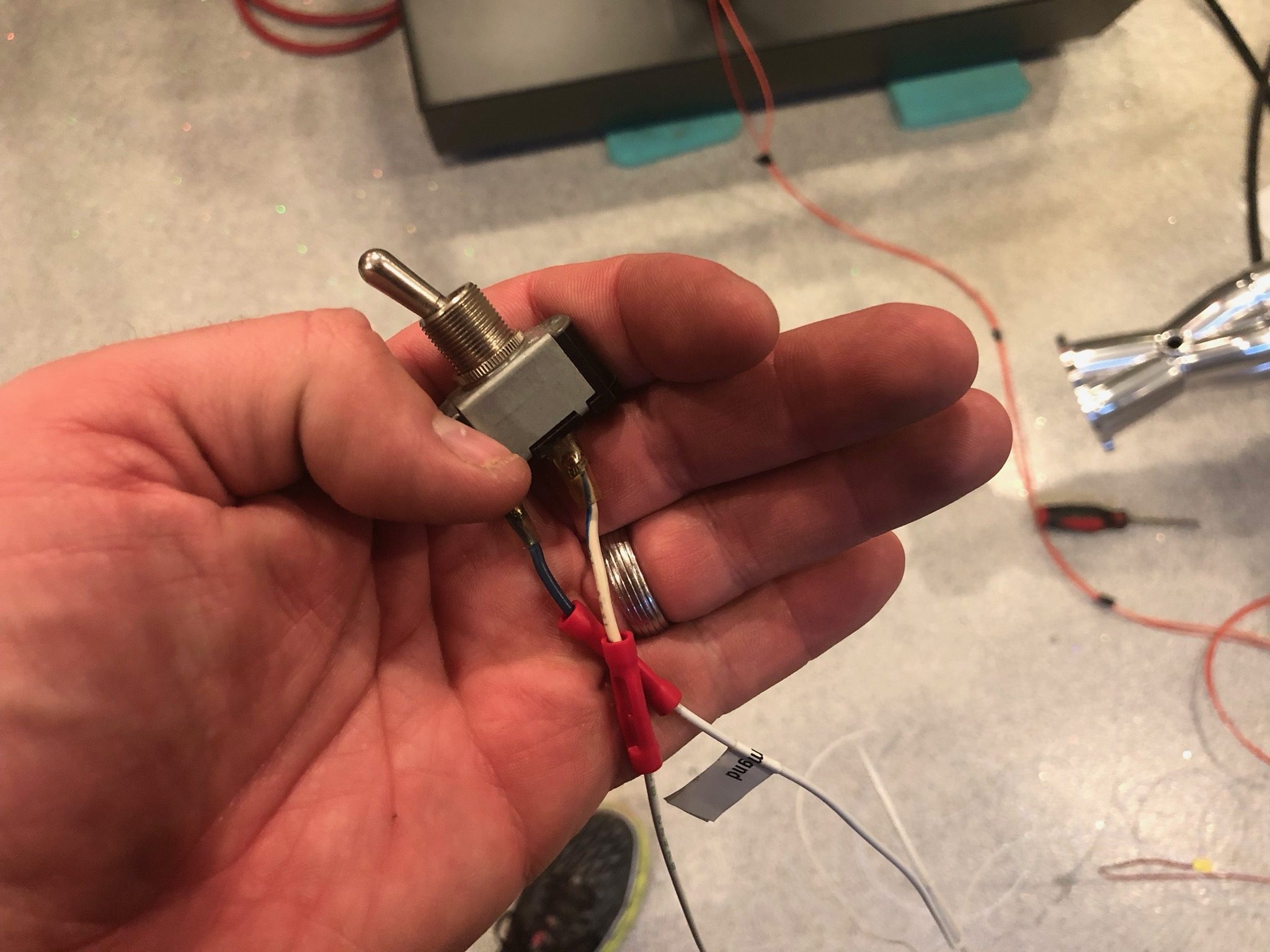
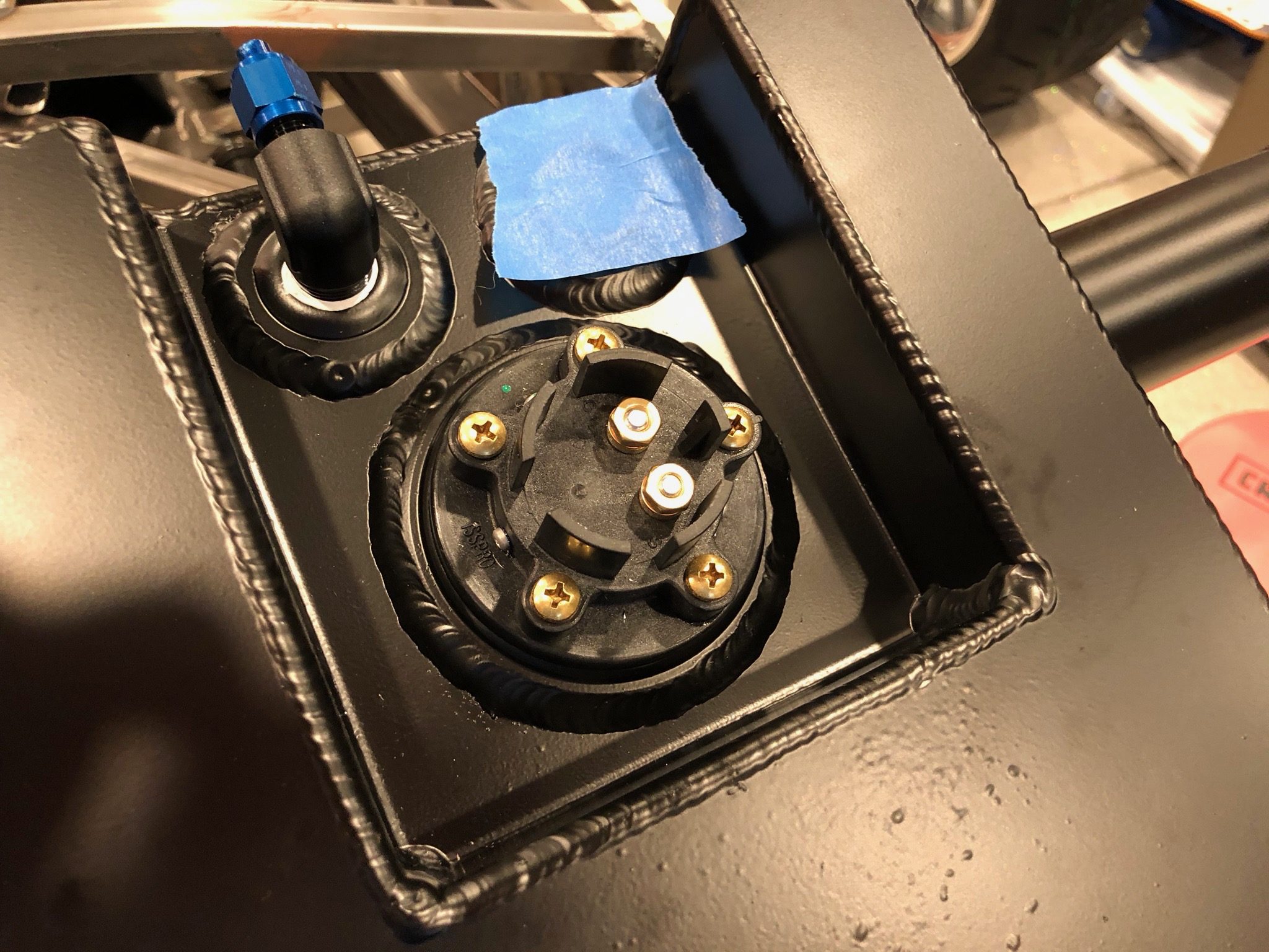
To be able to start the car, I used some scrap aluminum to temporarily hold the ignition switch. I still need to wire this, but there are only a few connections to make.

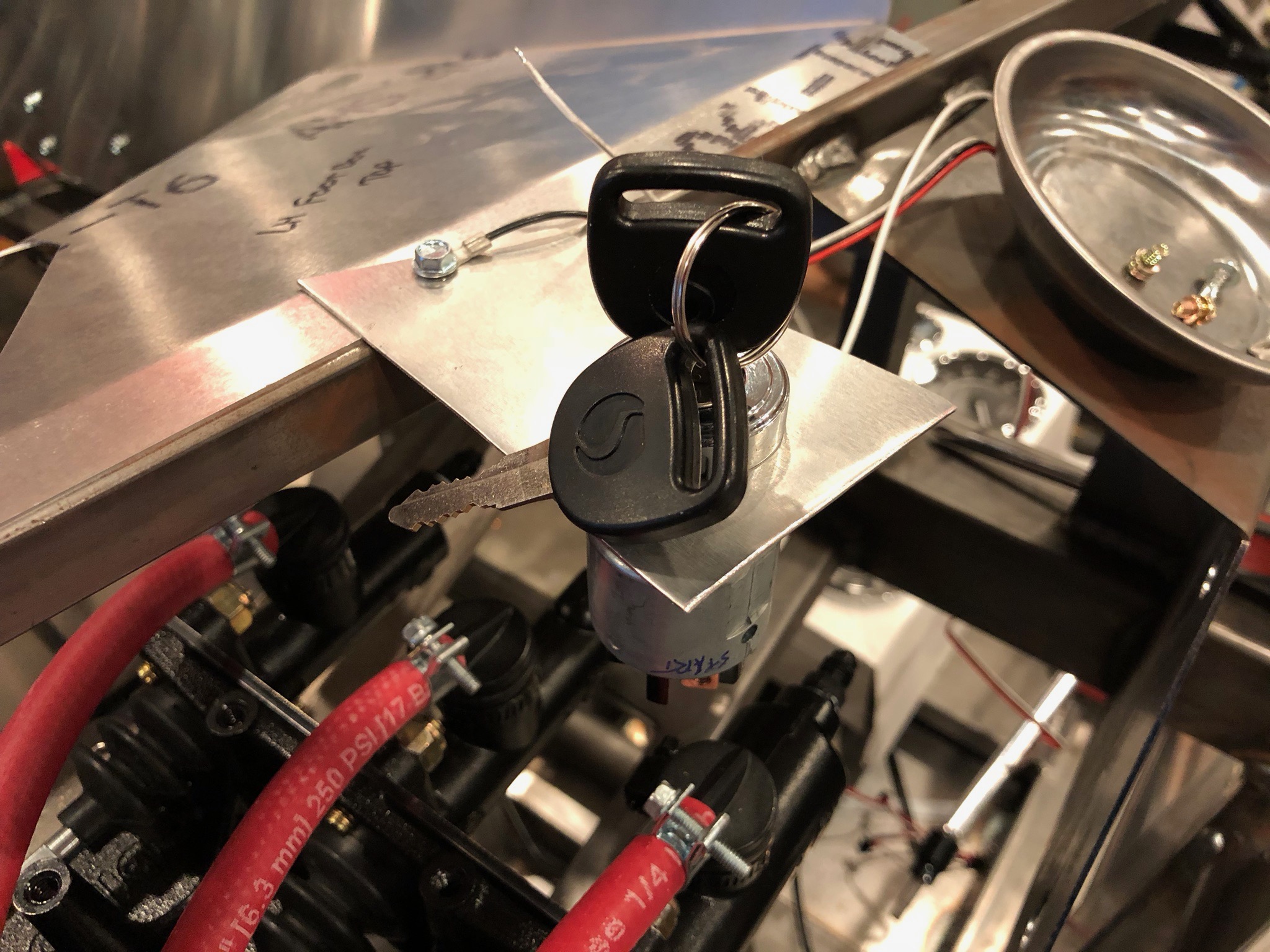
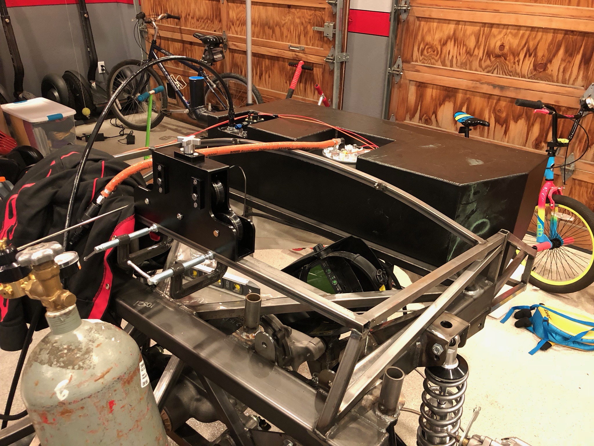
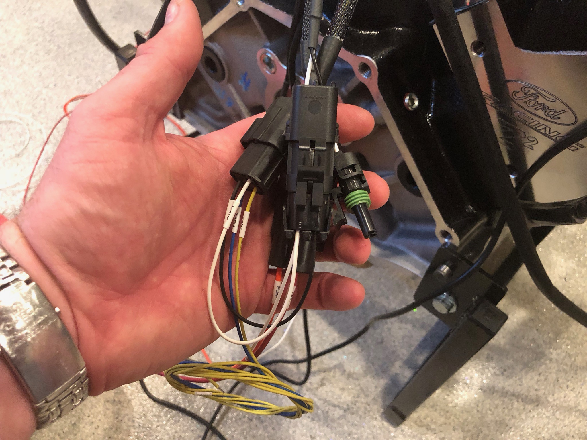
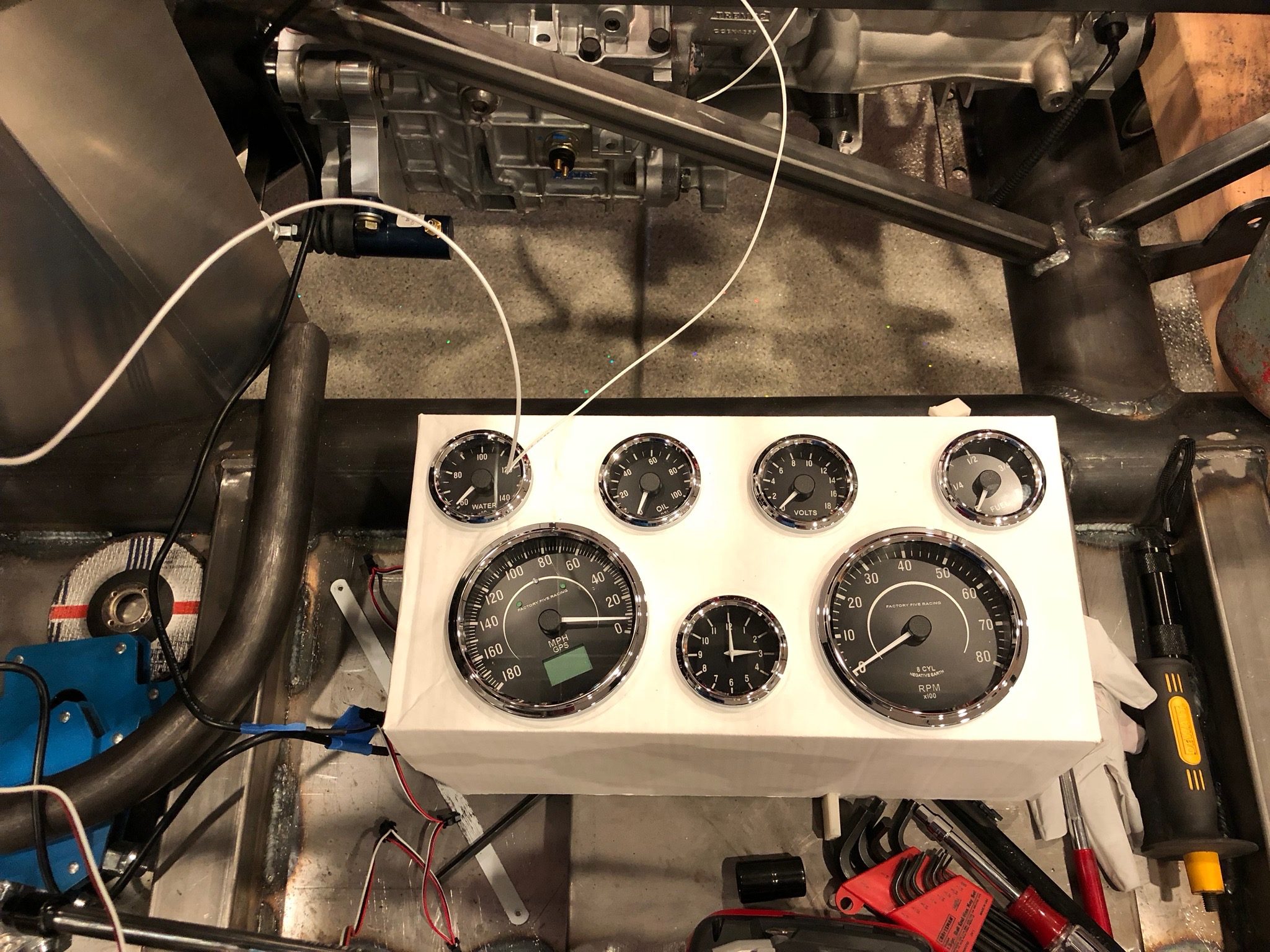
I don’t want to start the car unless I can monitor oil pressure at a minimum, but it’s minimal extra work to also hook up the coolant temperature gauge and tachometer. I had considered fabricating a larger aluminum plate to temporarily mount the gauges, but the cardboard box they came in will work just fine.

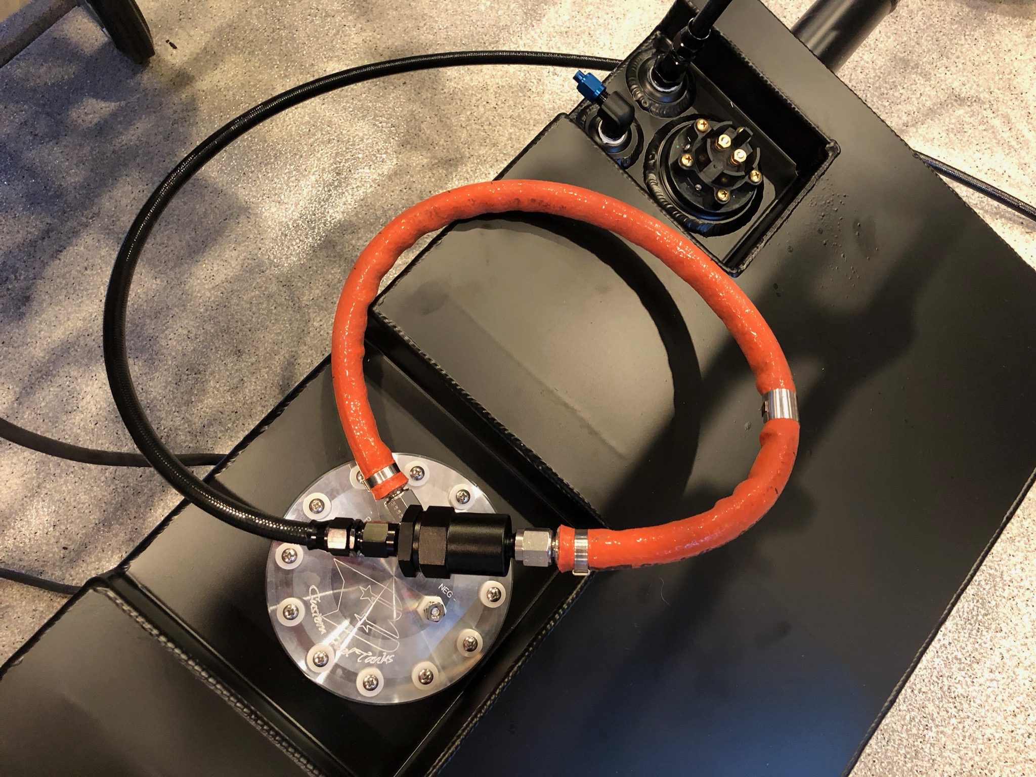
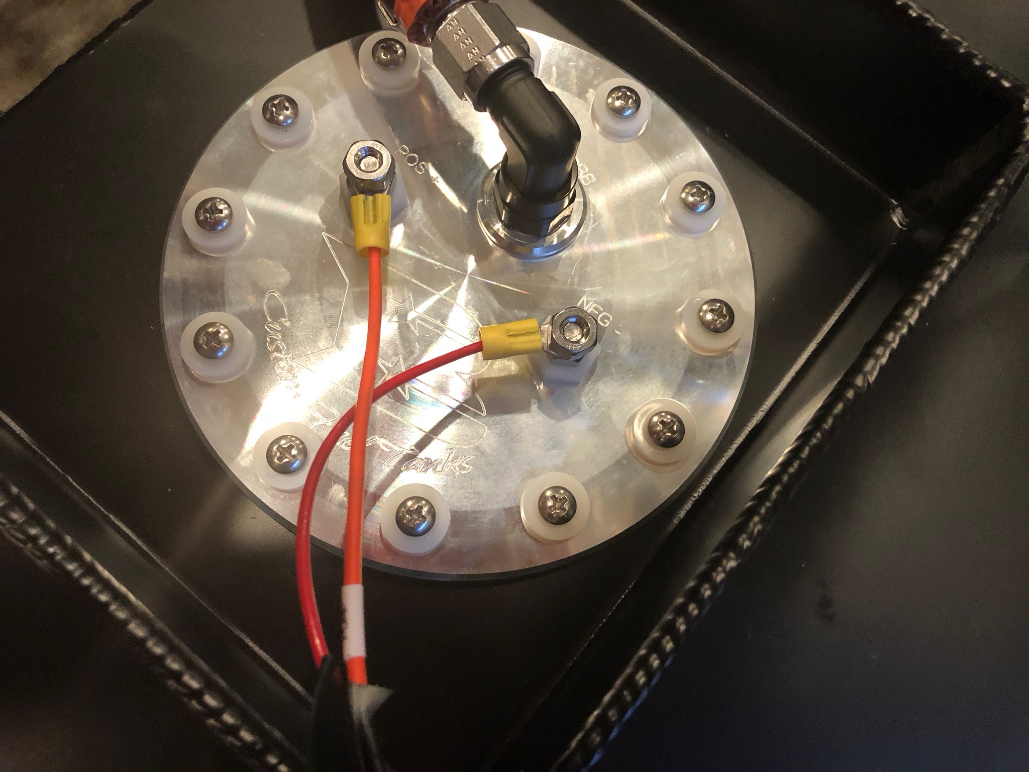
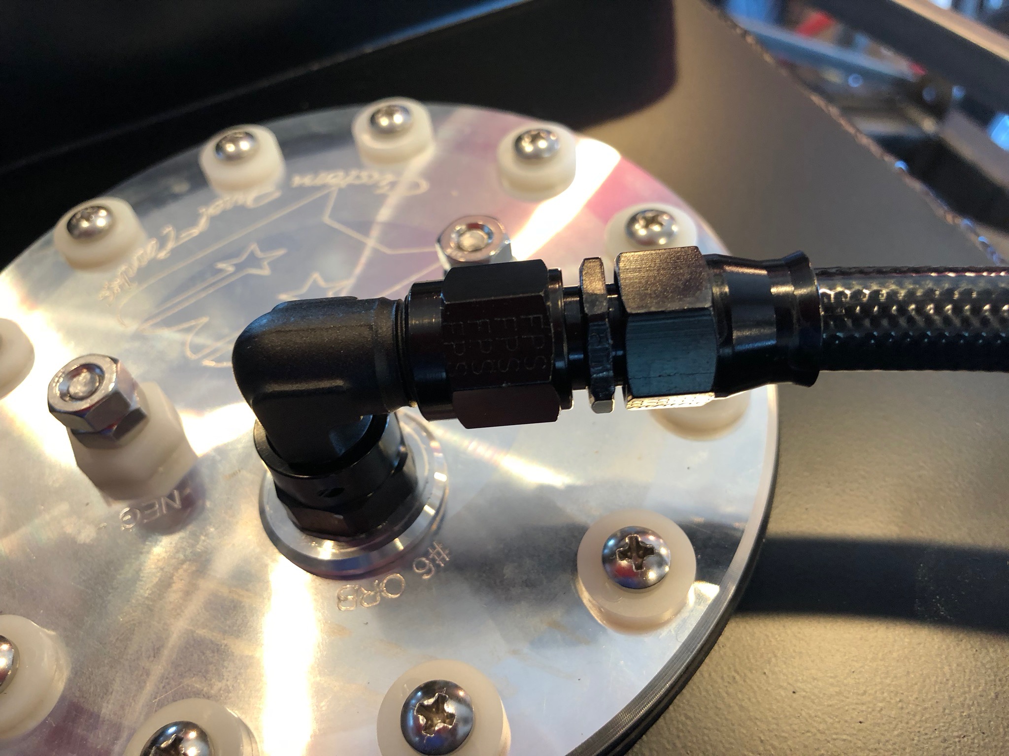
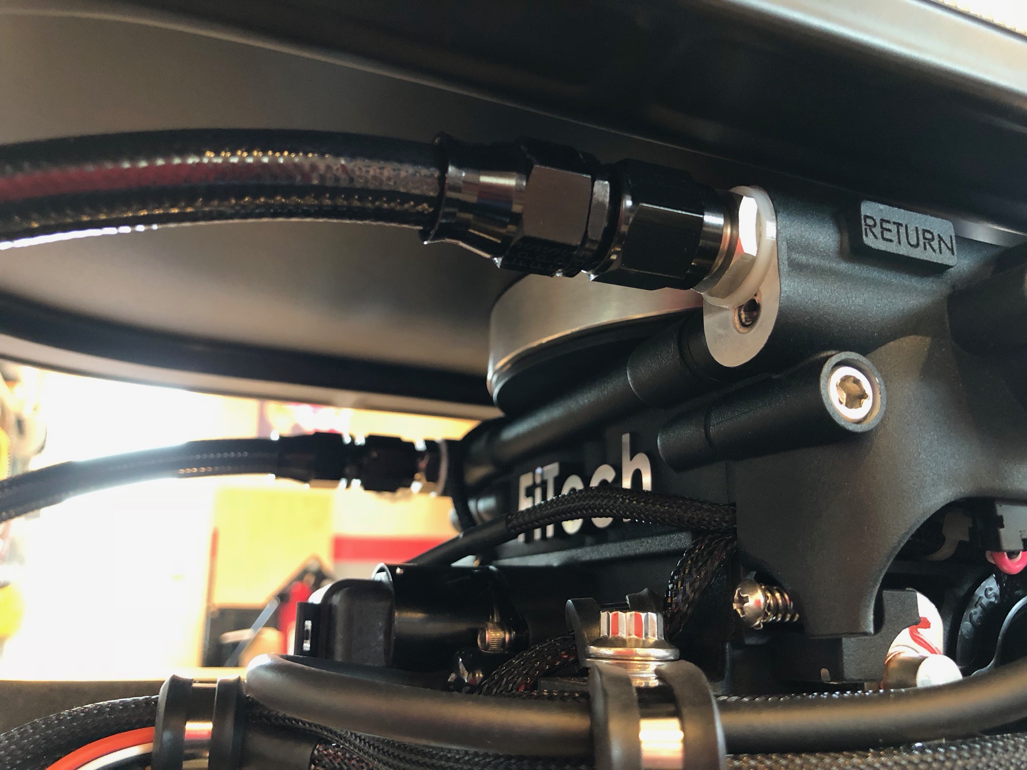
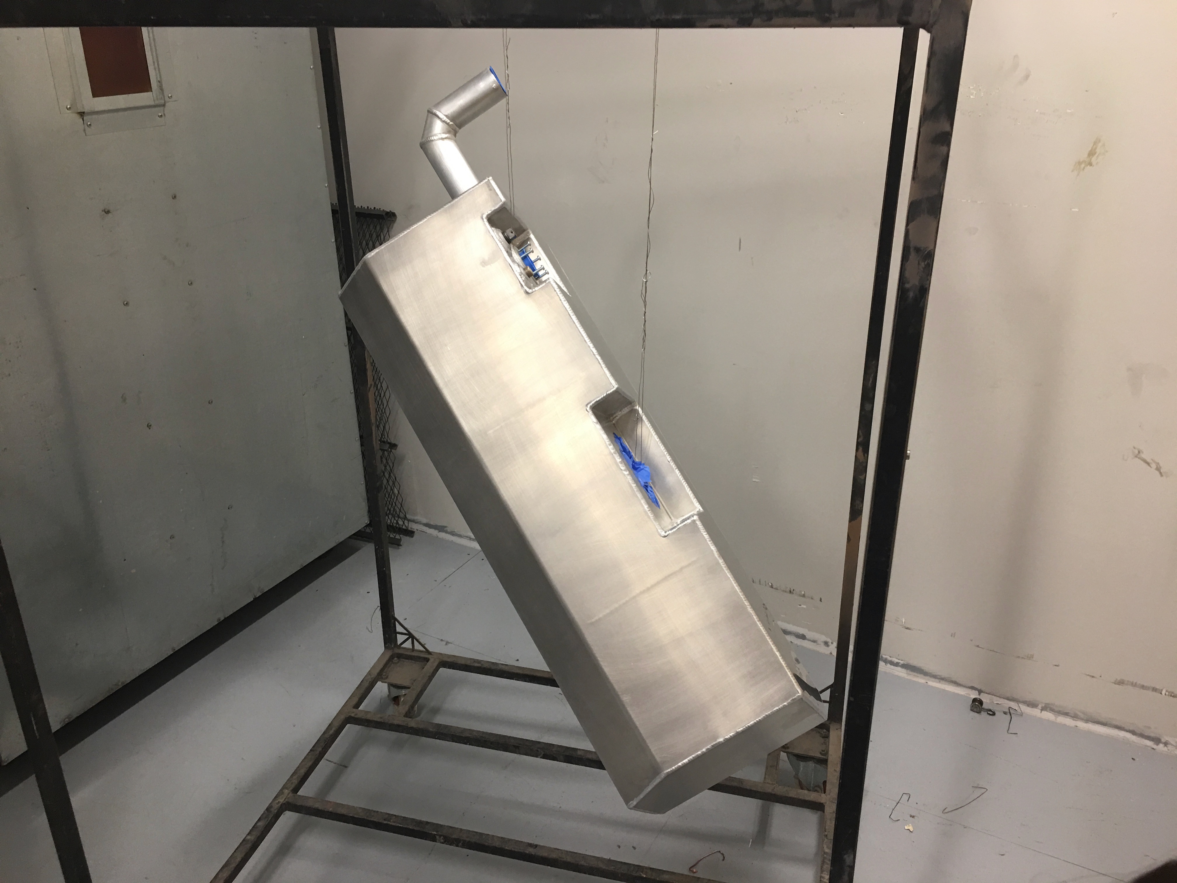
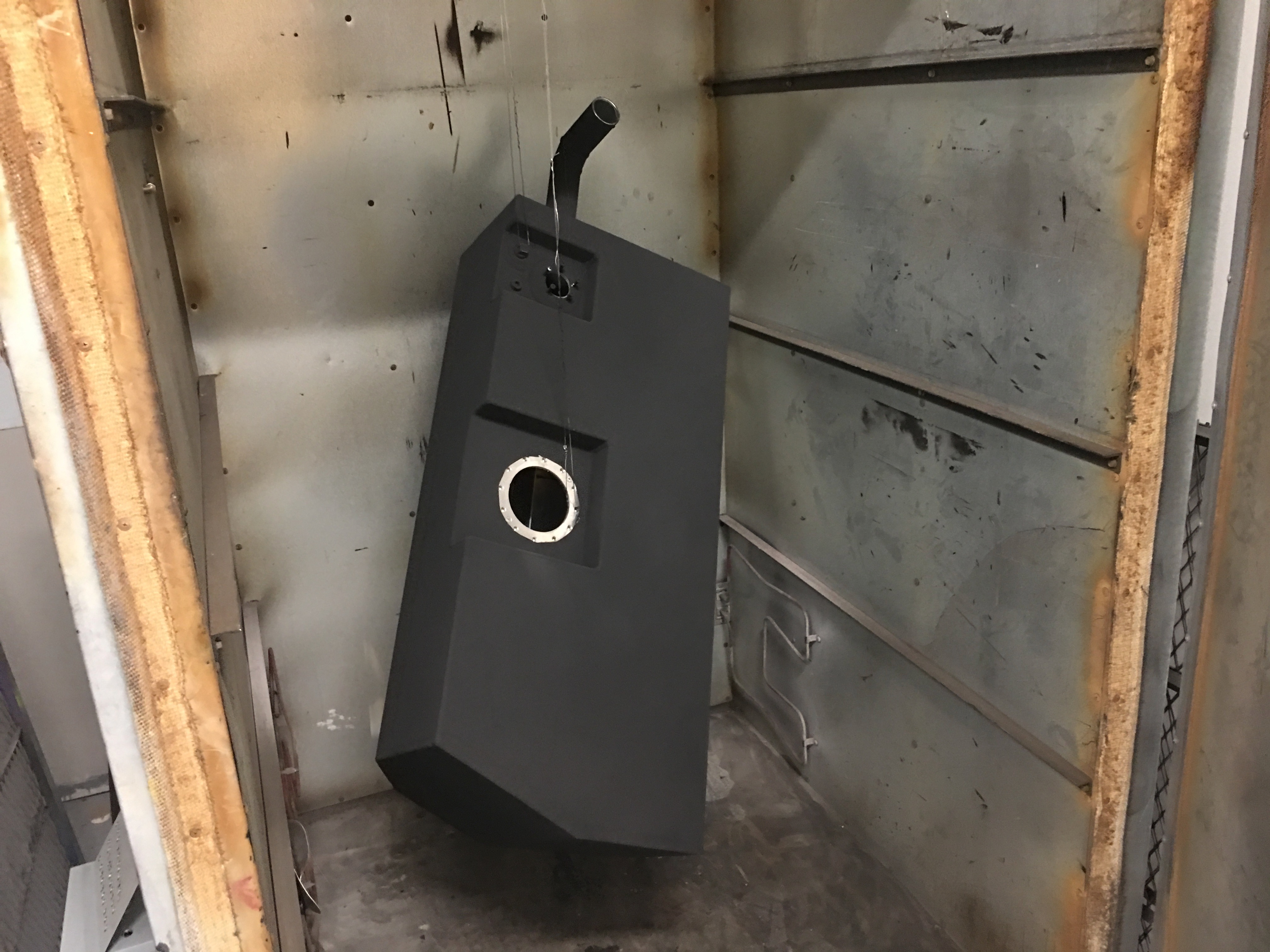
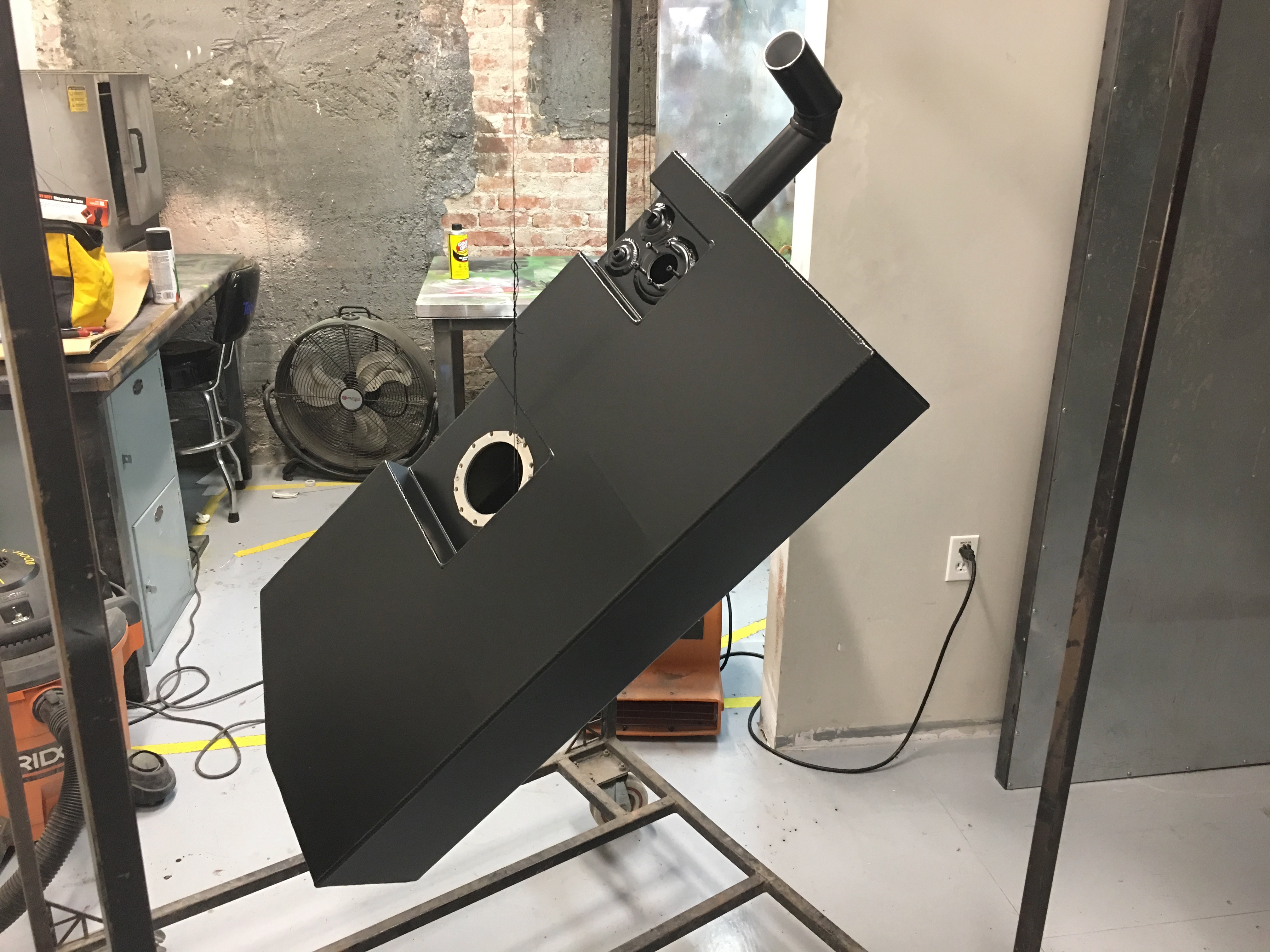
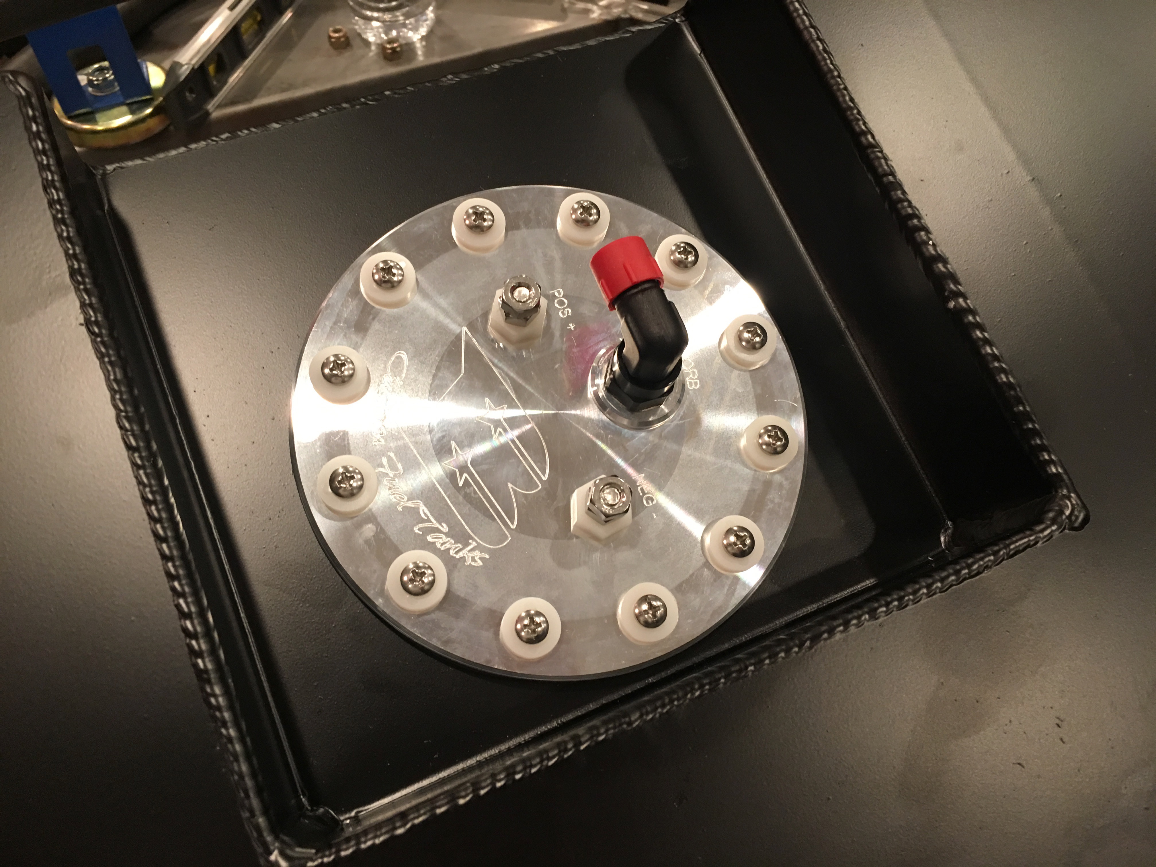
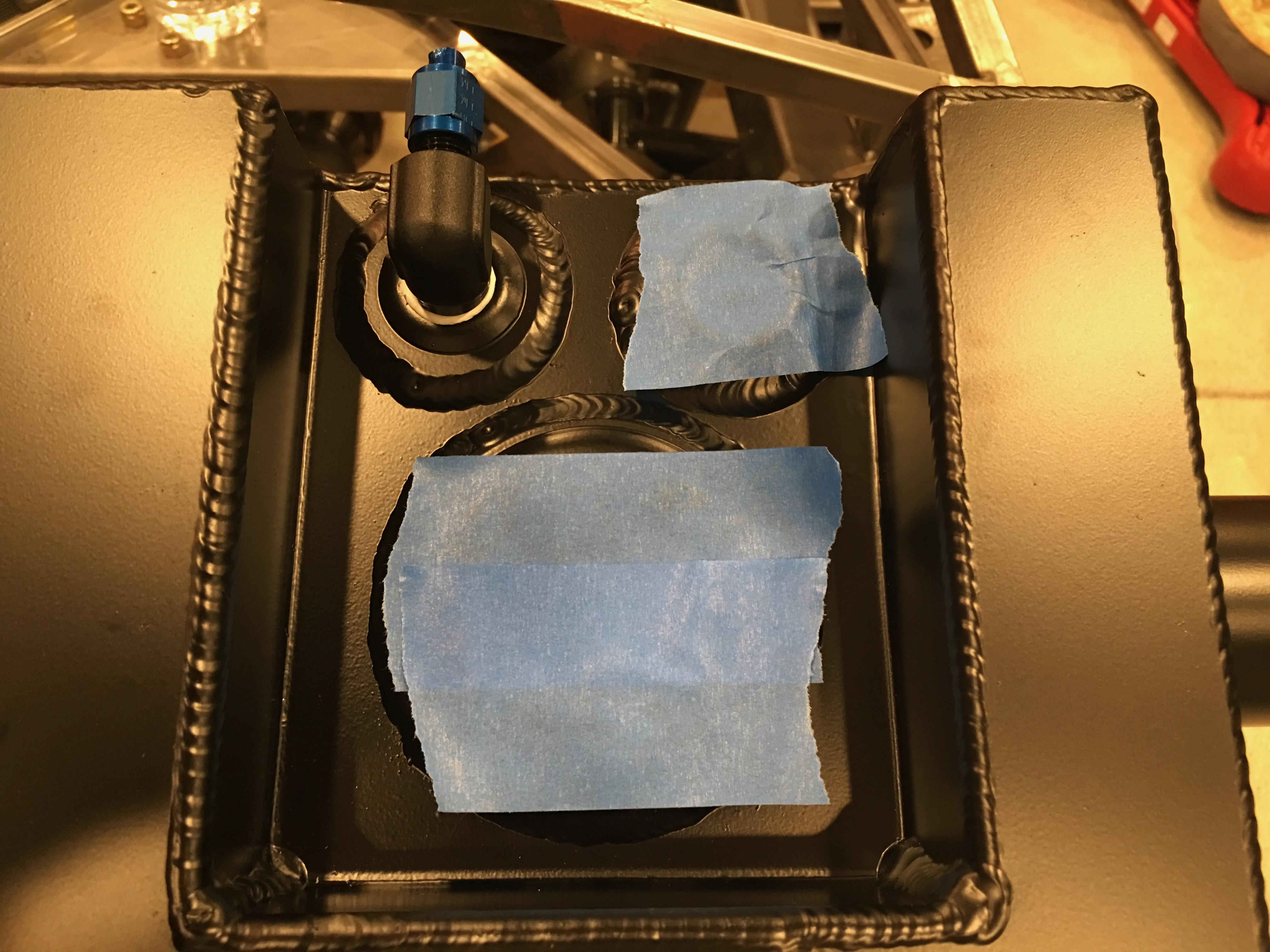
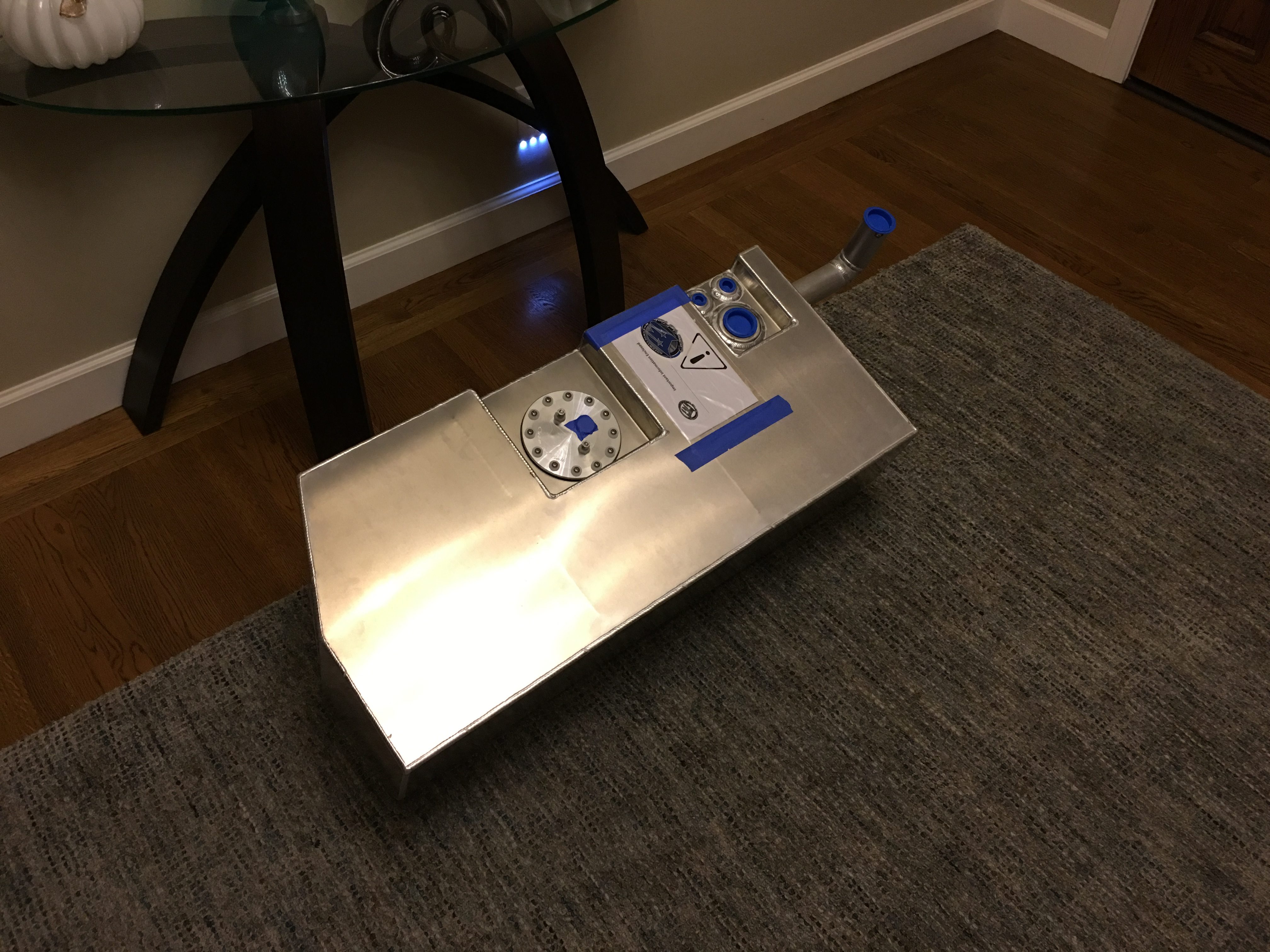
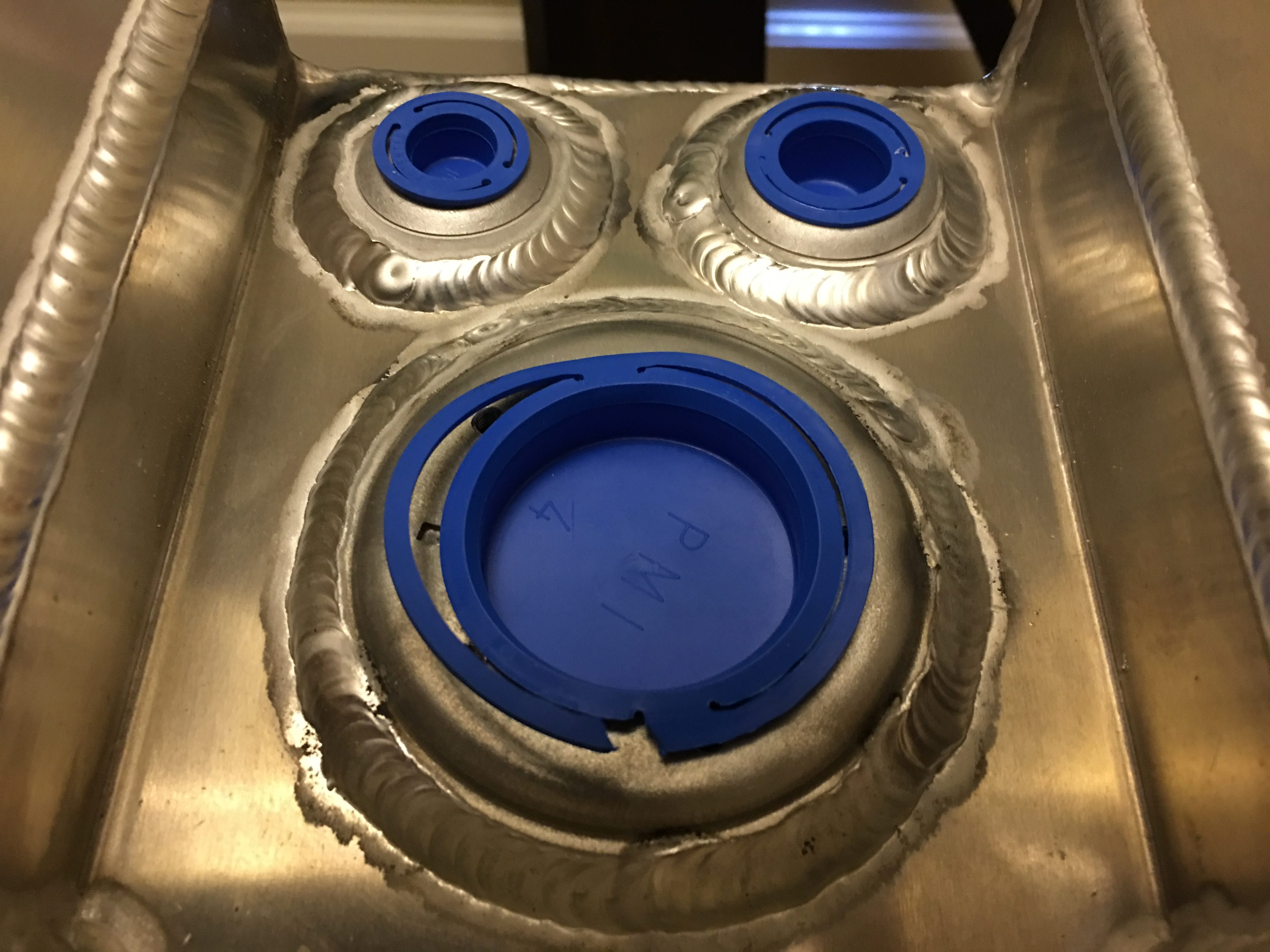
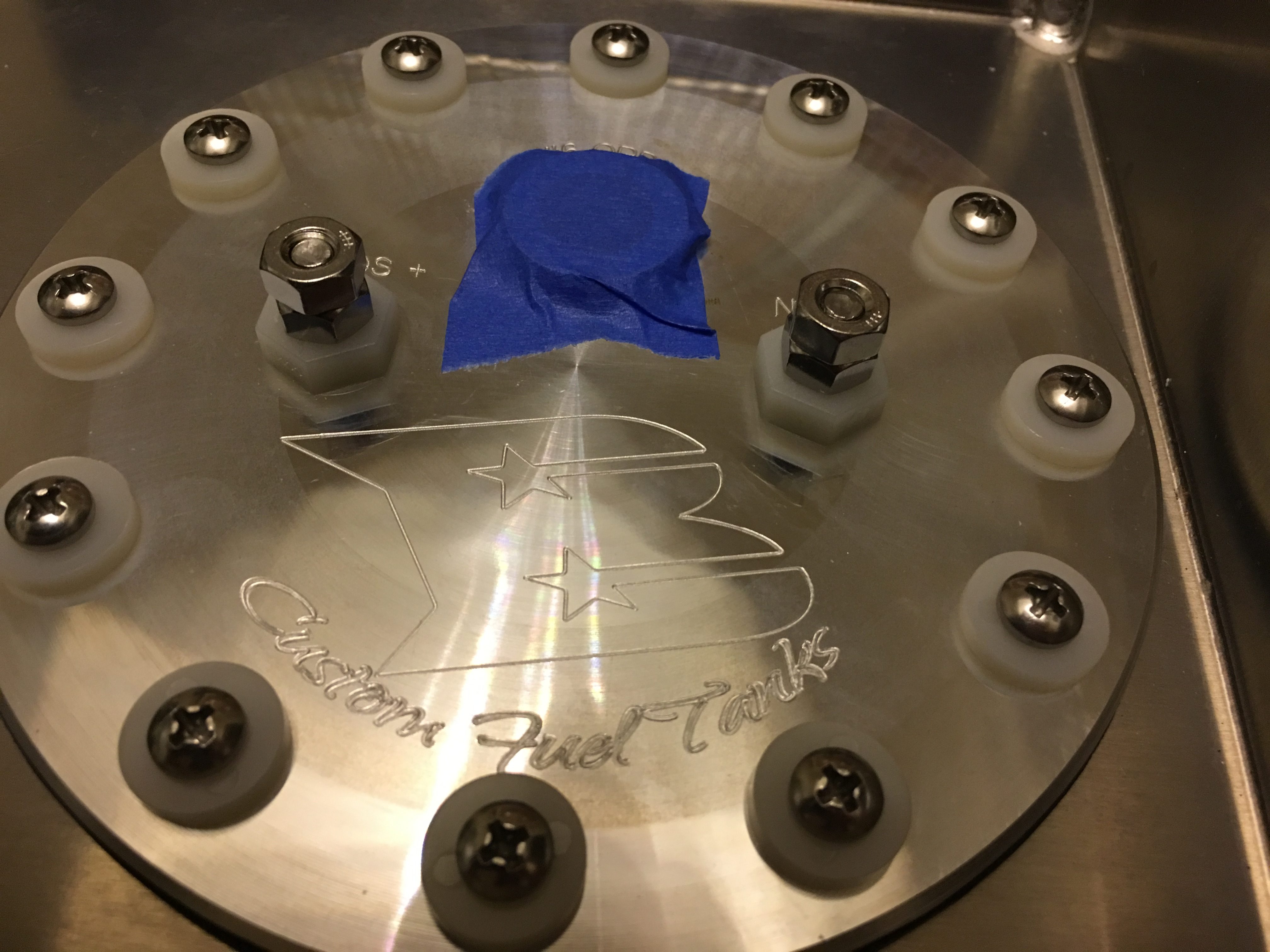
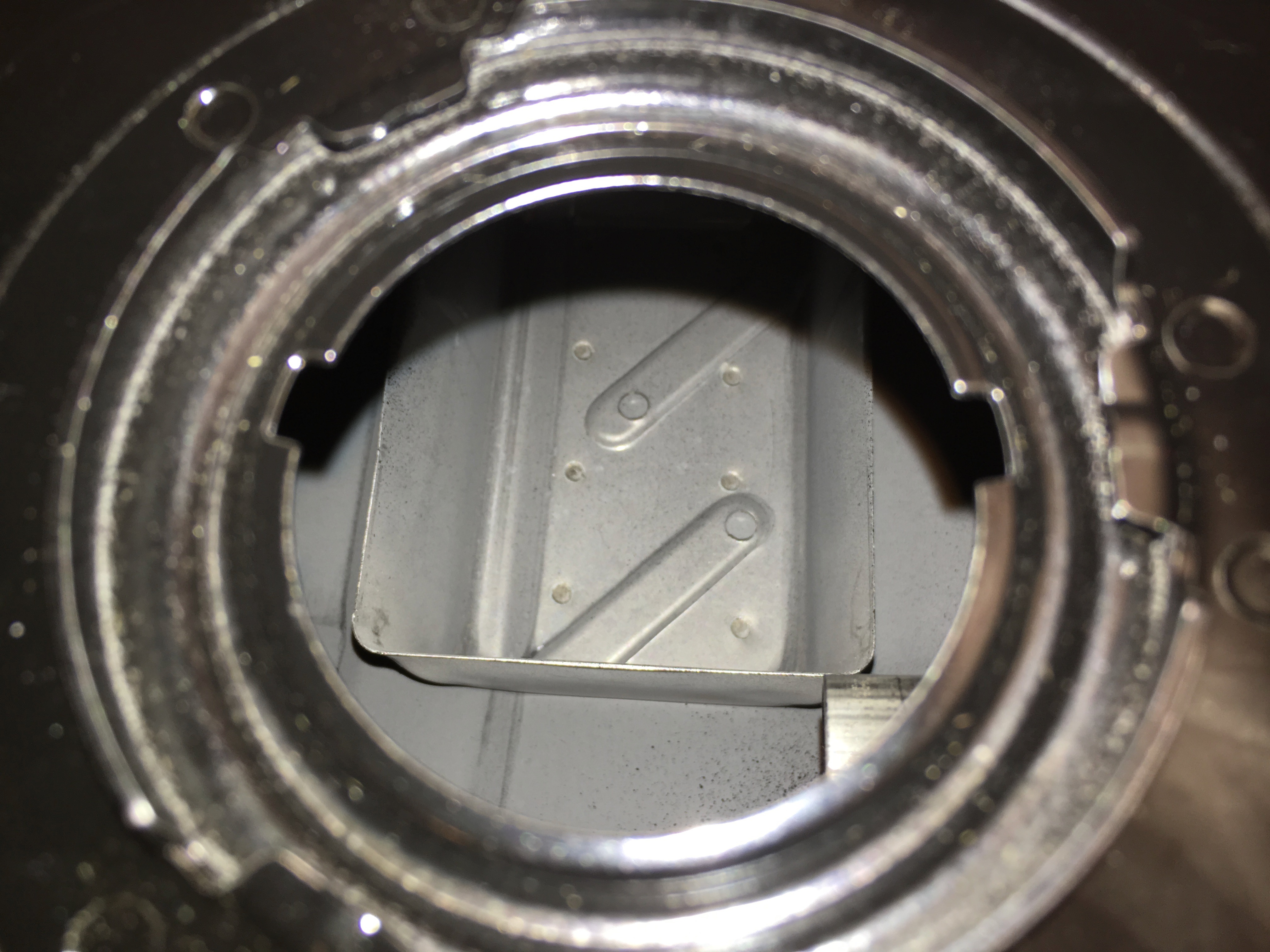
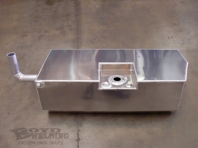
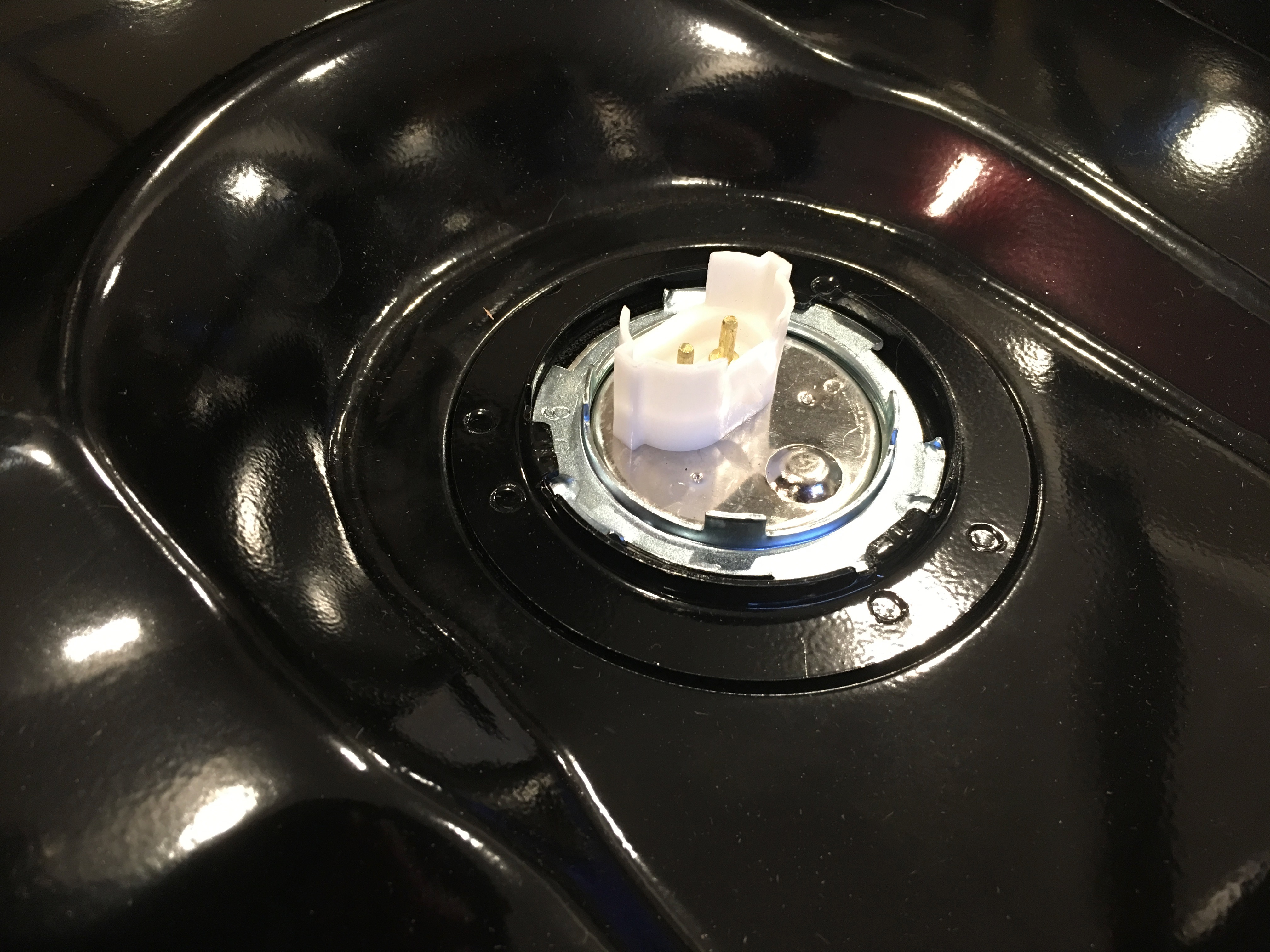
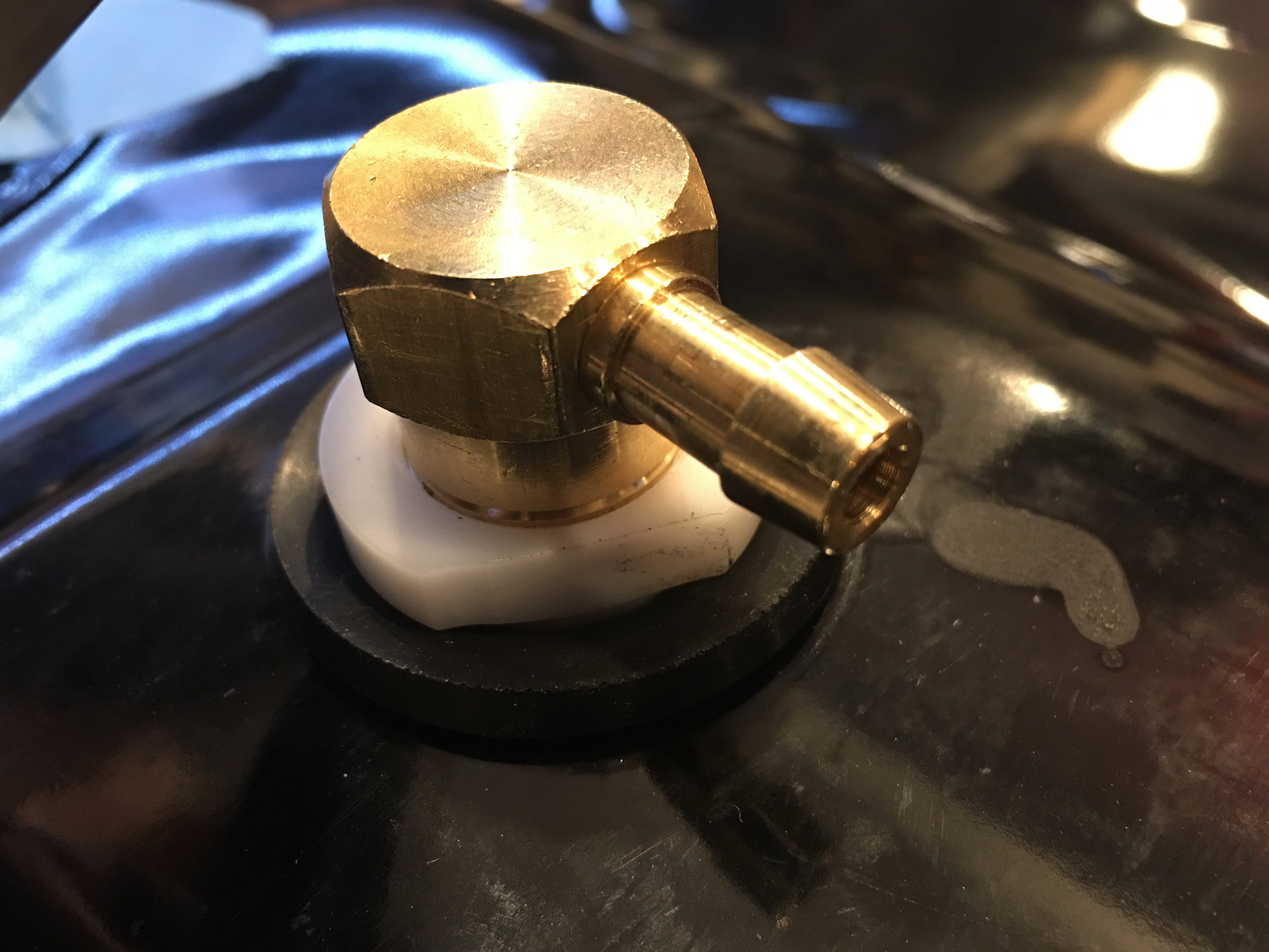
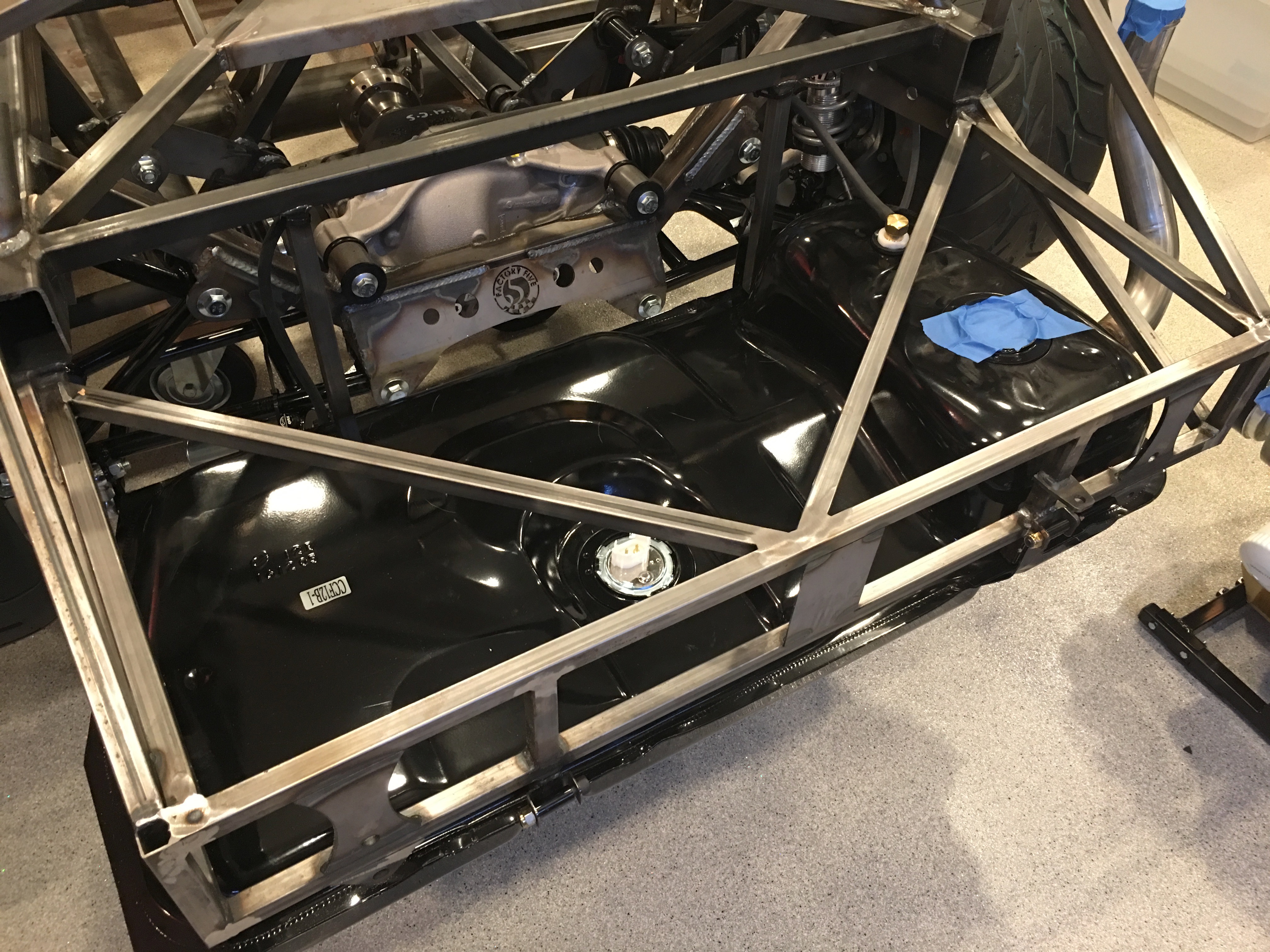
I also set the fuel tank on top of the rear part of the chassis and hooked up the fuel lines. This has 4-5 gallons of fuel in it right now, so it’s fairly heavy. I’ll probably end up burning off a good chunk of this doing some demo and tuning runs. I need to get this lighter before I start messing with mounting this in the rear of the chassis.

Prepping Engine for Dyno Shop

I’ve got a handful of details left to wrap up before we can run the engine at the dyno shop. First up, I needed to plumb the fuel filter between the fuel pump and the throttle body. I had a few scrap pieces of hose laying around from my airplane build, so I used one to insert the fuel filter into the supply line.

I also temporarily wired up the fuel pump to the FiTech unit. I’ll replace these terminals with better ones during the final wiring on the car, but this is what I had laying around that fit these large studs.

I also needed to wire up the ignition coil to the FiTech unit since it controls the ignition timing. Most of the car will be wired with automotive TXL insulated wire since that’s what comes in the Infinitybox wiring harness, but I don’t have any of that right now. I used some MIL-W-22759/16 wire I had laying around (which is better than the TXL wiring anyway). This cable snakes under the ignition coil (where it will be secured with a cushion clamp) and up behind the distributor where it follows the rest of the wires around the right side of the throttle body to the back of the engine.

The coil needs to be connected to two wires coming off one of the other FiTech connectors, so I looped them back. The white wire will also be connected to the switched side of the ignition switch.

Since I don’t want to mess with the key switch now, I just rigged up an old toggle switch to turn the ignition on and off.

I also temporarily attached the ground strap to the engine block. At the other end is the red wire that goes to the fuel pump ground. I didn’t have any 18+ ga black wire around, so I used red and flagged it with some black electrical tape. None of this will end up in the car.

While I had my tools out to install the WeatherPak connectors on the back of the engine, I connected the electric power steering motor to the controller.

Fabricated Temporary Fuel Hoses

In preparation for running the engine at the dyno shop, I fabricated a couple of hoses. I’m using Fragola stainless steel reinforced conductive PTFE hoses with a black nylon covering. For the dyno run, I just need a supply and return hose, so I cut the 20′ hose in half and installed straight fittings on each end.

Here’s where the supply and return lines attach to the back of the throttle body.

We also received our headers from GP Headers. These are ceramic-coated, stainless steel headers with double collectors so that the O2 sensor can be installed in the engine compartment.

These are really beautiful, especially compared with the ones from FFR. I installed the FiTech O2 sensor in the right side bung since the passenger side of the engine compartment is much less crowded.

The GP Headers have a much thicker flange (3/8″ vs 1/4″), so the 3/4″ bolts that came with the engine bolt kit aren’t long enough. There is only about 1/4″ of thread engagement in the block with these bolts, so I’m going to see if ARP will exchange these for 1″ bolts.

Finished up Distributor Wiring and Fuel Pump Installation

I received a new order from Summit Racing with some additional wire separators.

I used one on each side to keep the wires organized as they make their way up to the distributor. After installing the wire separators, I slid the heat-shrink wire labels in place and shrunk them down.

Here’s the other side.

I used a two-conductor wire separator behind the distributor to tie the #4 and #7 wires together. For some reason, they didn’t stock polished, two-conductor separators on Summit, so I ordered black anodized ones. This will largely be hidden under the air cleaner though, so I think black will be just fine. I can always sand off the anodizing and polish it if it’s too visible.

Here’s a shot of the whole engine with the distributor wiring all wrapped up. Only a few remaining details to wrap up before I can get the engine to the dyno shop.

I also received and installed the Classic Instruments tube type fuel level sender. This is a 0-90Ω sender that is compatible with the gauges from FFR. The tank is 10.75″ deep here, but this sender is only 10″ long below the flange. That leaves 3/4″ of unmeasurable fuel below the sender; given the taper of the bottom of the tank, that’s probably only 1-2 gallons of fuel. I’m fine  with a 1-2 gallon fuel reserve below the empty reading on the fuel gauge.

Powder Coated Fuel Tank

We’re going to need the fuel tank for the engine dyno run since the dyno shop is not set up to run EFI engines. The simplest solution is to bring my own tank and let the FiTech unit drive the integrated pump. Before I put fuel in the tank though, I need to get it powder coated since I wouldn’t want to put a tank with fuel vapors in the powder coating oven.

I pulled the fuel pump so that I just have the bare tank and then used some scotchbrite pads to rough up the surface to give the powder coating a better grip. After cleaning the tank thoroughly with solvent, I hung it from a couple of the trolleys in the loading rack.

After giving it a thorough coating of powder, I transferred it into the oven.

After 30 minutes or so at 400ºF, I transferred it back to the loading rack and set it in front of the exhaust racks to get some cooling airflow.

After bringing it home, I reinstalled the fuel pump and fuel outlet fitting.

I also installed the fuel vent fitting and capped it until I am ready to hook it up.

I purchased a 90º angle for the fuel return, but unfortunately it won’t work since Boyd put the boss too close to the side wall of the recess. A straight fitting would obviously thread in fine, but I think it would push the hose up too high since the top of the tank will only sit 3/4″ below the trunk floor. I’ll have to figure out another solution here.

Fuel Injection Wiring and Fuel Tank

I picked up some stainless steel cushion clamps and used a few to secure the FiTech throttle body wiring. There are three bundles of wires coming off the front of the unit (including the one that drops under the intake runners and connects to the coolant temperature sensor).

The remaining two, plus all of the wire bundles that come off the back of the unit are collected into one cushion clamp that is centered behind the throttle body. Fortunately, there are a couple of unused threaded bosses on the back of the throttle body that can be used to secure things. Once the air cleaner is installed, these should be nearly invisible.

Our Boyd Welding fuel tank showed up today. This is a beautiful piece of work and comes with an Aeromotive 340 Stealth fuel pump pre-installed.

The right side of the tank contains fittings for the fuel return and vent (the small fittings at the top) and the fuel level sender (the large fitting at the bottom). I’ll need to determine which fuel level sensor should be installed here since the one from FFR doesn’t look like it’s compatible.

The fuel pump is installed behind a custom machined mounting plate that has the fuel outlet fitting and electrical connections.

Fuel Tank and Steering Rack

We’re planning on running a FiTech EFI on our engine. The best way to set up an EFI system is an in-tank fuel pump since you really don’t want high-pressure pumps to pull fuel and it’s much easier for an external pump to lose its prime and cause the engine to die. I had planned on using FiTech’s new HyFuel in-tank retrofit pump, but the OEM tank from FFR is not ideal for this pump. The pump needs to mount on a fairly flat spot on the tank, but you really want the pickup to sit in the baffled part of the tank. Unfortunately, the baffle is pretty small in this tank and there is no flat spot above the baffle that will work without extensive modification to the tank.

After a bit of research, I’ve decided to ditch the OEM tank and I’ve ordered a Boyd Welding aluminum tank with built-in Aeromotive 340 Stealth pump. This pump will work fine with the FiTech EFI unit and is already installed for less than it would cost to buy the pump separately.

I got back to wrapping up the steering linkage. Unfortunately, I realized that I installed the steering arms upside down way back when I assembled the front spindles. Even more unfortunately, they can’t be removed without completely removing the spindle from the control arms. I purchased a ball joint separator and removed the spindles. Since I had them apart, I went ahead and swapped the ball joint boots with the ones I purchased from Energy Suspension.

Here’s the lower boot (highly deformed since the suspension is unloaded).

Here’s the upper boot (also fairly deformed). These are made from polyurethane and are quite a bit tougher than the ones that came off the ball joints. I’m glad I replaced these since both upper boots had already torn from the pressure on them when the suspension is unloaded.

I adjusted the length of the tie rods until the wheels are roughly aligned. This is probably as close as I can get this until the car is sitting on its tires at roughly the driving weight.

Steering and Fuel Tank

I started installing the steering system by installing the bearing block in the firewall and slipping the steering shaft up through it.

I then installed the steering rack into the front of the chassis. The brackets needed some bending to allow the mounting lugs to fit and the elongated hole on the left side (right in this picture) needed to be elongated further on the front bracket to allow the rack to slide far enough to the left to get the right bolt installed.

I installed the upper pillow block and slipped the upper steering shaft through and into the lower shaft to lock in the final position.

I ordered an electric power steering system from Erik Hansen on the FFR forum. After grinding and filing the bracket on the left to fit over the 3/4″ tube, I test fit it along with the bracket on the right until it’s roughly centered around the shaft. The instructions specify how far down the steering shaft it should be installed, but that puts the bracket quite a bit farther forward than this. Ordinarily, that wouldn’t be a problem, but the fat tire F panel will interfere with the bracket as well as the motor if I move it farther forward (I might even need to move it farther back from here)

Here’s the motor that will be installed inline with the steering shaft. I need to confirm that moving it back this much won’t cause any interference with the engine, but I think it will be fine.

I’ve been looking for a spot to mount the remote reservoirs for our quad-adjustable shocks, but I was concerned that the fuel tank will limit accessibility. I figured the easiest way to make sure was to just install the tank. Before doing so, I installed the fuel level sender in the center of the tank.

I also installed the vent at the highest point in the tank.

Finally, I installed the tank in the car.

Getting the tank up high enough to start the bolts required bending the flanges down where the tank sits against the bottom of the square tubing. Finally, I zip tied the vent tubing to the 3/4″ tubing, running it up and over to the left side of the car (though I’m not sure if this will be the final routing).