Installed Hydraulic Clutch

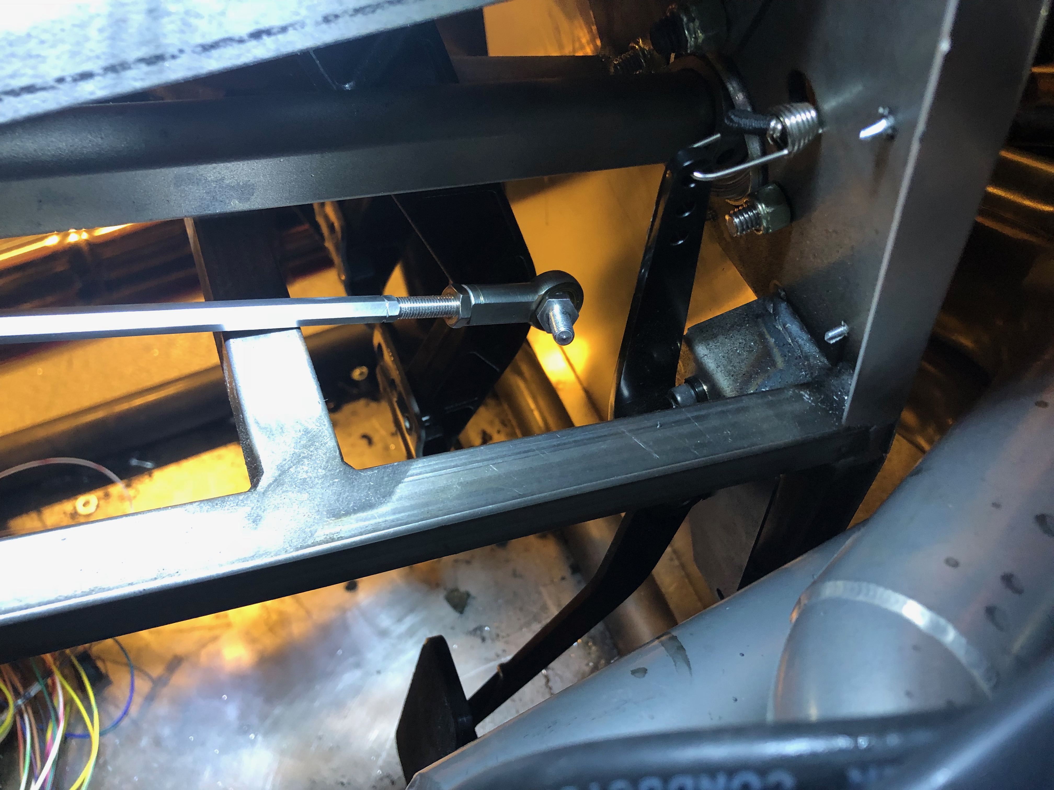
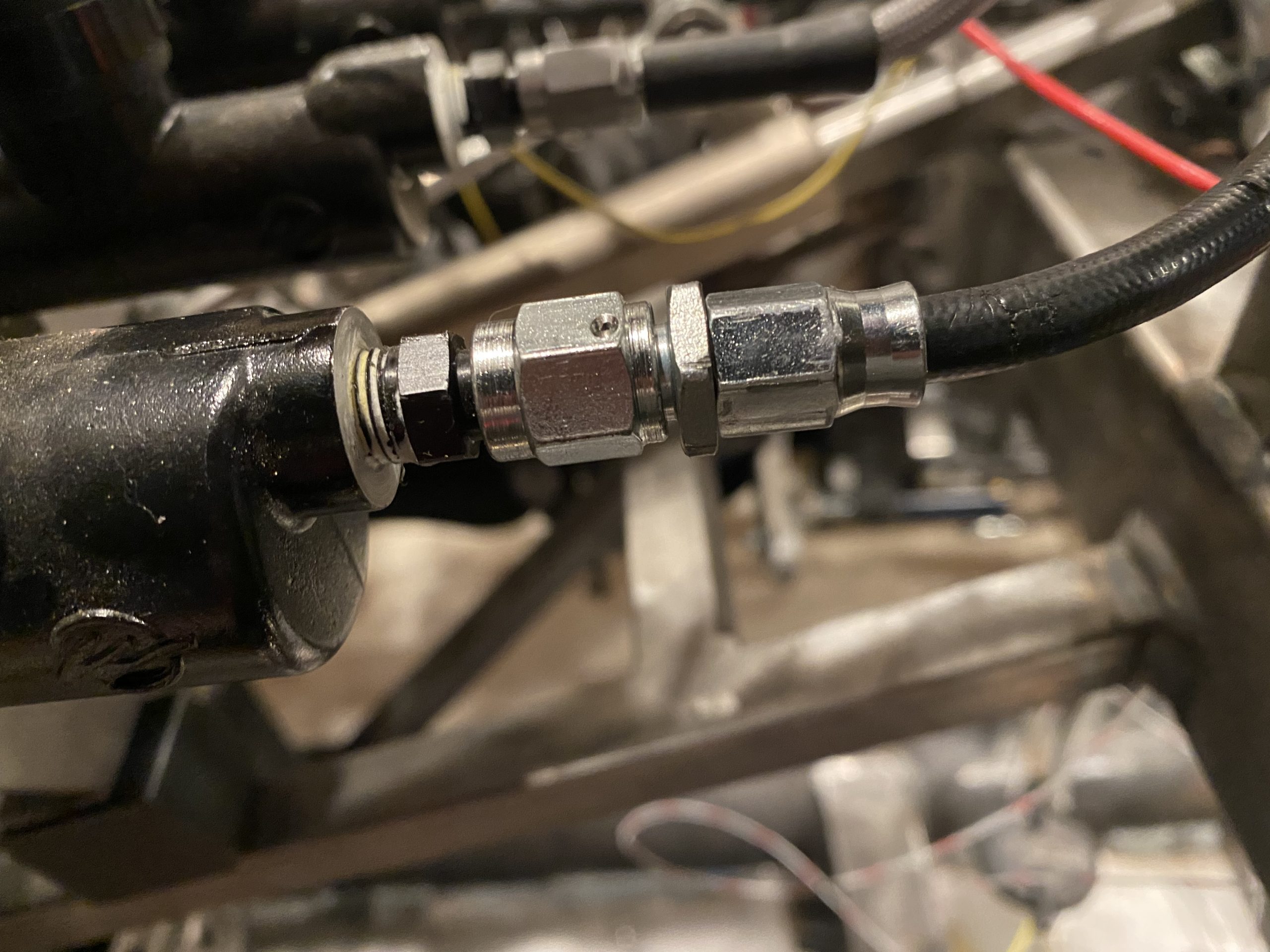
One of the few things left to do before I can go-cart the cart is to get the hydraulic clutch working. I cut the 3/16″ hose to length and installed the hose end. These are always a pain in the ass, but I think this is the last one I need to do in the car.

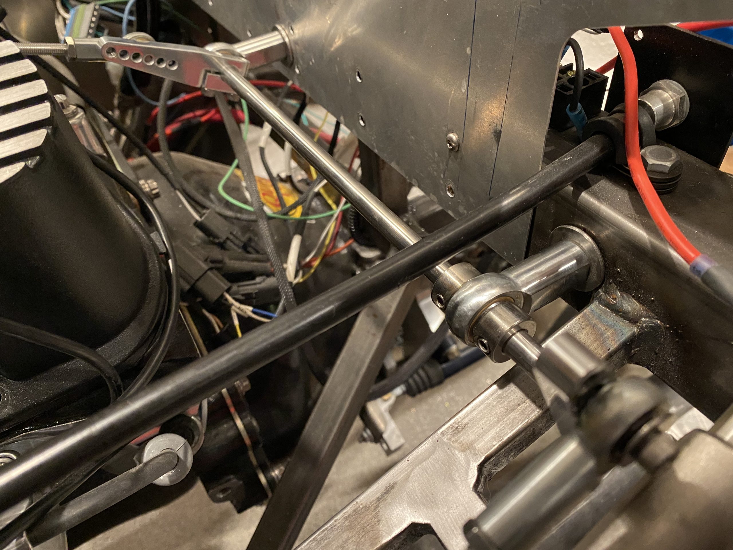
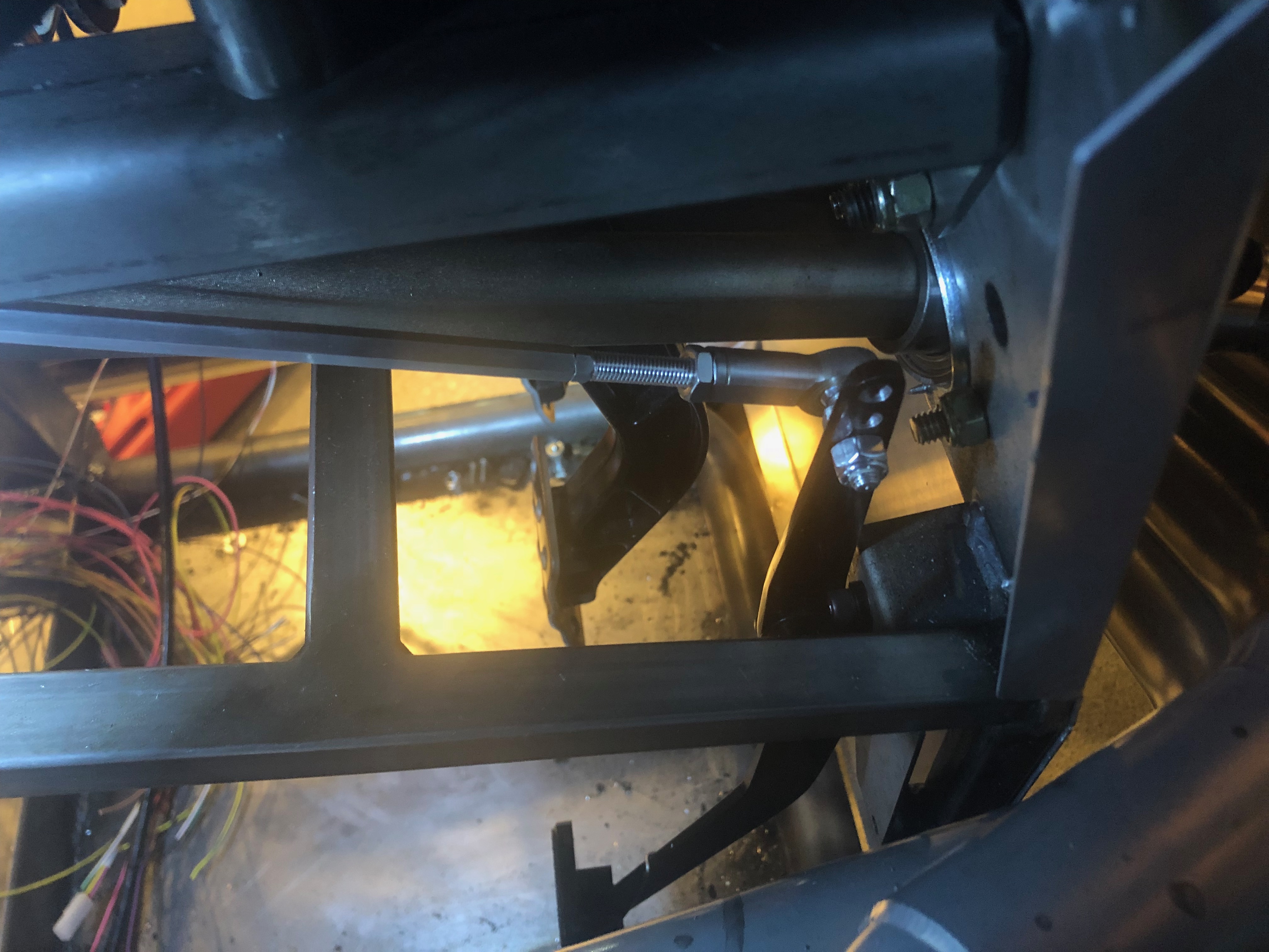
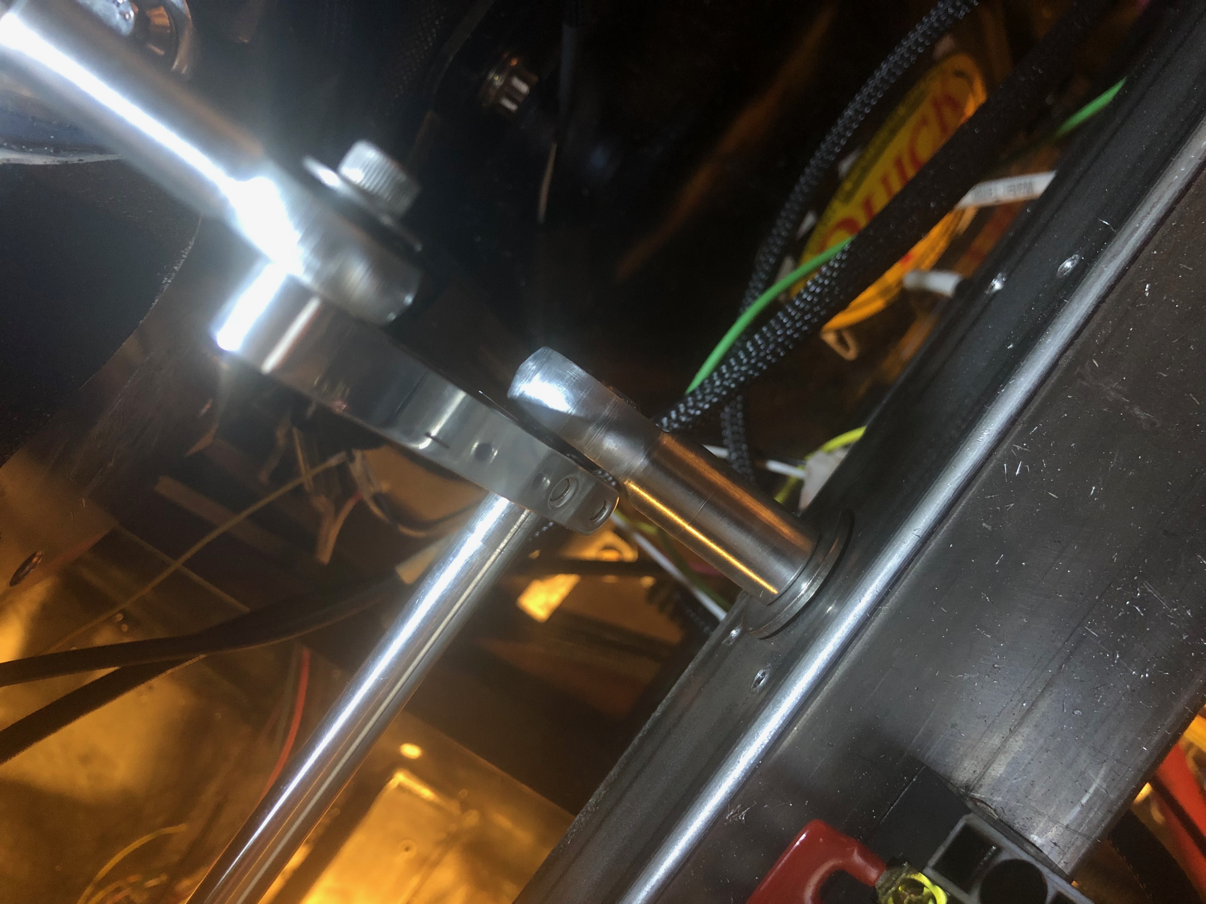
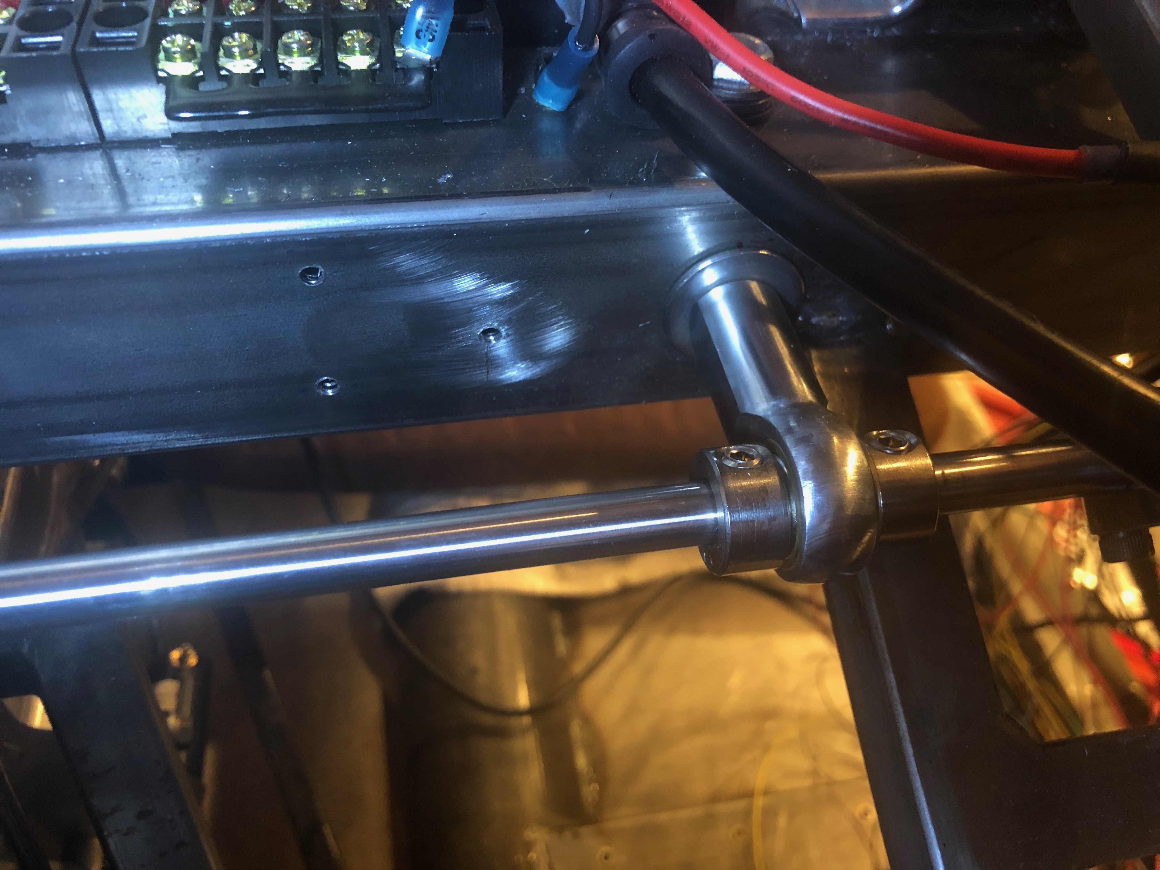
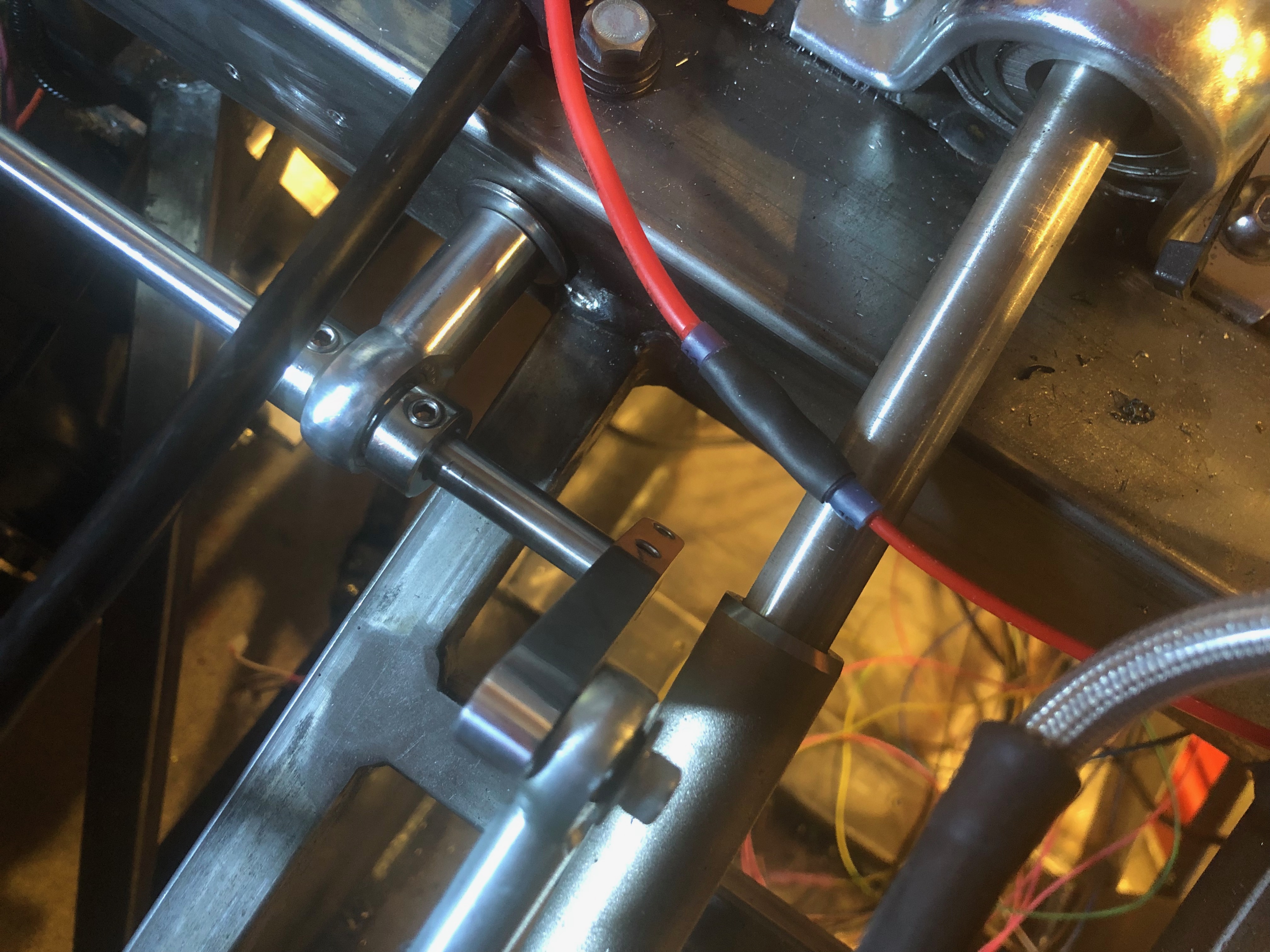
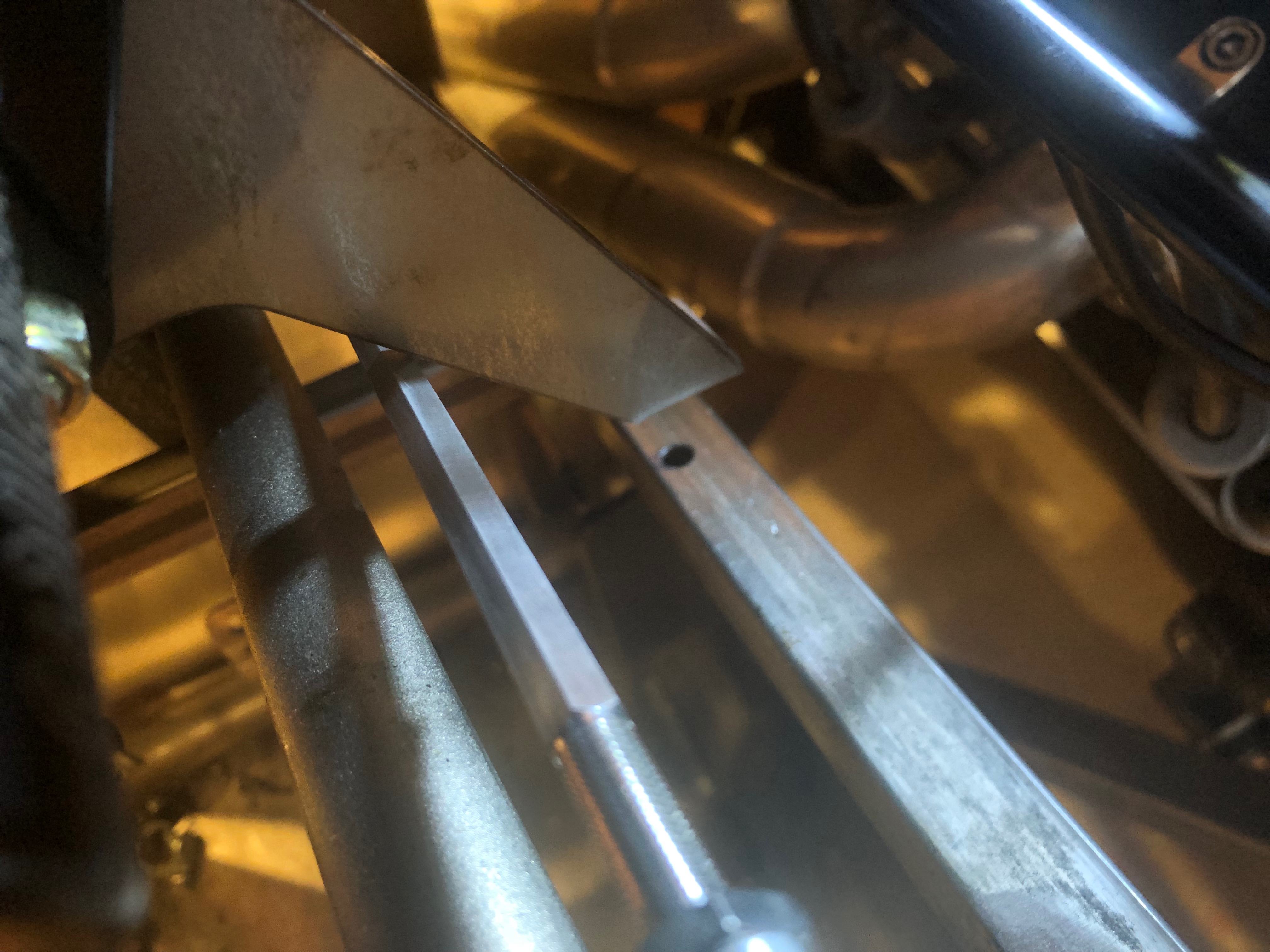
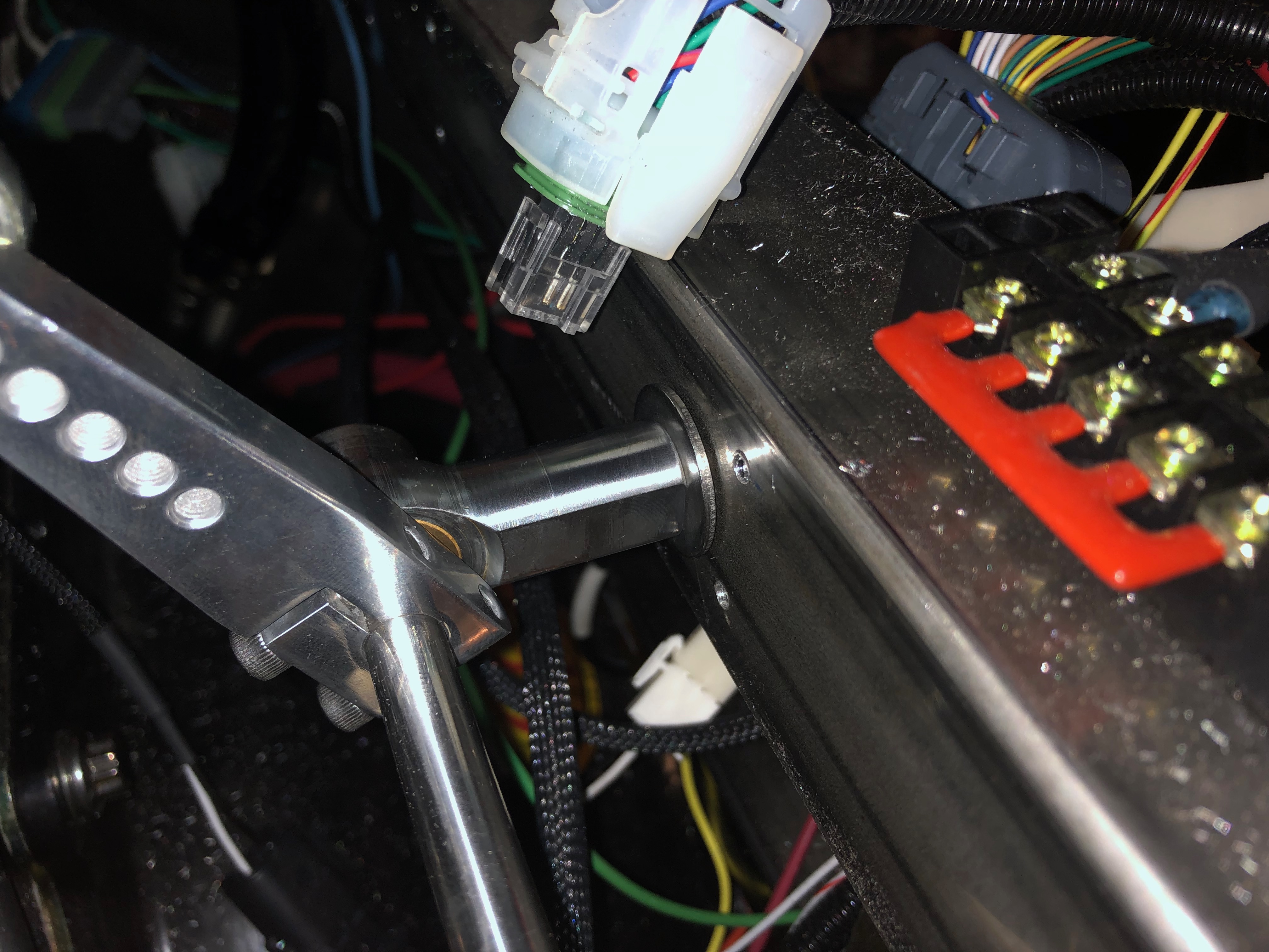
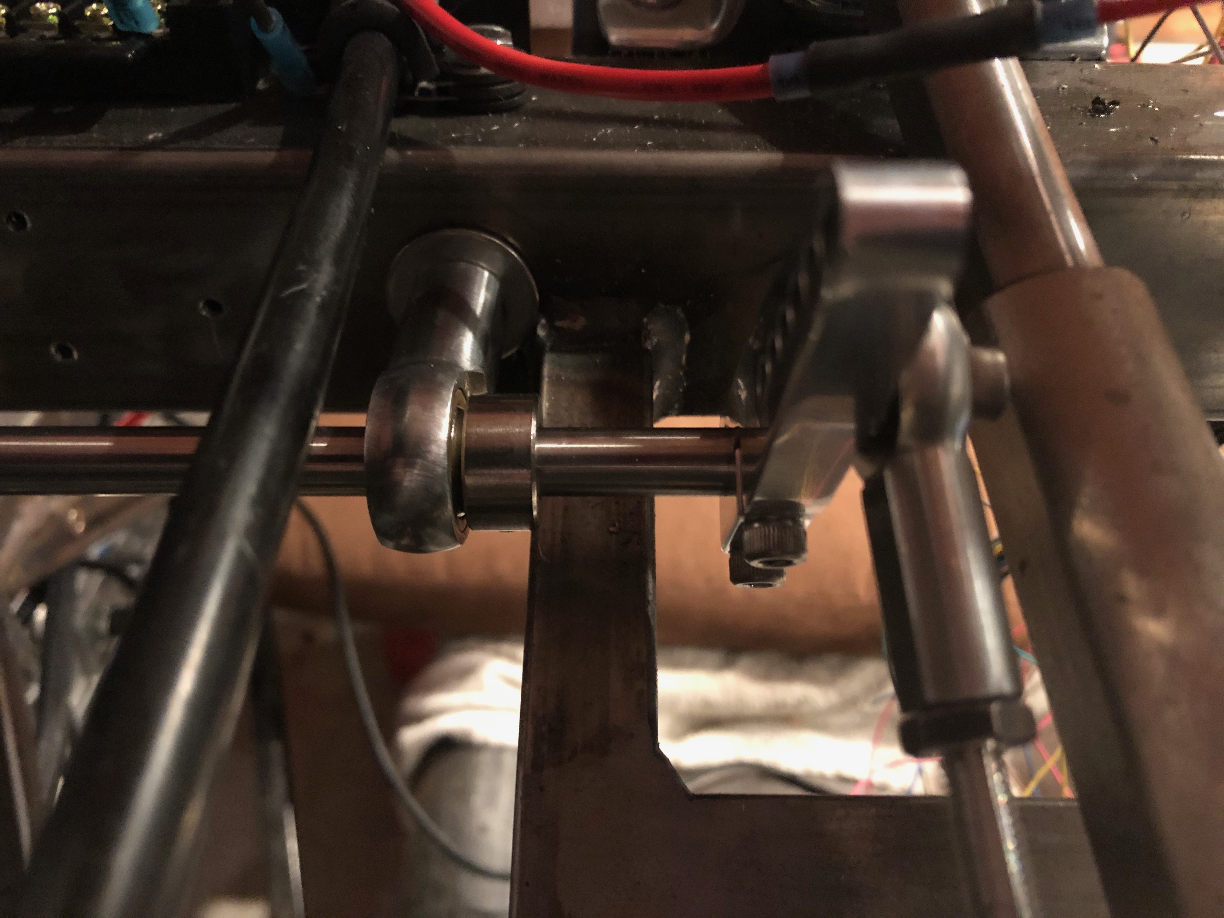
After installing it, I filled the reservoir with DOT 4 brake fluid and bled the system. I needed to adjust the clutch pedal to get a little more throw in order to release the clutch. The master cylinder has an adjustment on the pushrod which is easy to reach right now. I hope I never have to adjust them once the body is on the car because all of the access with be from below or through a small access panel in the engine compartment.

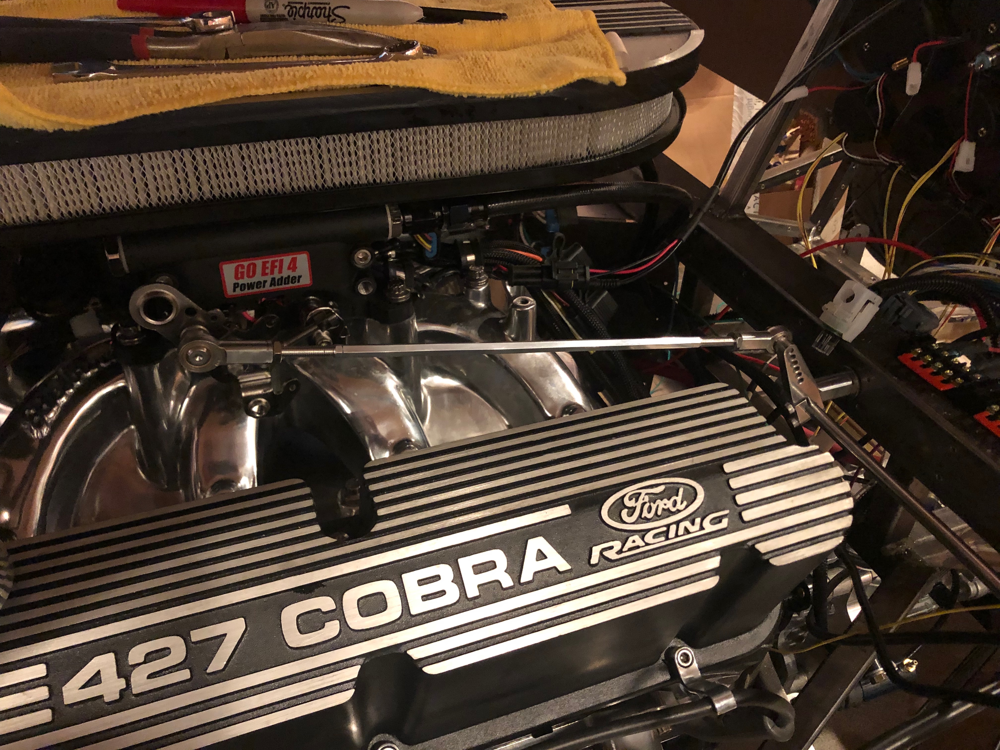
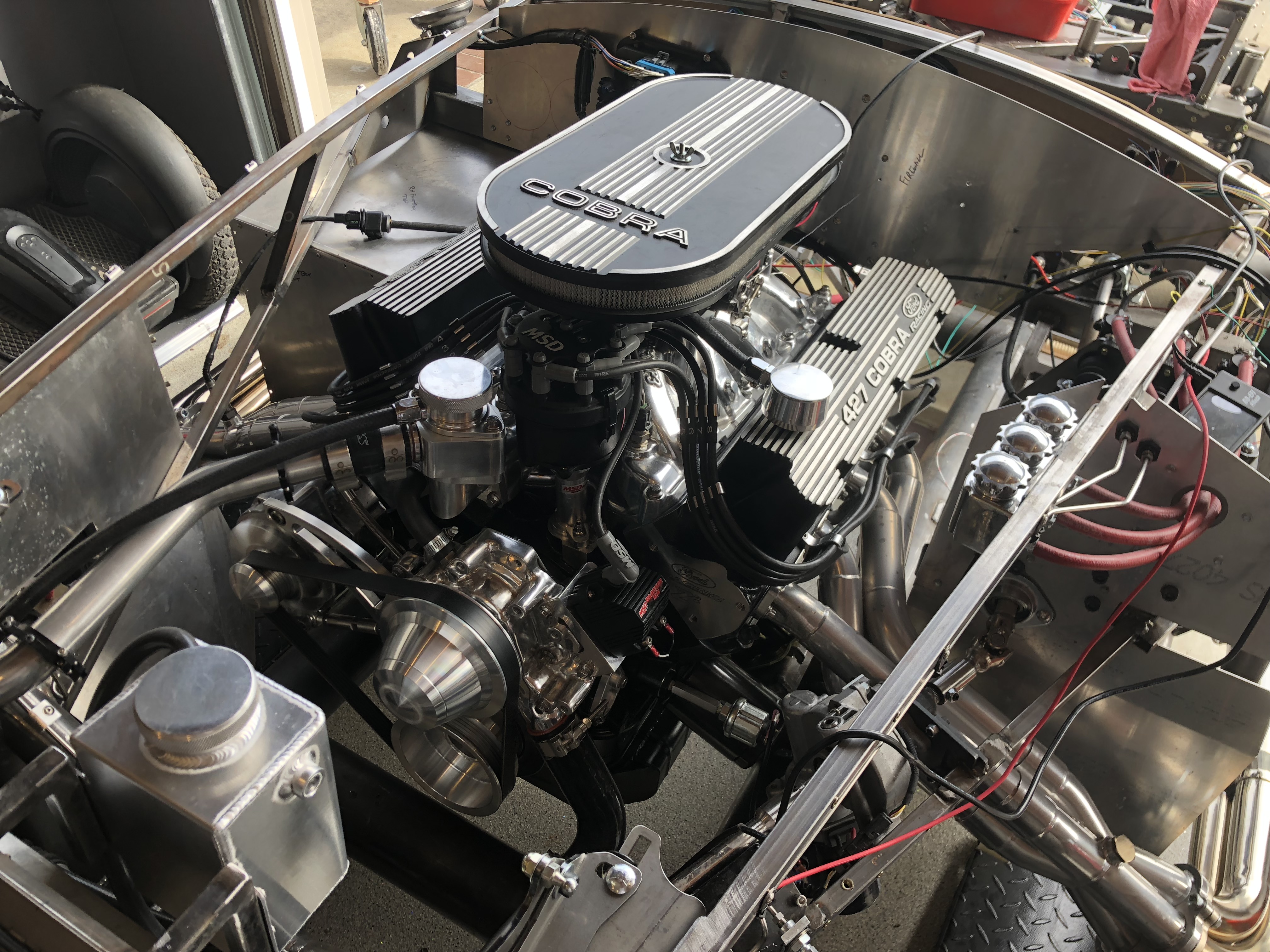
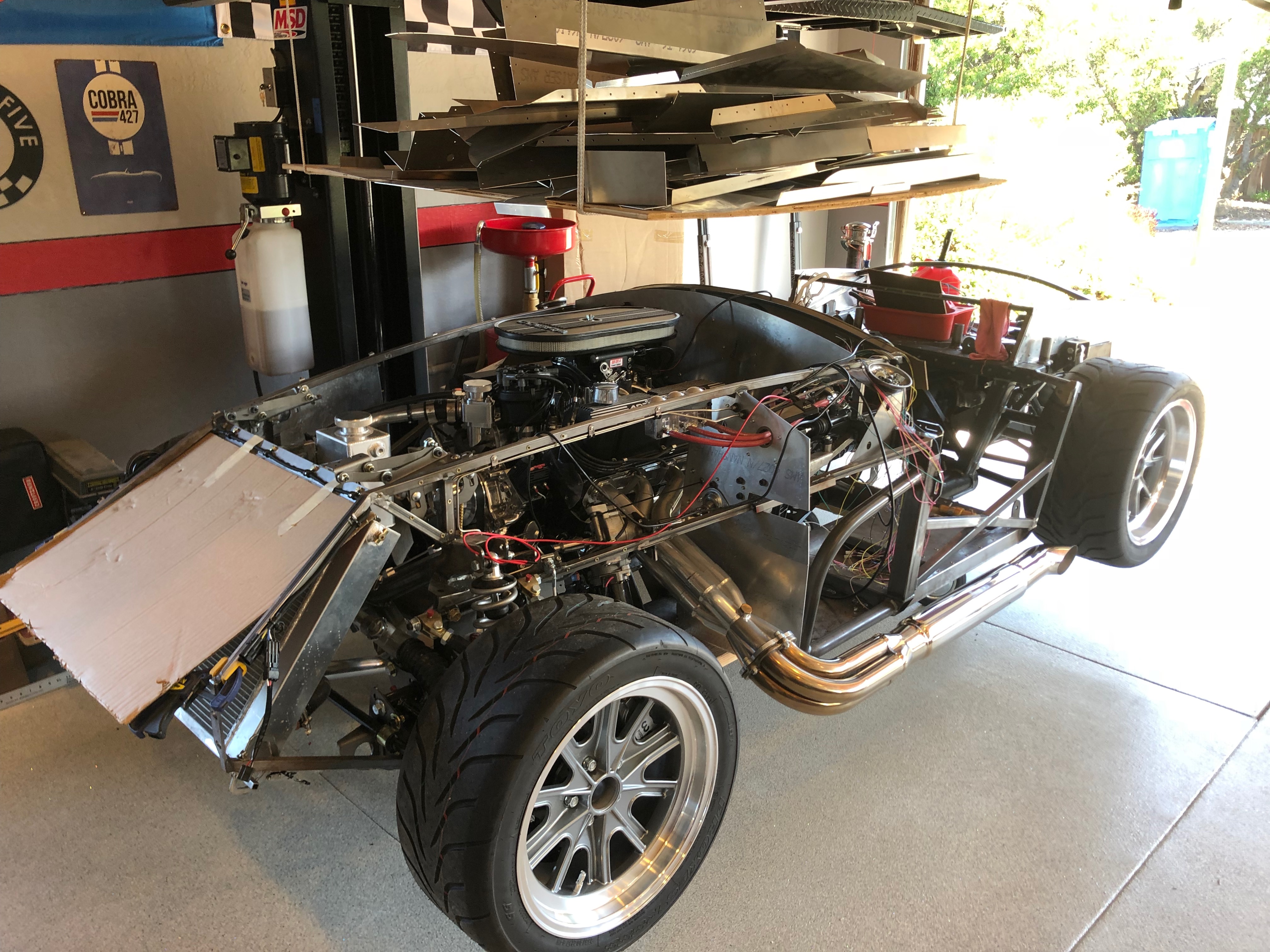
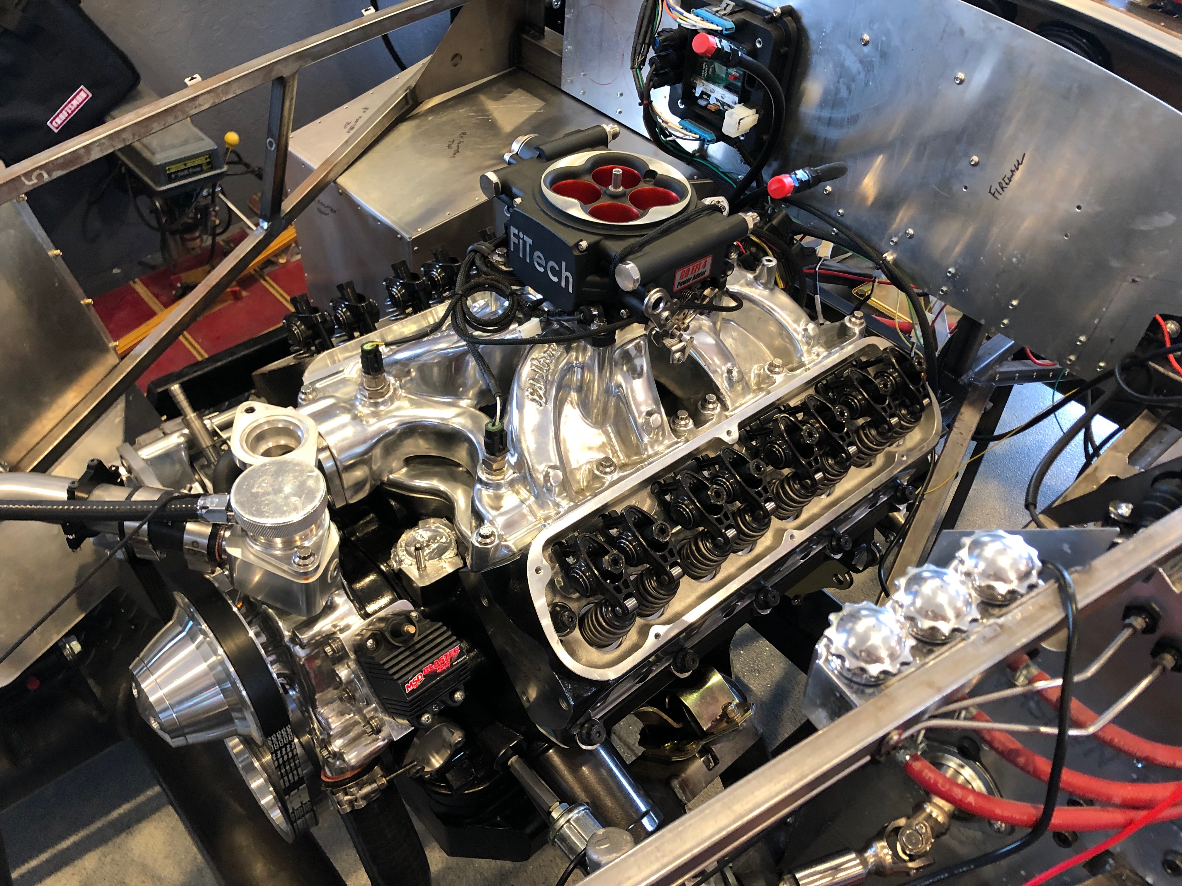
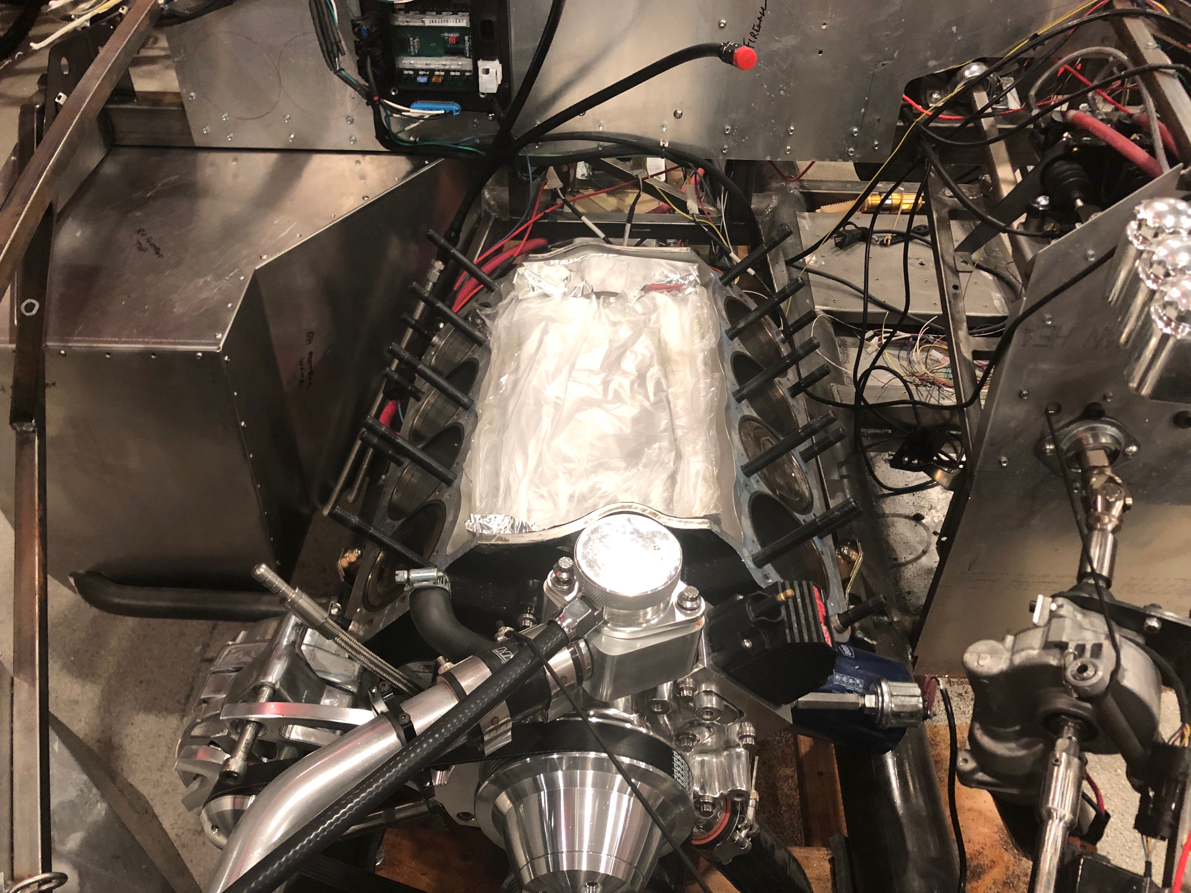
The other thing I did today was get the engine running again. It’s been quite awhile since it ran, so I disconnected the ignition coil and cranked until I had oil pressure. When I reconnected the ignition coil, it fired right up and ran great. I let it run for a bit to warm up and then revved it for a bit. The FiTech still doesn’t manage the fuel properly when reducing throttle after revving it, so it tends to die. I’ll need to dig into the config to see how to address this.

Reinstalled Firewall and Throttle Linkage

It seems like it’s been forever since I worked on the car, but home remodels and work have gotten in the way. The garage is finally back to a reasonable shape where I can work on the car though, so I pulled it out from under the lift and picked up where I left off.

I drilled and added rivnuts to the 2″ square cross tube every where I could reach, but the engine is in the way for all of the holes through the center. I’ll have to install those rivnuts after the engine is removed for chassis finishing.

I reinstalled the firewall and then installed the two rod end bearings that support the throttle shaft, then installed the throttle arms and connected the linkage. The throttle arm that connects to the engine is sitting at an unusual angle, but this is intentional. When we first start driving the car, I want to limit the throttle travel since this engine is such a beast. I set up the throttle linkage to only give us about 1/2 throttle to start with and I can adjust this over time as we get used to driving it.

Finished Throttle Linkage

I pulled out the accelerator pedal and drilled and tapped the upper arm for the 1/4-28 stud on the rod end bearing. Since there is a pedal box support that’s partly in the way, I installed the rod end bearing on the left side of the upper arm.

Unfortunately, that didn’t move the linkage far enough to the left to clear the pedal box support completely, so I also decided to slide the pivot shaft to the left a bit to increase the clearance. The pivot shaft now just sits flush with the right edge of the inner rod end bearing on the firewall.

To prevent the shaft from moving either direction, I installed the other shaft collar on the other side of the outer rod end bearing on the firewall.

This moved the pivot shaft and outer linkage an additional 3/8″ to the left. It’s pretty close to the steering shaft now, but still has plenty of clearance.

The linkage from the accelerator pedal upper arm to the pivot shaft arm now clears the pedal box support. It’s still pretty tight, so I may relieve the support slightly to prevent any touching, but at least I don’t need to remove a lot of material now to provide this clearance.

Started Installing Mechanical Throttle Linkage

I started installing the throttle linkage tonight. One disadvantage to installing the linkage directly to the 2″x2″ tubing is that it causes the linkage to sit at an angle. I tried installing it to the lower portion of the throttle arm which changes the throttle action from pull-to-increase to a push-to-increase, but the geometry made it nearly impossible to hit full throttle. By installing it to the upper portion of the throttle arm with a the pull-to-increase throttle action, it’s easy to move it through the full throttle range.

I installed two 3/8″ rivnuts into the 2″x2″ square chassis tubing. The first one is almost directly behind the throttle arm so that the linkage is parallel with the valve covers. I used some 2″ pieces of 3/8″-24 stainless all-thread to attach the rod end bearings to the tubing. The throttle linkage is connected to a throttle arm from Speedway that attaches to a 12″ pieces of stainless rod.

The other end of the stainless rod goes through the second rod end bearings that’s installed inside the driver’s footbox. There is a second Speedway throttle arm here with another linkage to the accelerator pedal.

I haven’t hooked up the forward end yet because the throttle pedal is drilled for #10 screws and I inadvertently ordered a rod end linkage with a 1/4″ stud. I might try drilling this out before ordering more parts.

Engine is Fixed!!!

My dad stopped by again this morning and we wrapped up the engine assembly. We ran the oil pump for about three minutes with a drill and spun the motor over a few times with the starter (without plugs) to make sure oil was nicely distributed throughout the engine.

The moment of truth arrived and we fired up the motor. Success!!! The motor sounds fantastic. Nice and smooth, and no knocking!

We kept the exhaust pipes outside of the garage to limit the exhaust inside. We pushed the RPM up to about 2,500 and let it run for about 30 minutes to help seat the rings.

After shutting down, we pulled the car back into the garage and put the car back on the dolly. Since we’re still in the middle of our remodel, we likely won’t make much progress on the car over the next few months, but I’m incredibly pleased that this is behind us!

Installed New Piston

My dad and I stopped by Dino’s shop this morning to have him balance our new piston and rod. While our piston was lighter than the old one, we lucked out and the new rod was slightly heavier on the small end. There’s still a small imbalance, but Dino said that it’s more important that the rotating mases are balanced than the reciprocating masses. He also loaned us his tapering ring compressor which makes piston installation far easier than with the traditional ring compressor

We got back to the house and made quick work of getting the piston into the block and installing the bearing cap. We turned the motor over a couple of times to make sure everything was moving smoothly.

We installed the newly painted oil pan, then installed and torqued the heads. I hadn’t yet adjusted the guide plates on the new cylinder head, so we spent a bit of time ensuring that all of the rocker rollers were nicely centered over the valve stems. Finally, we installed the intake manifold and cleaned up the sealant. We can’t run the motor until that sets, so that was a good time to stop for the day.

Painted Oil Pan and New Piston Weight

I cleaned the oil pan and painted four coats of the same Eastwood high-temperature ceramic engine paint that I’ve used on the rest of the engine. I put on some extra coats here because this is likely to take more abuse from road debris than the block or heads.

I received the new piston from Ford Racing (on the right). Unfortunately, it’s 9 grams lighter than the piston it’s replacing. We’ve been told that we need to get the rod/piston assembly within 2 grams, but we’ve also heard that it’s important to get each component as close as possible as well. We’ll check with Dino about whether this will work or we need to order a replacement.

Pulled #6 Piston

We put the Cobra on the lift and dropped the oil pan. After removing the connecting rod bolts, we removed the bottom of the connecting rod and pushed the piston out of the top of the cylinder.

It’s pretty clear that the piston was more damaged that it appeared from the top. This is the bottom edge and it’s pretty well worn above the compression ring. It’s also pretty scored on the skirt. Worse though, both compression rings were pinched in the groooves.

This is the top edge of the piston. You can see wear above the compression rings and scoring on the skirt. The compression rings are also pinched on this side.

In the area the pistons are worn, there is some polishing of the cylinder wall. You can’t feel this with your fingers, so it’s just some microscopic surface polishing. We’ll need to add the cross-hatching back, but that should be pretty straightforward.

It’s pretty hard to see in this picture, but the lower side of the cylinder has similar polishing, but you can slightly feel the polished area on this side. There are no grooves and I think what you can feel is well less that 0.001″.

We dropped by Dino’s shop to have him examine the piston and connecting rod. He showed us how to remove the piston and checked the connecting rod for damage. He suggested we use some 400-600 grit sandpapaer to add the crosshatching pattern back to the cylinder wall. I protected the lower end of the engine as well as I could with aluminum foil and masking tape, then used some 400 grit sandpaper soaked in solvent to add the crosshatch pattern back. I made some good progress on the lower side, but I can still feel the polishing area slightly.

Painted Cylinder Head Engraving

After thoroughly cleaning the engravings with some solvent and a toothbrush, I put some of the of the engine paint over the engravings until I couldn’t see them. After letting it set up for a couple of hours, I used a solvent-soaked q-tip to remove most of the excess paint. I didn’t want do too much at this point since the paint is still soft.

After letting the paint cure overnight, I used more solvent-soaked q-tips to remove the rest of the excess paint. This technique works wonderfully and the engraving really pops.

Pulled Remaining Head and Prepped Replacement

Even though we’re essentially certain the heads are fine, we still had one head with known damage from the nut going through the engine. It just turned out not to be on the side where he was adjusting the lifter. Since we had already ordered a replacement head, I could either return that or replace the damaged head. I decided to replace it.

I spent a couple of hours tearing down the right side of the motor tonight until it was at the same place as the left side.

I cleaned and masked the new head, then sprayed several coats of Eastwood’s high-temperature ceramic engine paint in gloss black.