Started Installing Mechanical Throttle Linkage

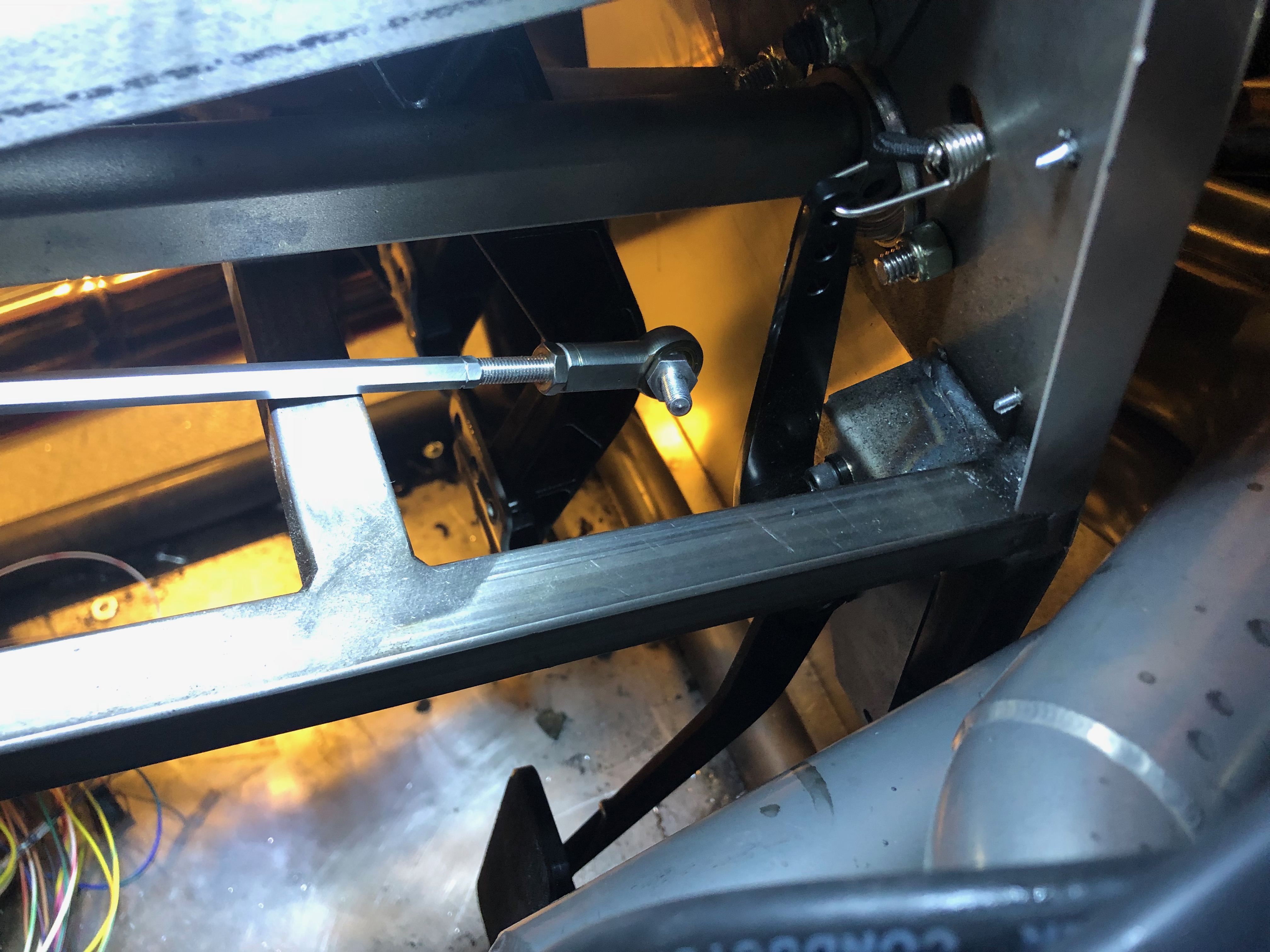
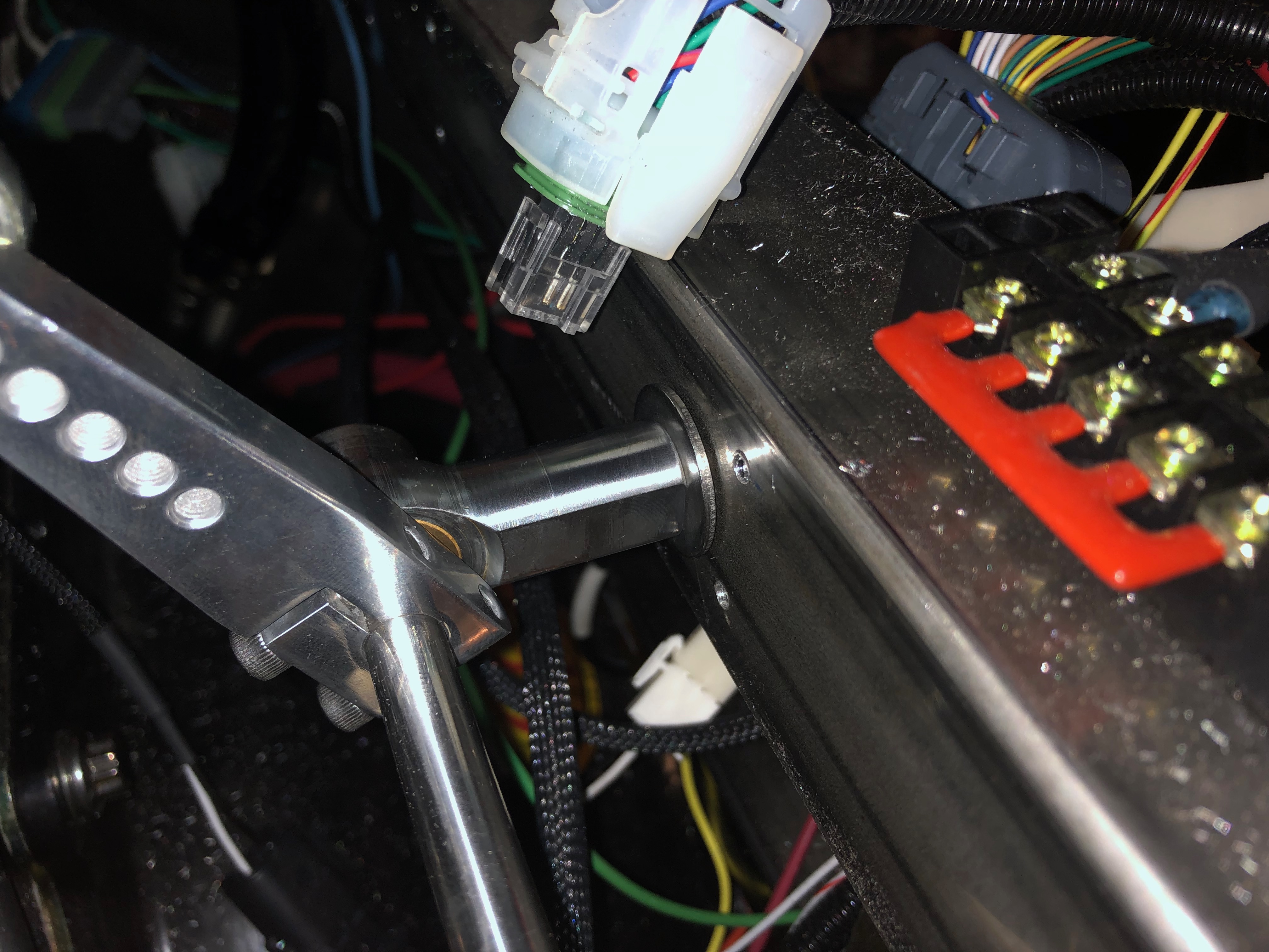
I started installing the throttle linkage tonight. One disadvantage to installing the linkage directly to the 2″x2″ tubing is that it causes the linkage to sit at an angle. I tried installing it to the lower portion of the throttle arm which changes the throttle action from pull-to-increase to a push-to-increase, but the geometry made it nearly impossible to hit full throttle. By installing it to the upper portion of the throttle arm with a the pull-to-increase throttle action, it’s easy to move it through the full throttle range.

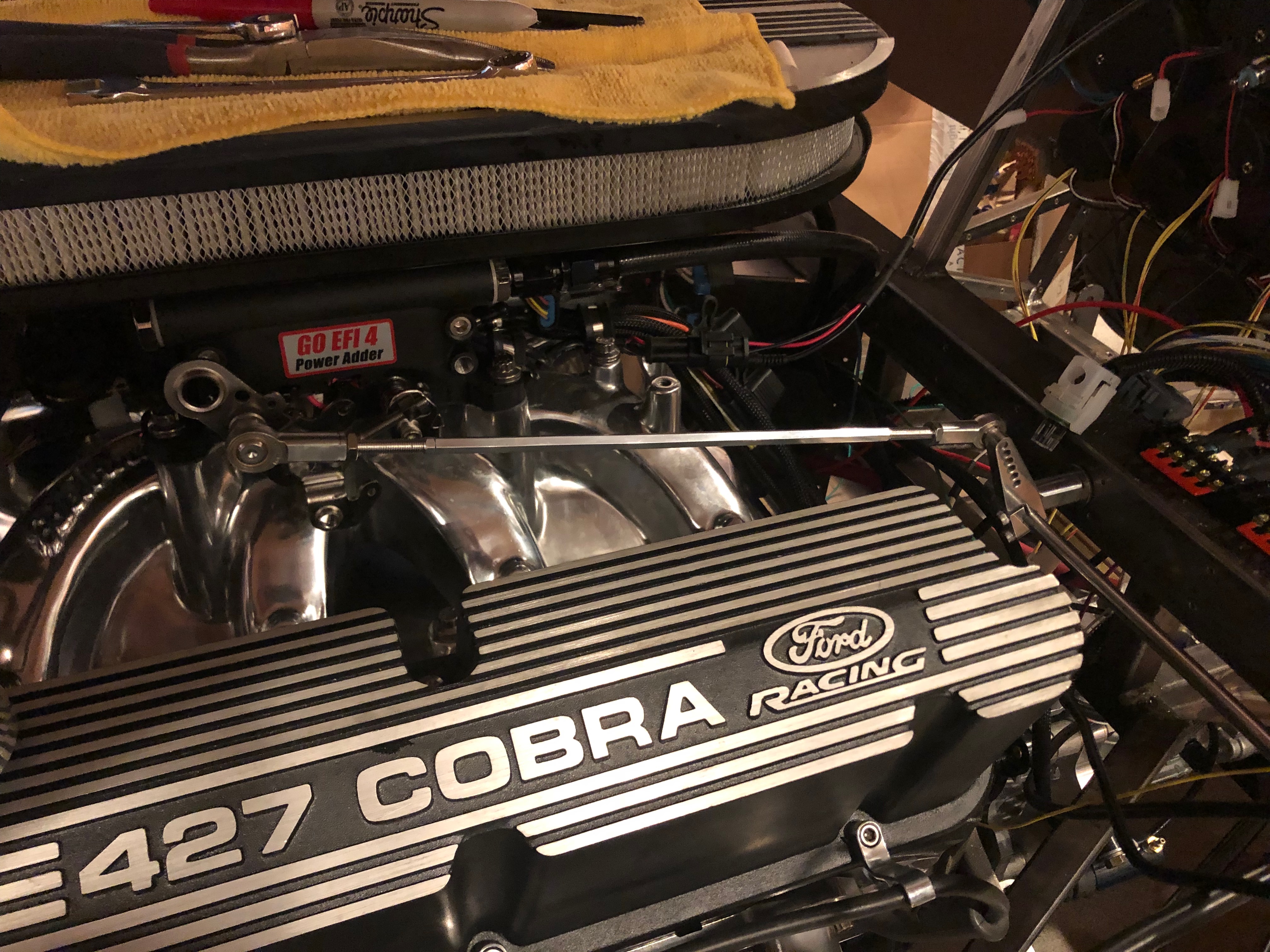
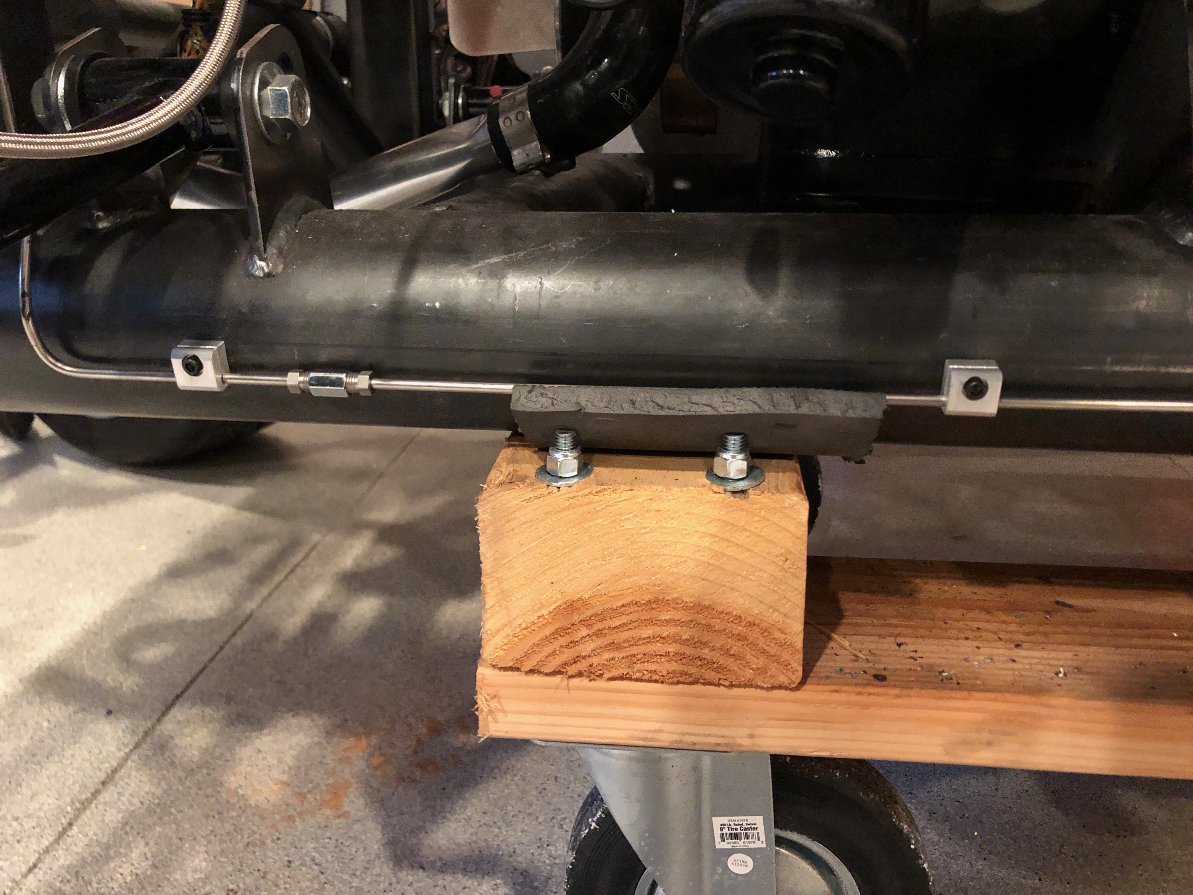
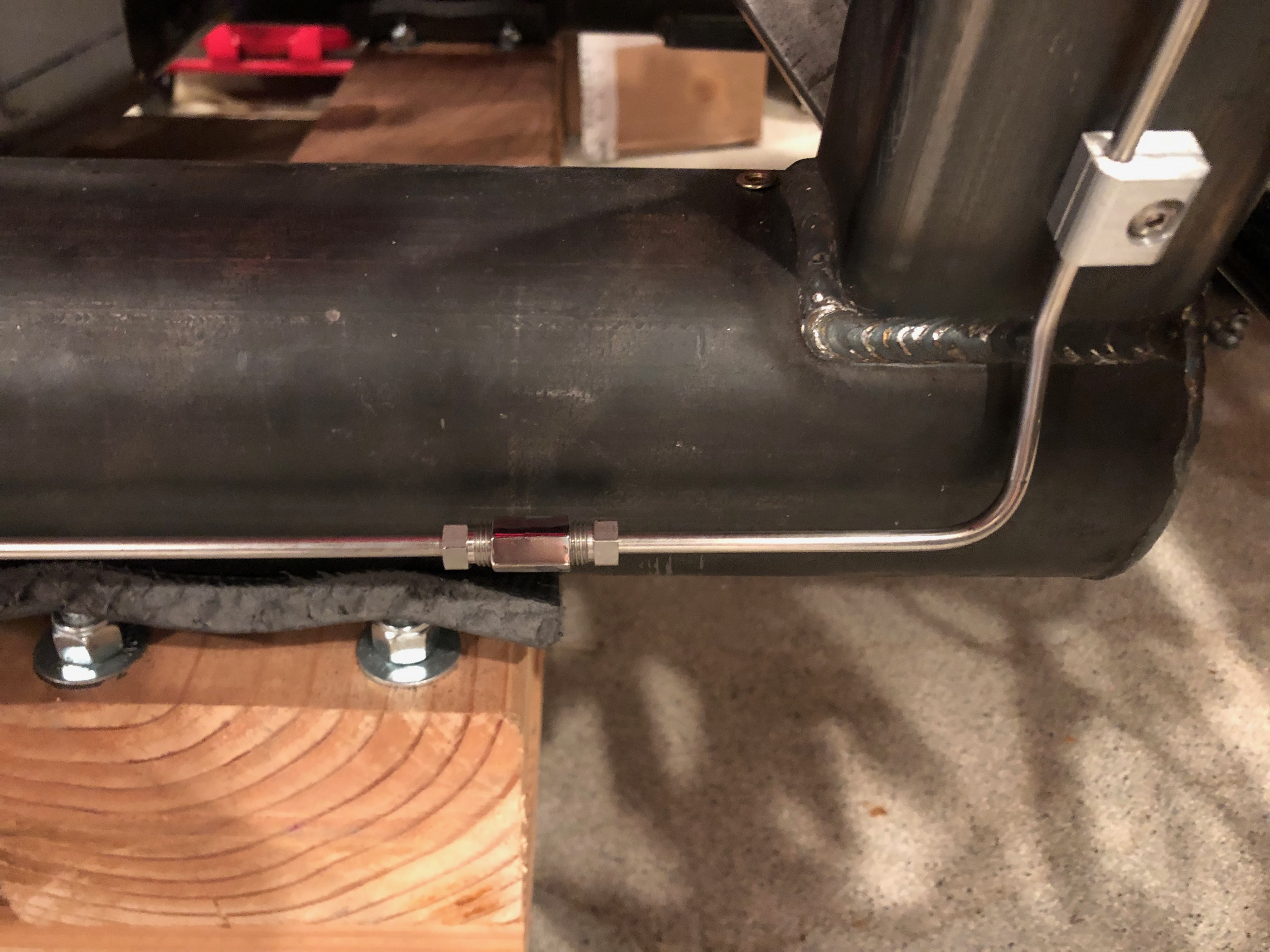
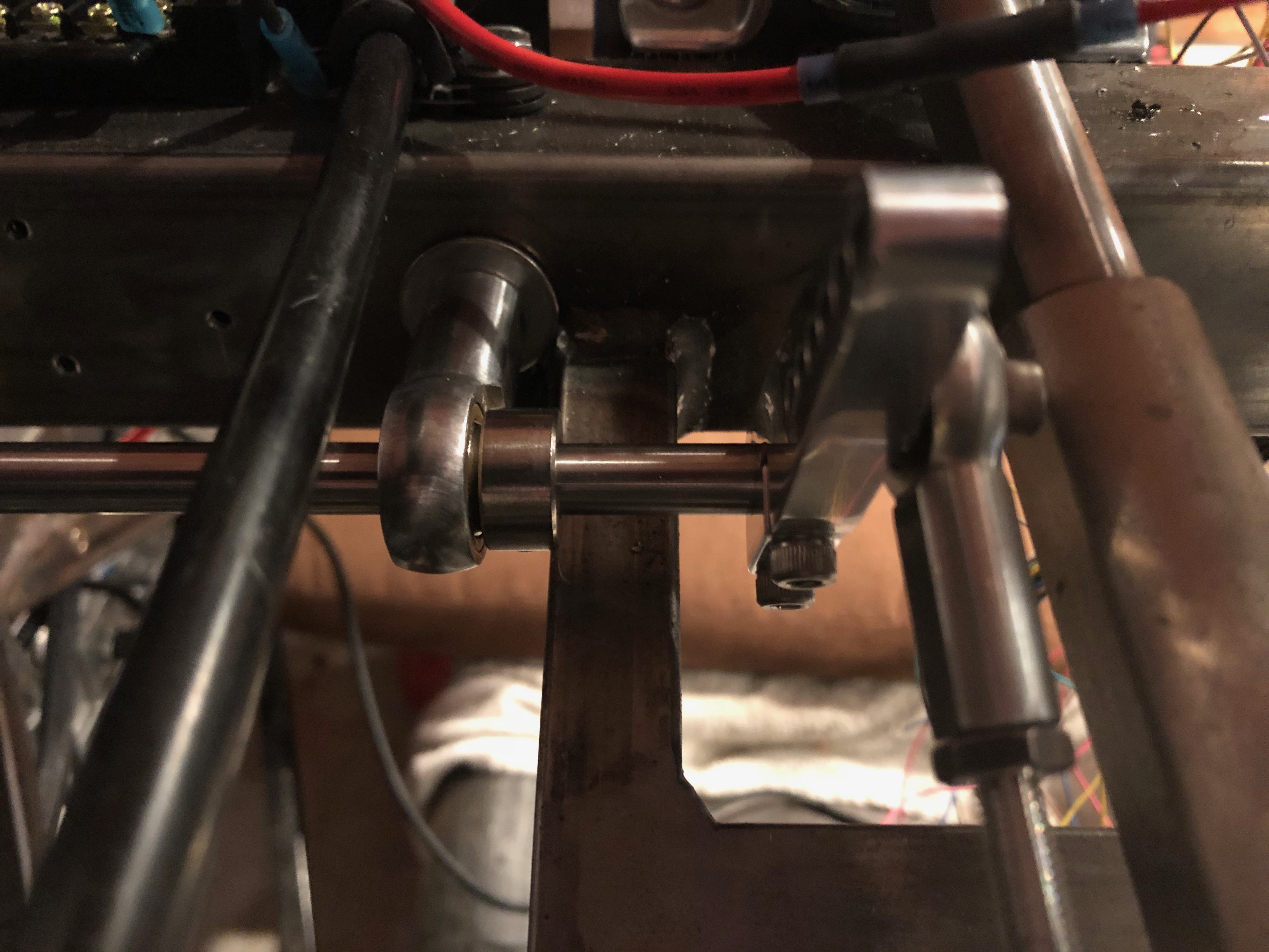
I installed two 3/8″ rivnuts into the 2″x2″ square chassis tubing. The first one is almost directly behind the throttle arm so that the linkage is parallel with the valve covers. I used some 2″ pieces of 3/8″-24 stainless all-thread to attach the rod end bearings to the tubing. The throttle linkage is connected to a throttle arm from Speedway that attaches to a 12″ pieces of stainless rod.

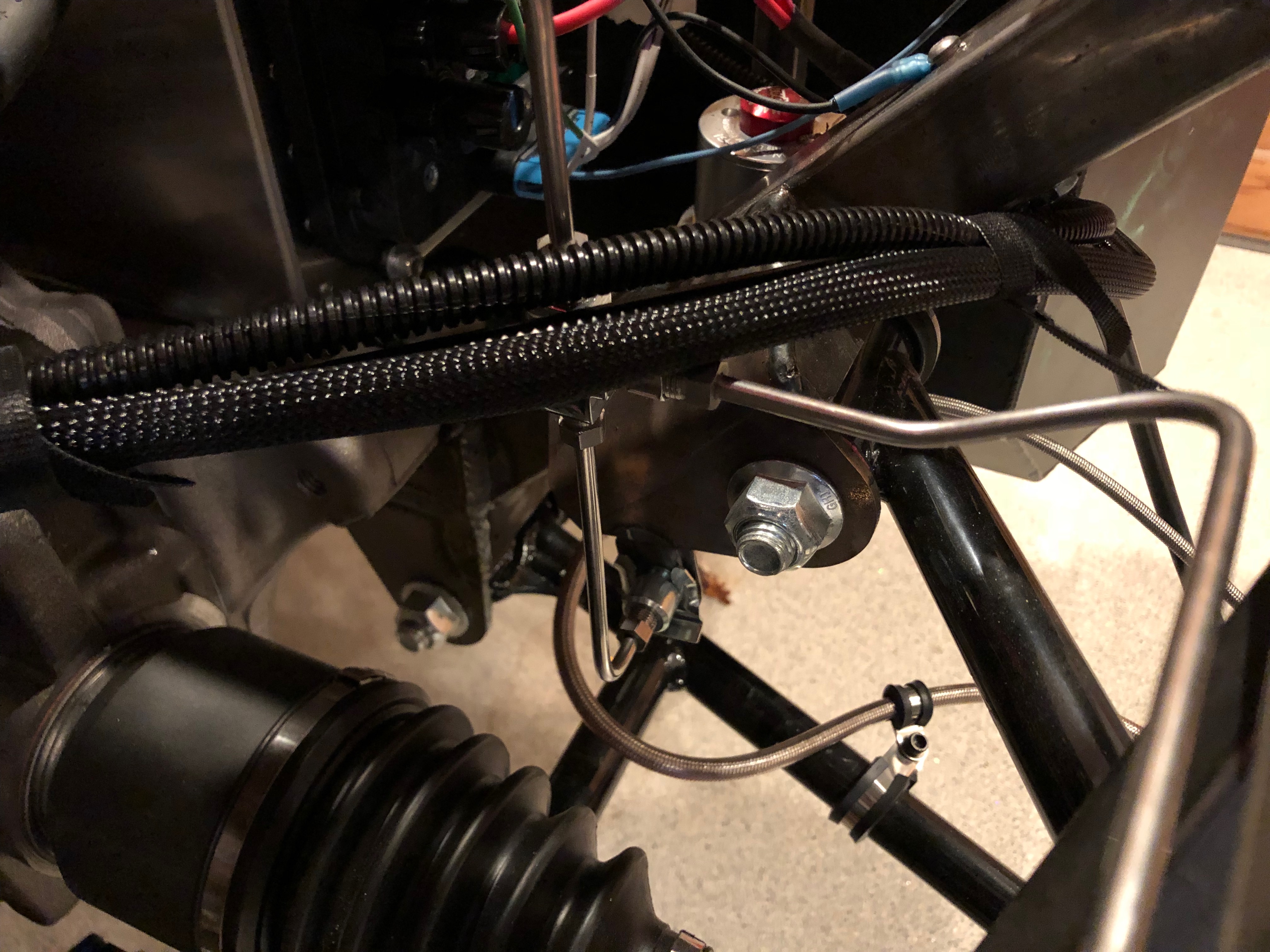
The other end of the stainless rod goes through the second rod end bearings that’s installed inside the driver’s footbox. There is a second Speedway throttle arm here with another linkage to the accelerator pedal.

I haven’t hooked up the forward end yet because the throttle pedal is drilled for #10 screws and I inadvertently ordered a rod end linkage with a 1/4″ stud. I might try drilling this out before ordering more parts.

Removed Firewall

I’m planning on installing a mechanical throttle linkage instead of using a throttle cable. There is a kit available, but plenty of people have fabricated their own. They typically install it to the firewall above the 2″x2″ square tubing, but that requires installing some firewall reinforcement that ties that area to the top of the square tubing. Unfortunately, I’ve already installed some electrical components in this area, so I decided to install it directly onto the 2″x2″ square tubing. To do that, I needed to get the firewall out of the way.

The firewall-to-chassis attachment is the only place on the chassis that I haven’t installed rivnuts, so I’ll do that as well while the firewall is out.

Wrapped Up Brake Line Installation

I laid out and installed all of the brake line supports for the long, straight run along the 4″ chassis tubing. There are four of the mounts with the curved back mounted directly the the 4″ chassis tube.

There are also a couple of mounts attached to the underside of the square tubing under the seat. I didn’t realize until after I took this picture that I had intended to install the spiral brake line guard before flaring the ends. I’ll have to see if the tubing is long enough to remove one of the flares and install the guard. I’d really hate to have to remake the brake line.

After torquing all of the fittings, I filled the fluid reservoirs and started trying to bleed the brakes. I still have more work to do to get all the air out of the system.