Steering Linkage, Chassis Mods and Timing Pointer

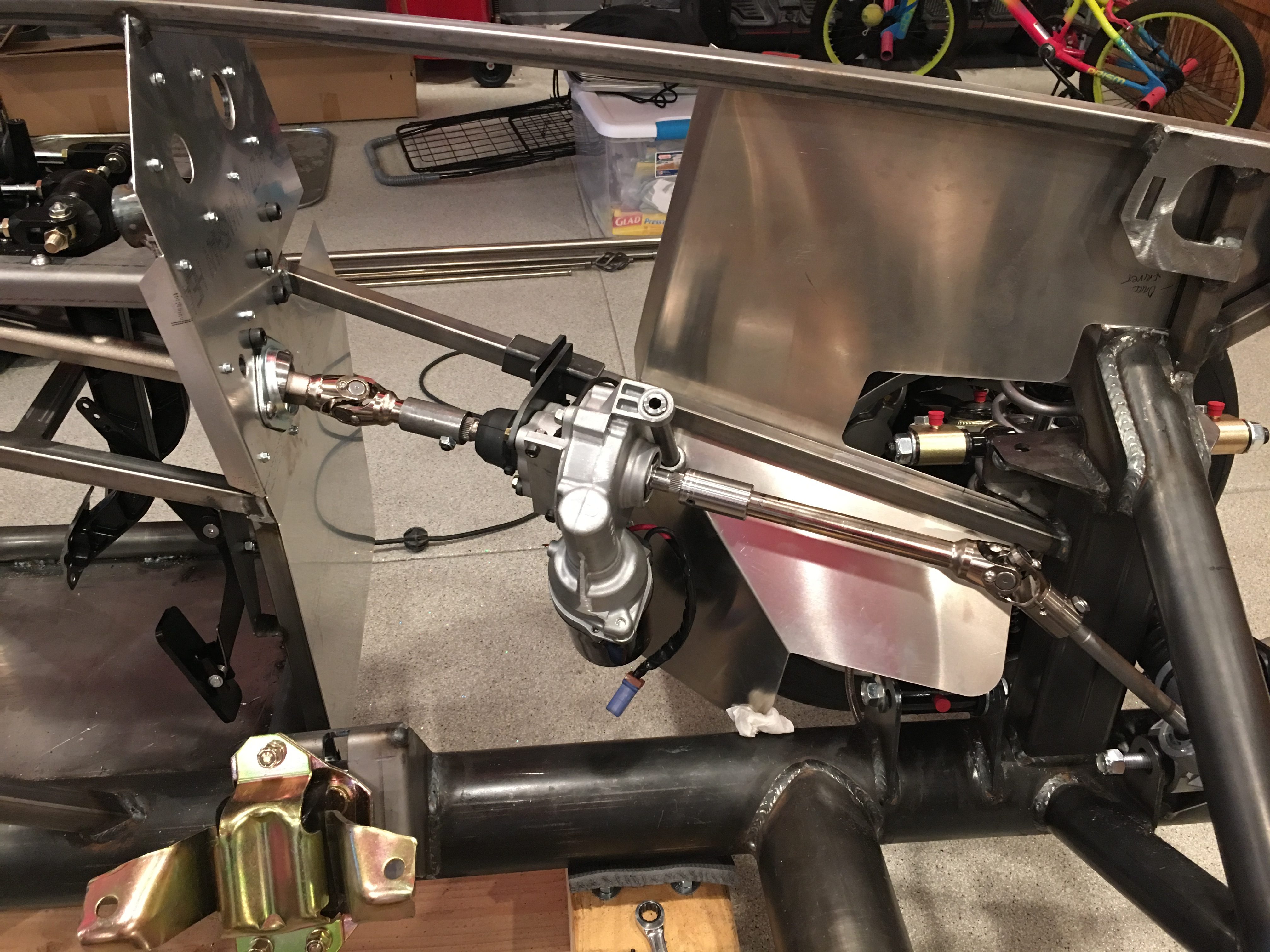
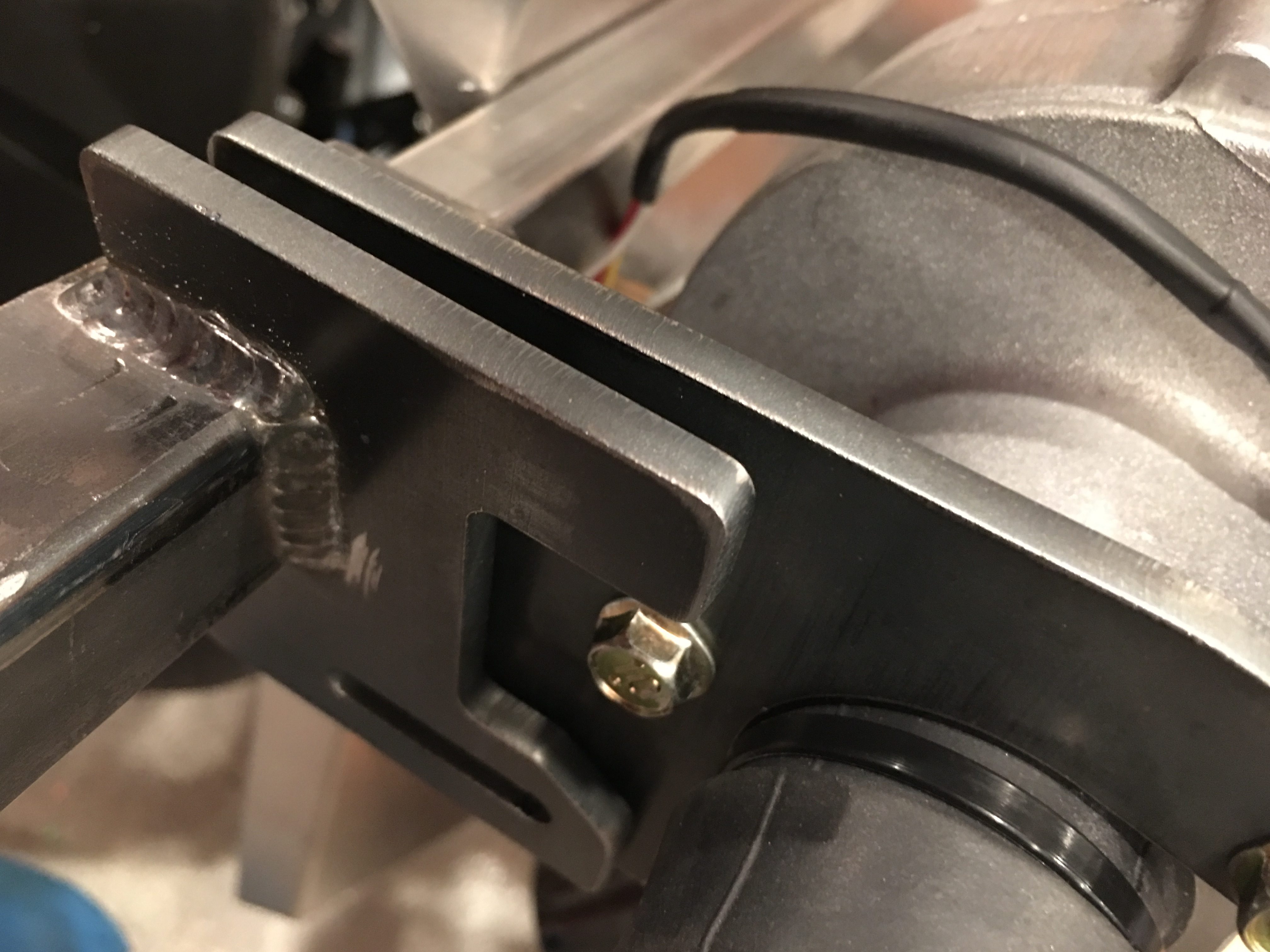
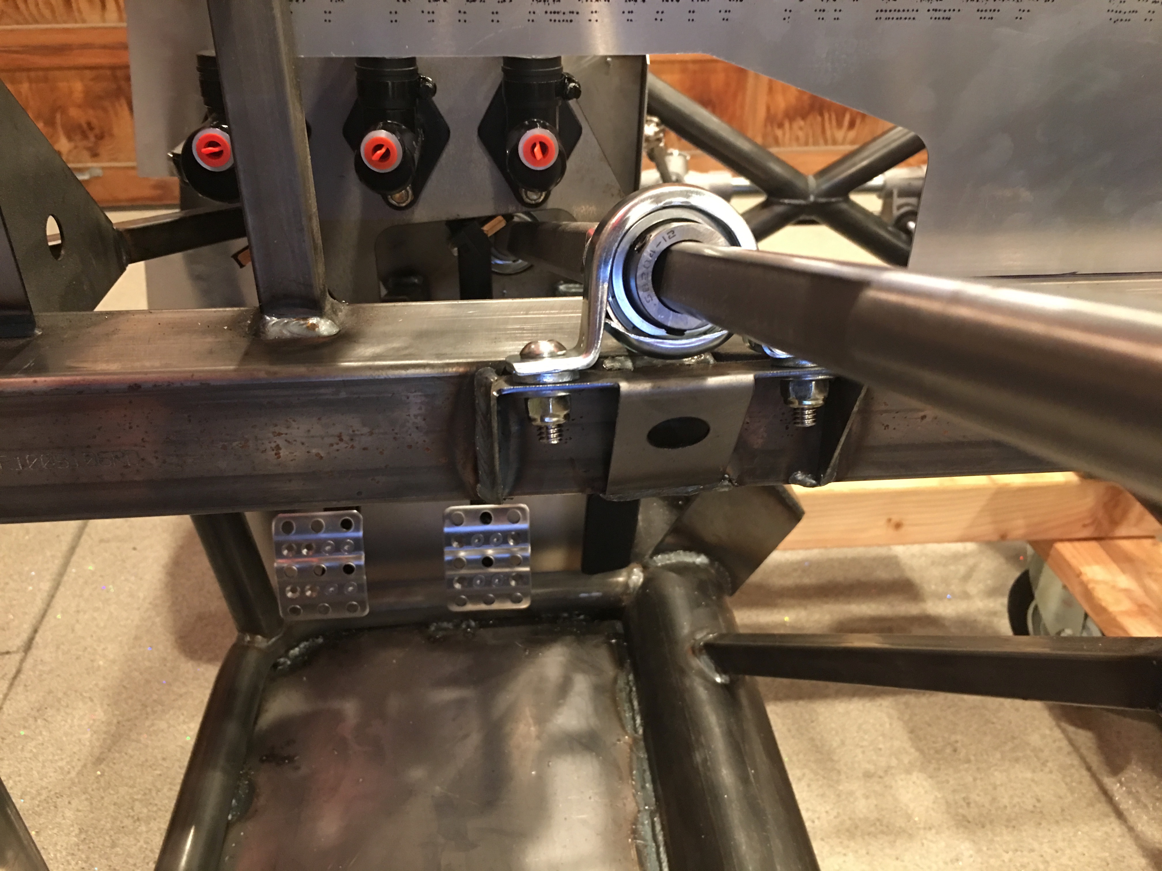
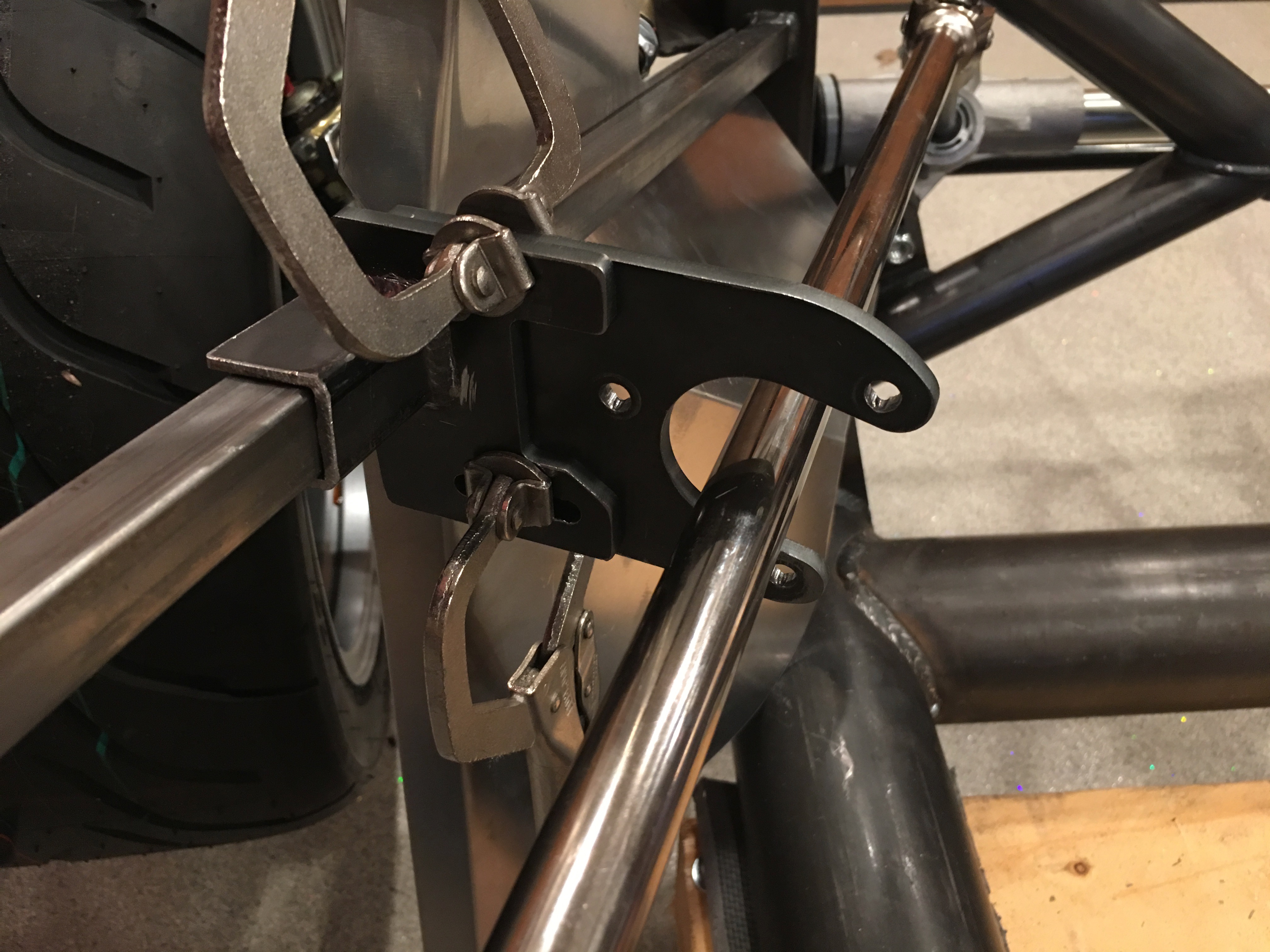
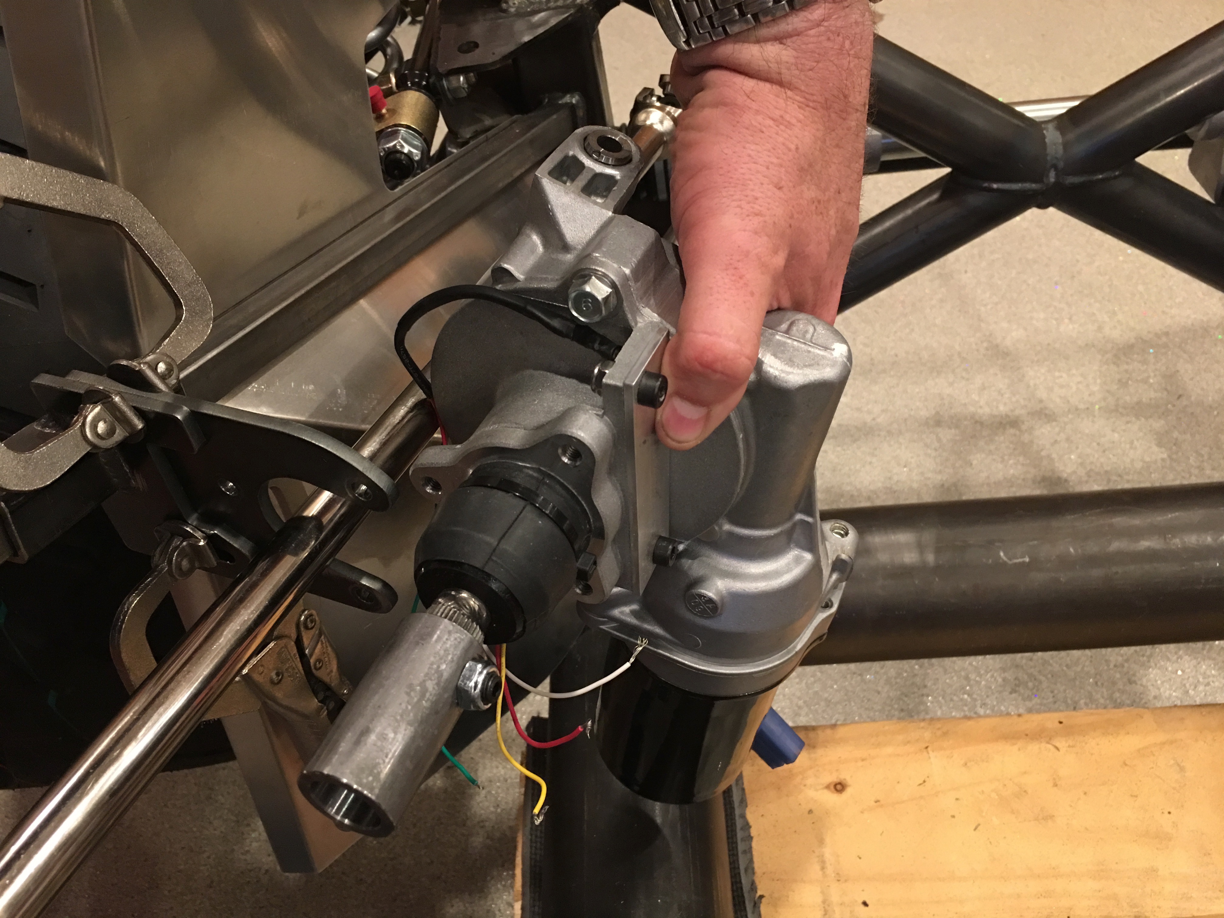
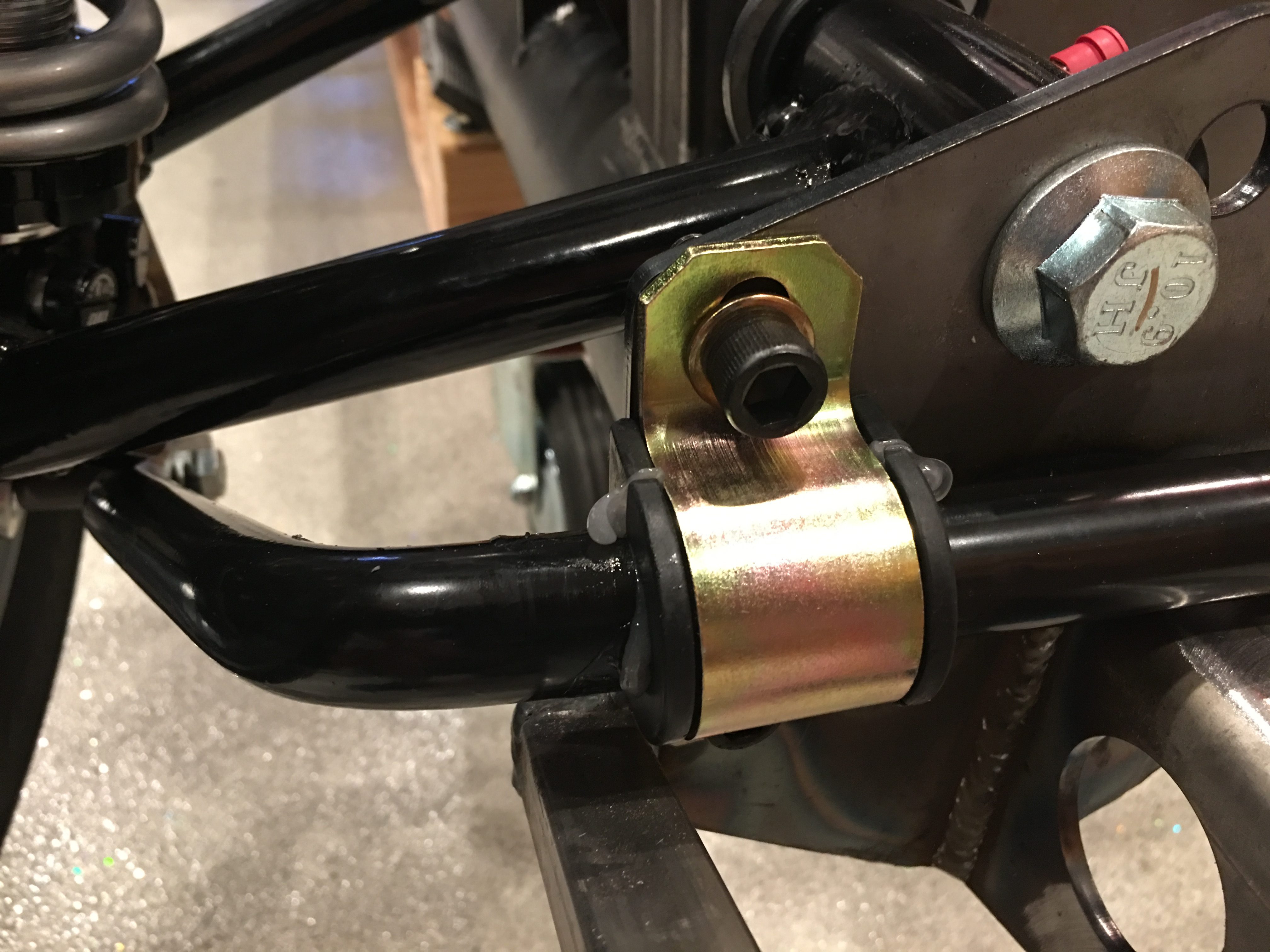
I installed the EPS brackets and tacked the two pieces of the bracket together and tacked it to the chassis. I’ll finish welding this after pulling the steering linkage off and unscrewing the aluminum F panel.

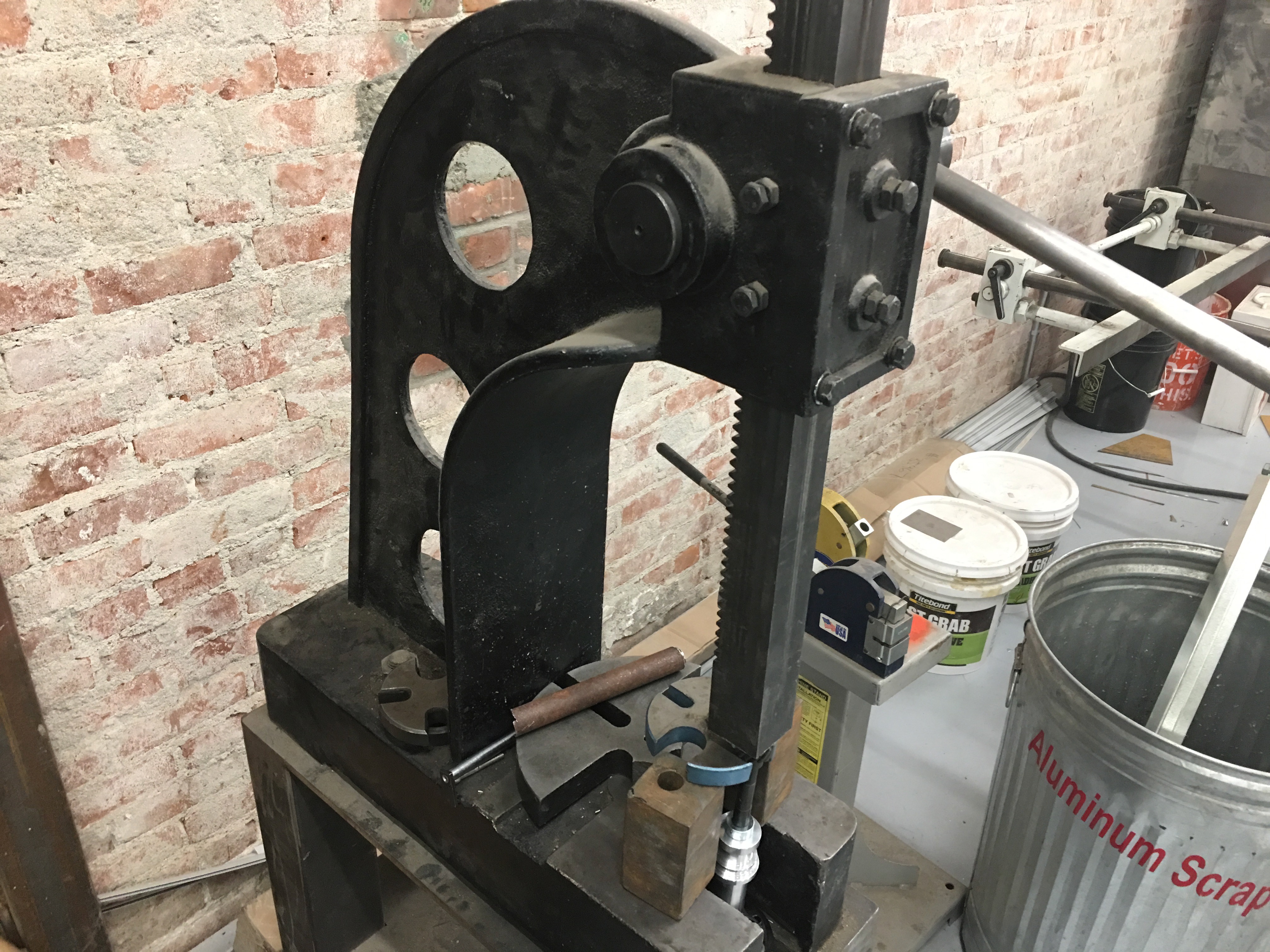
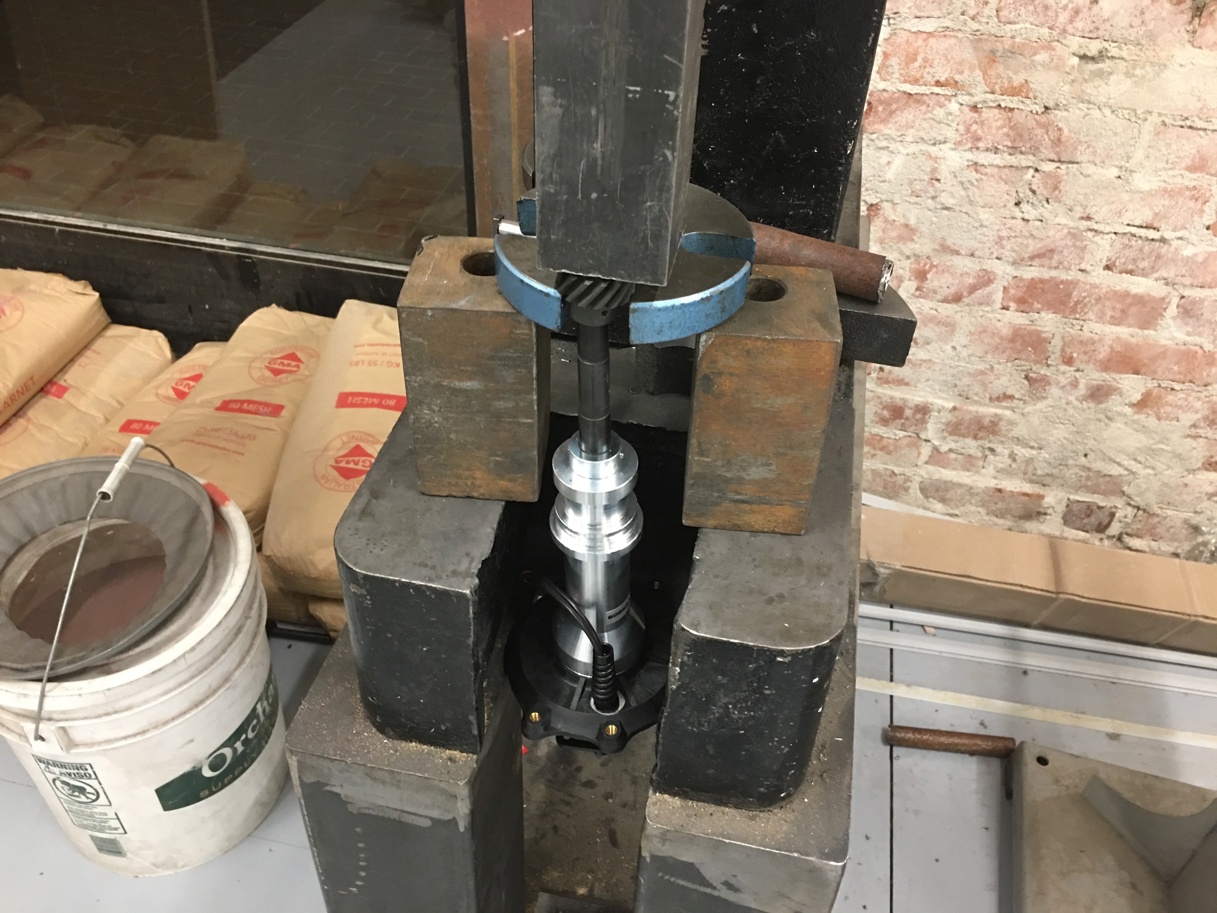
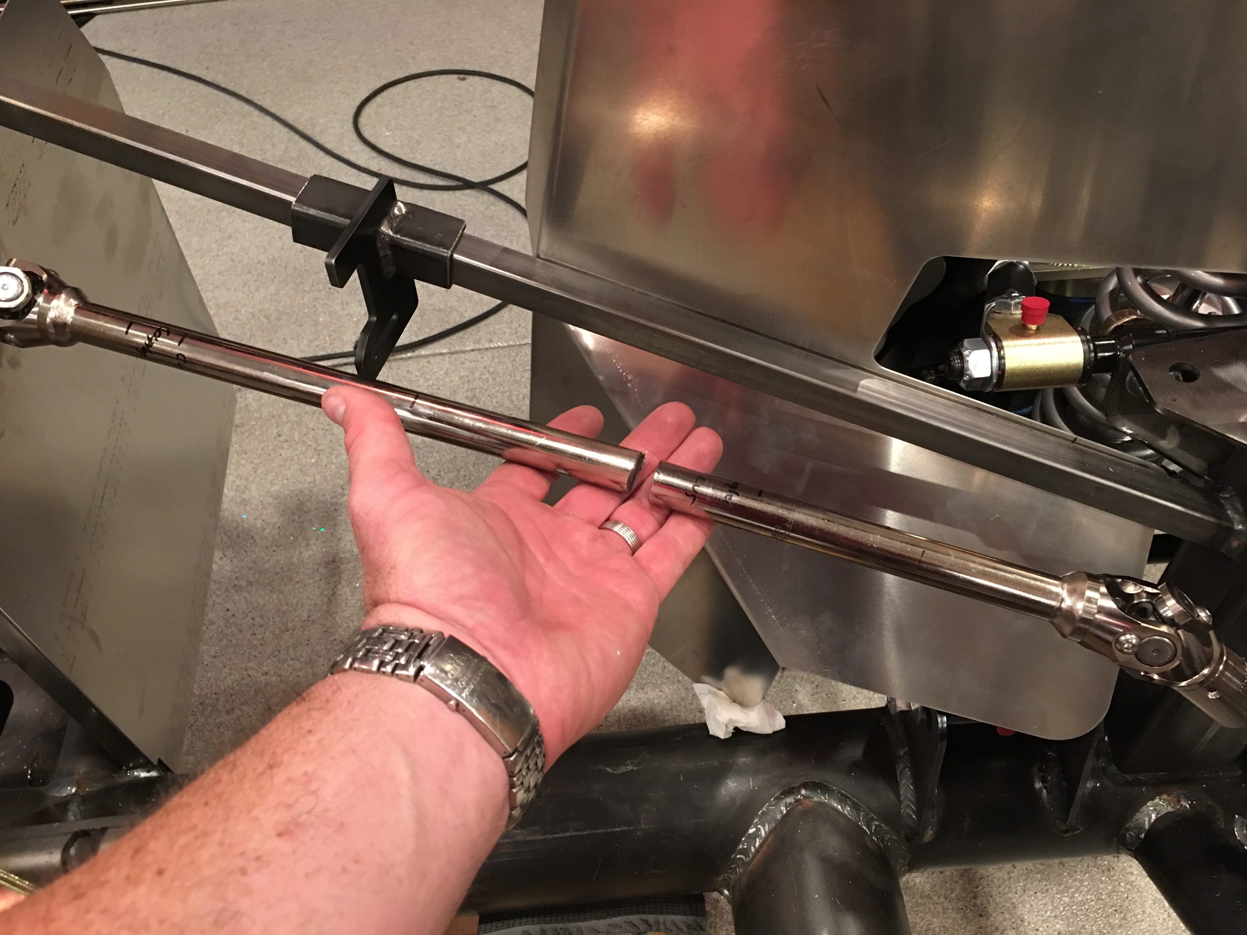
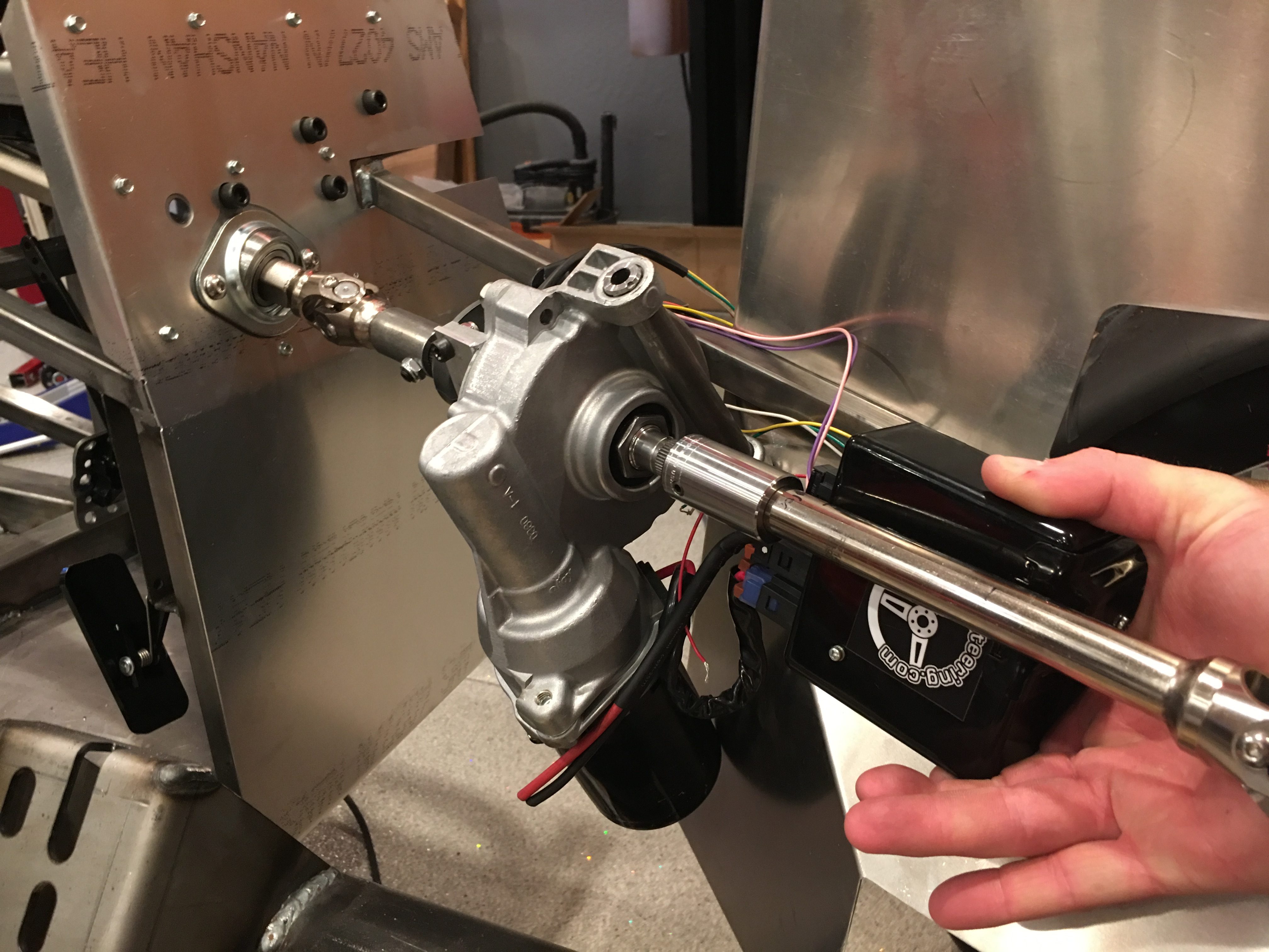
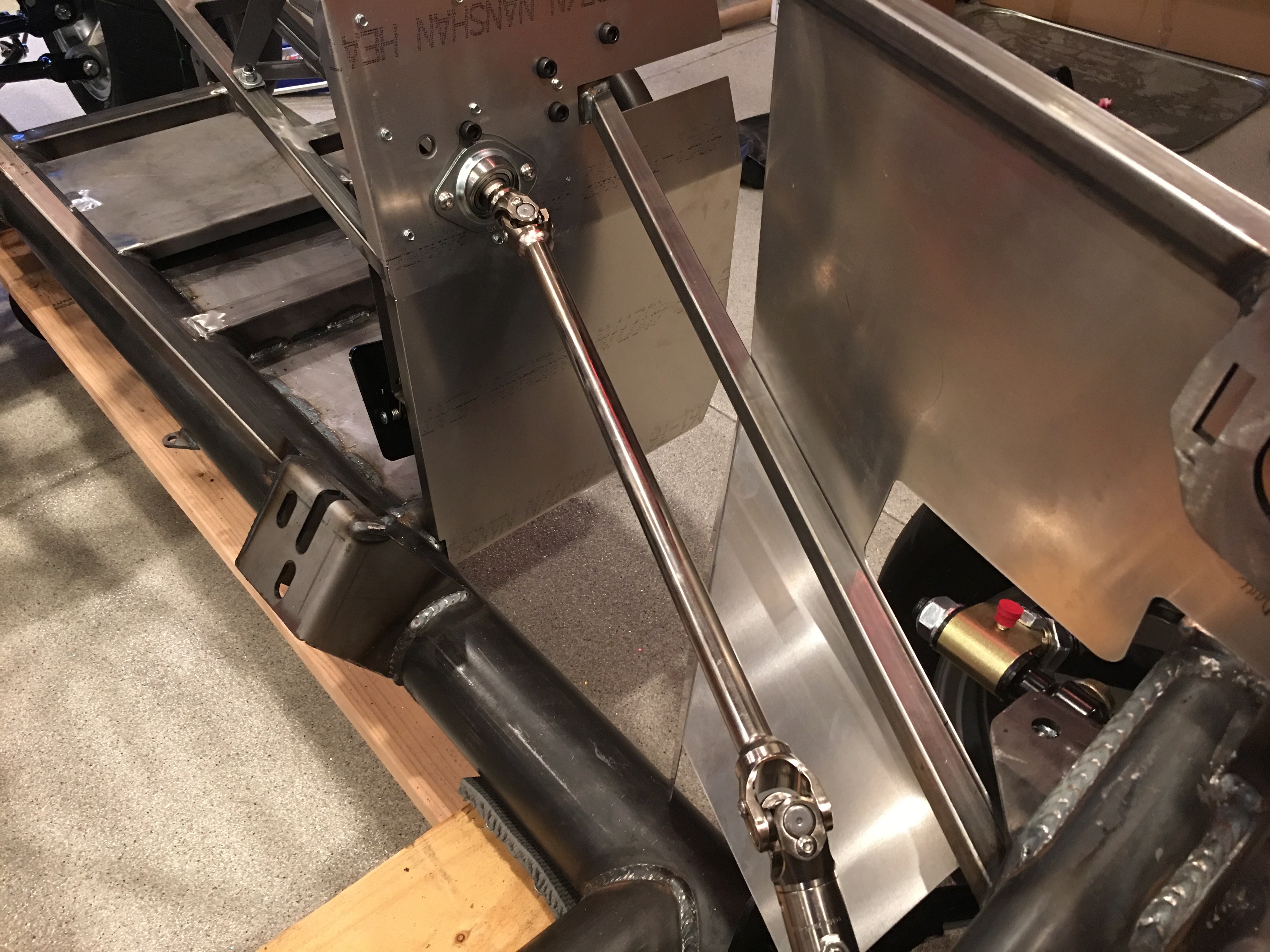
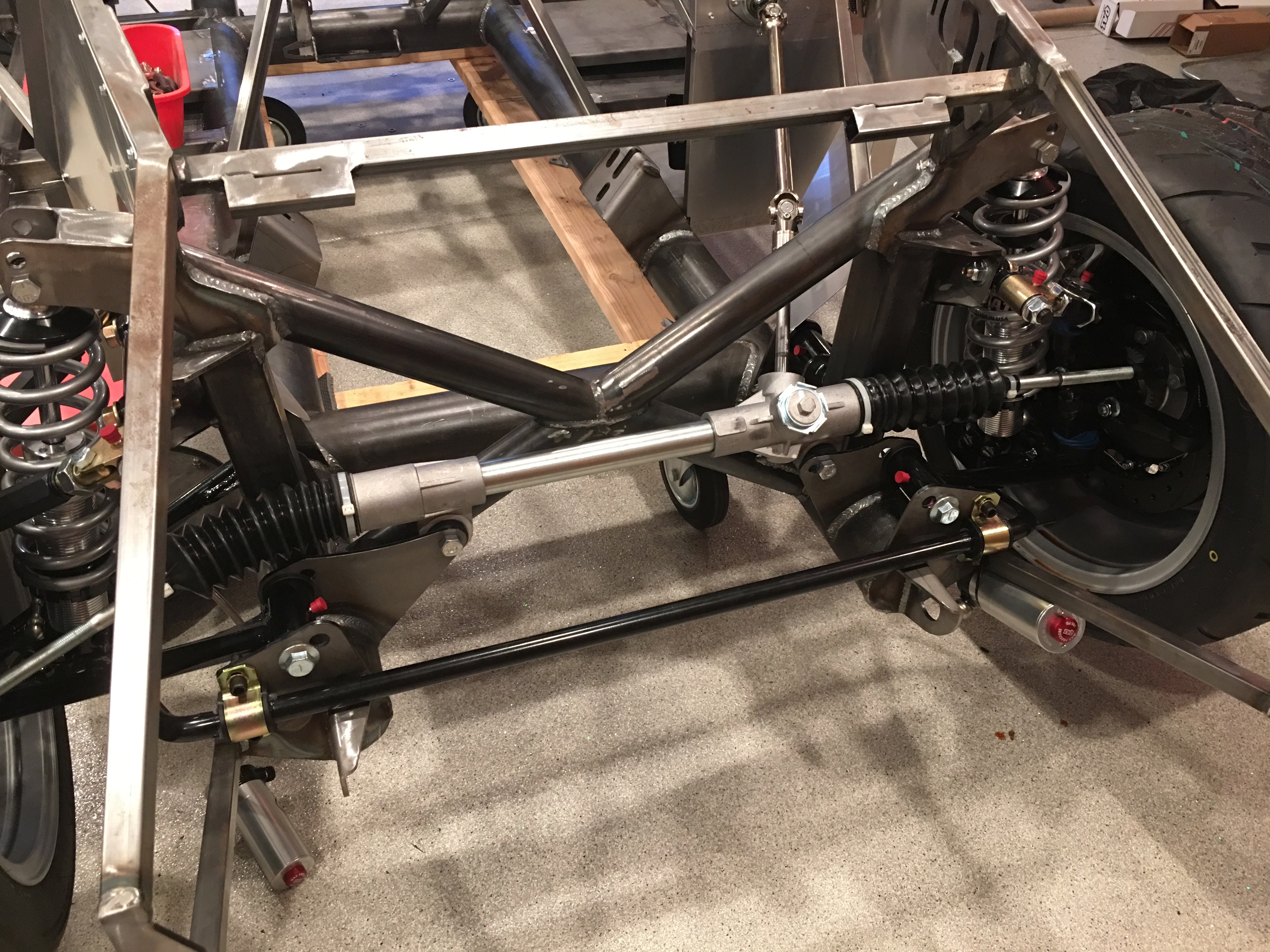
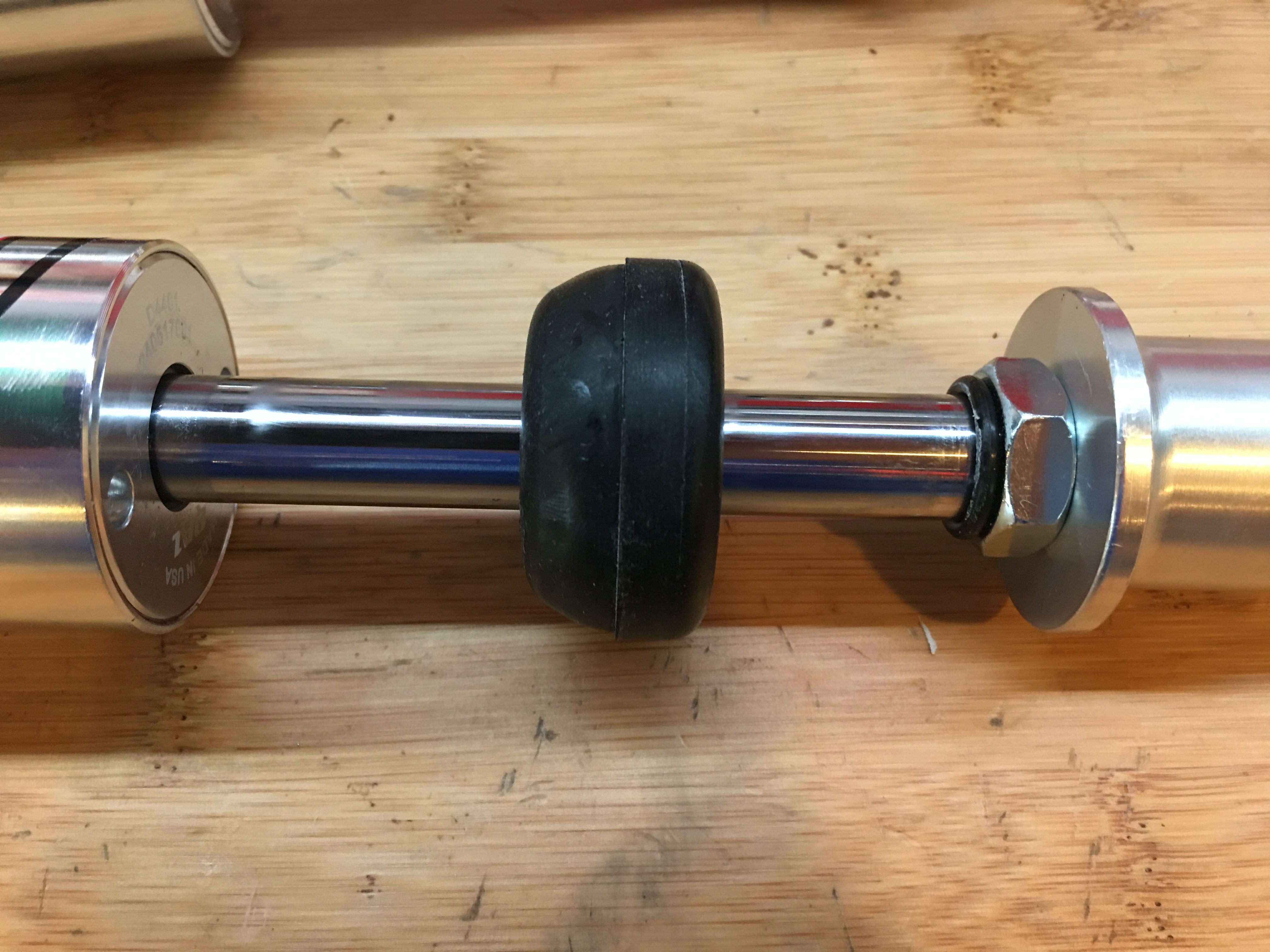
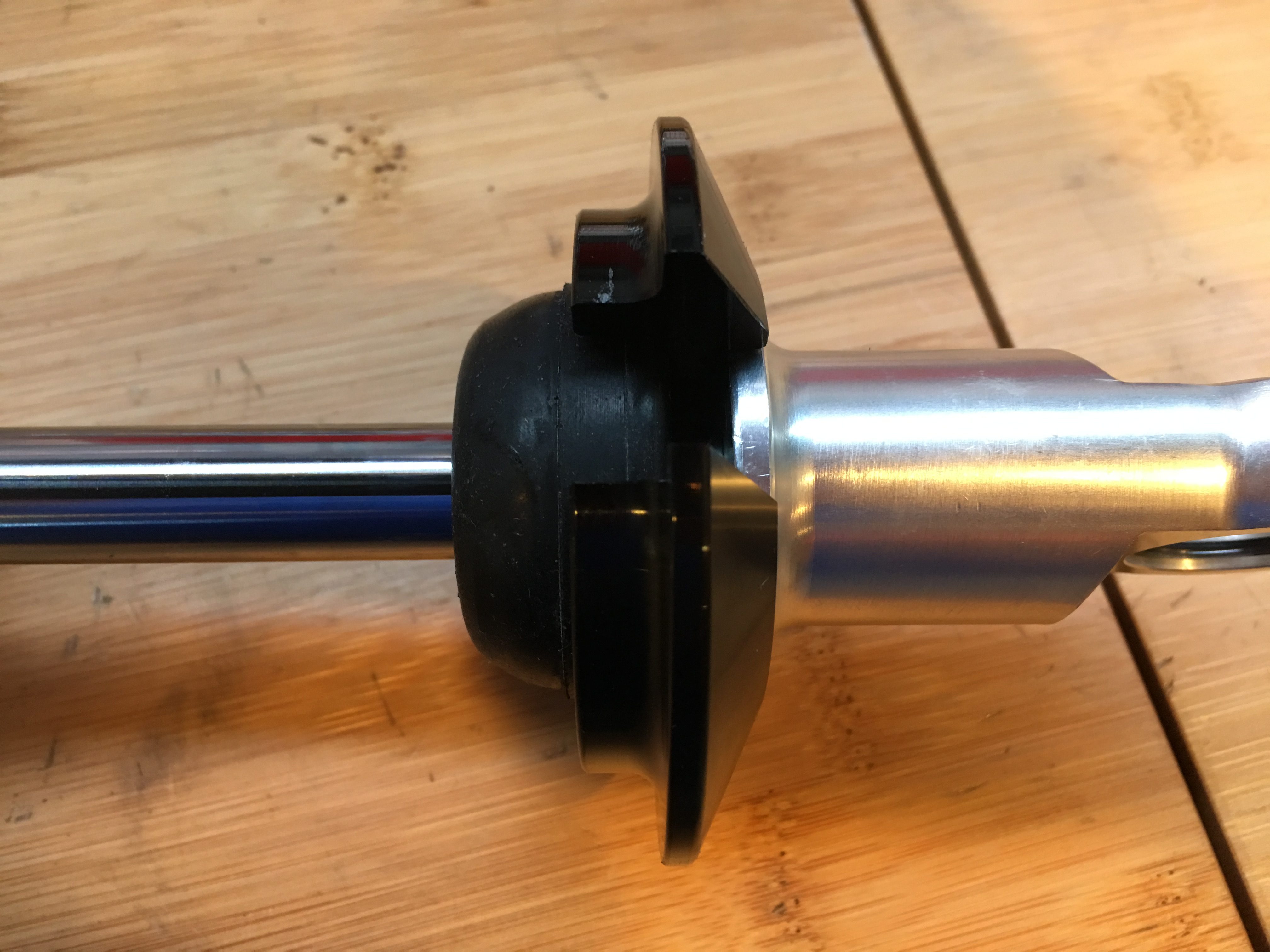
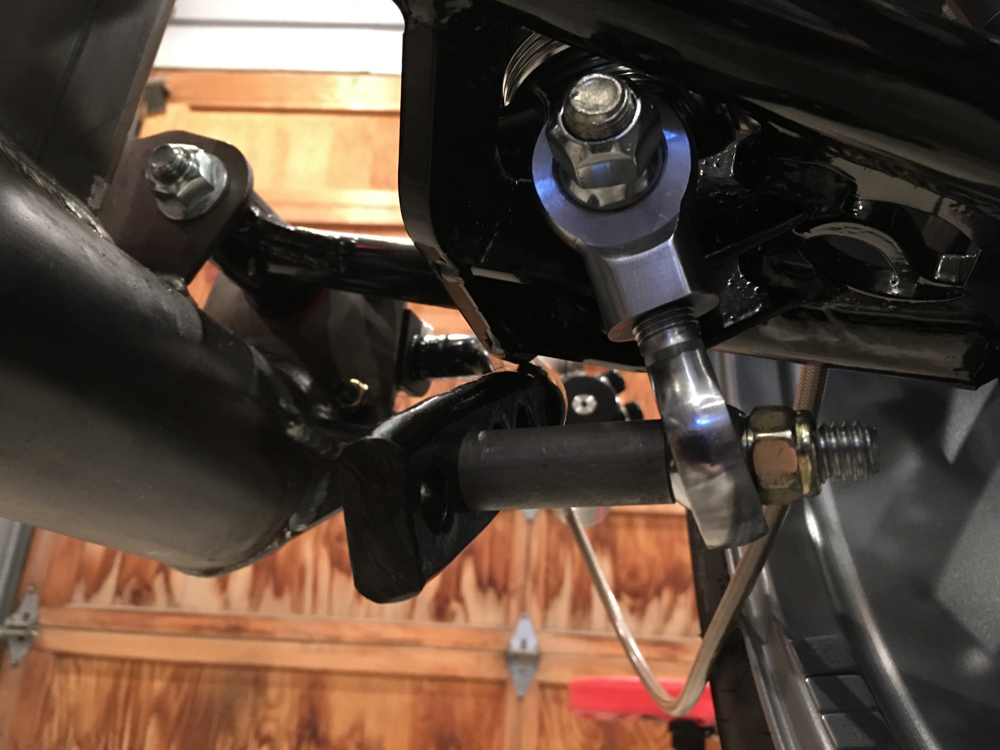
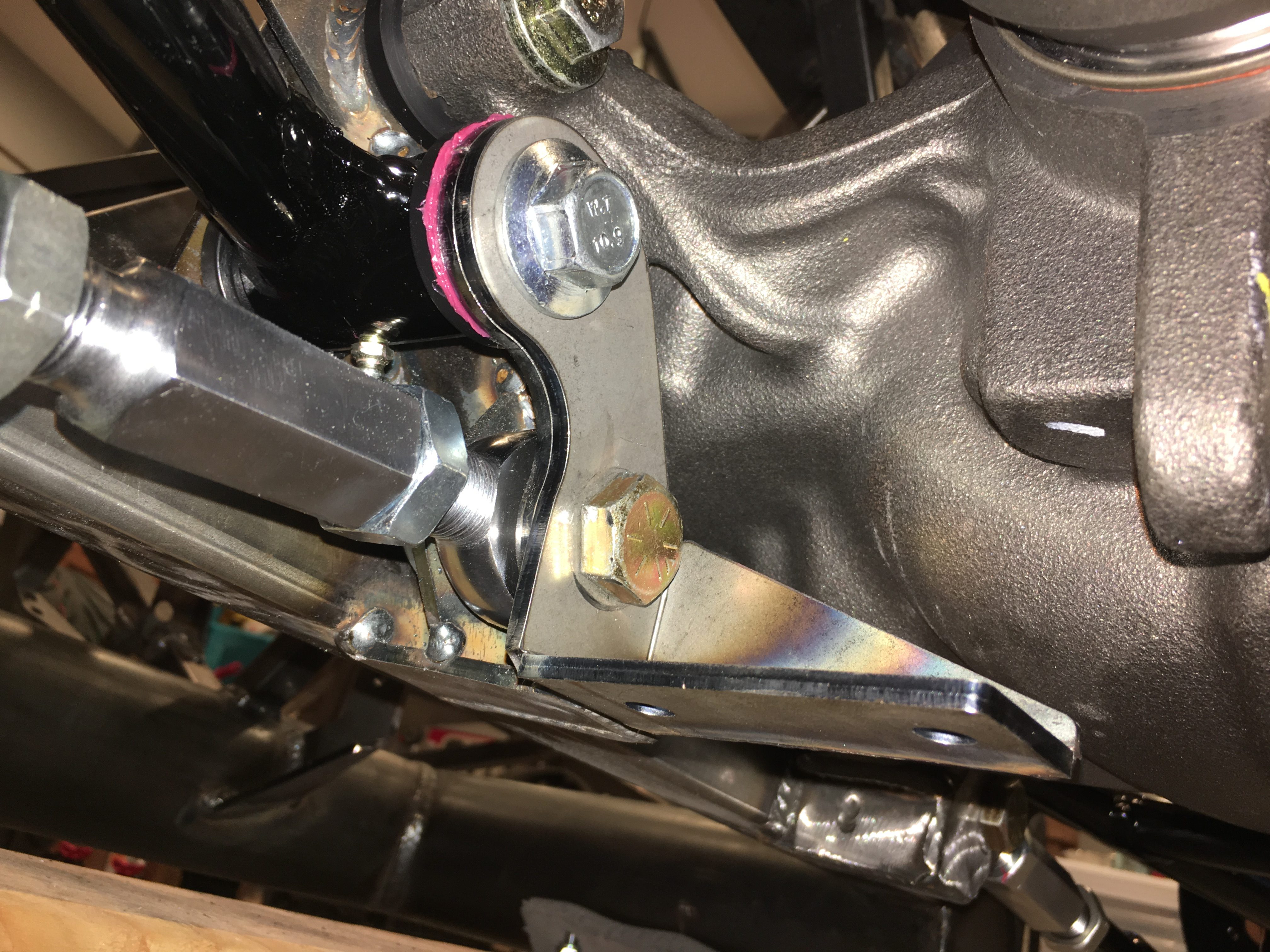
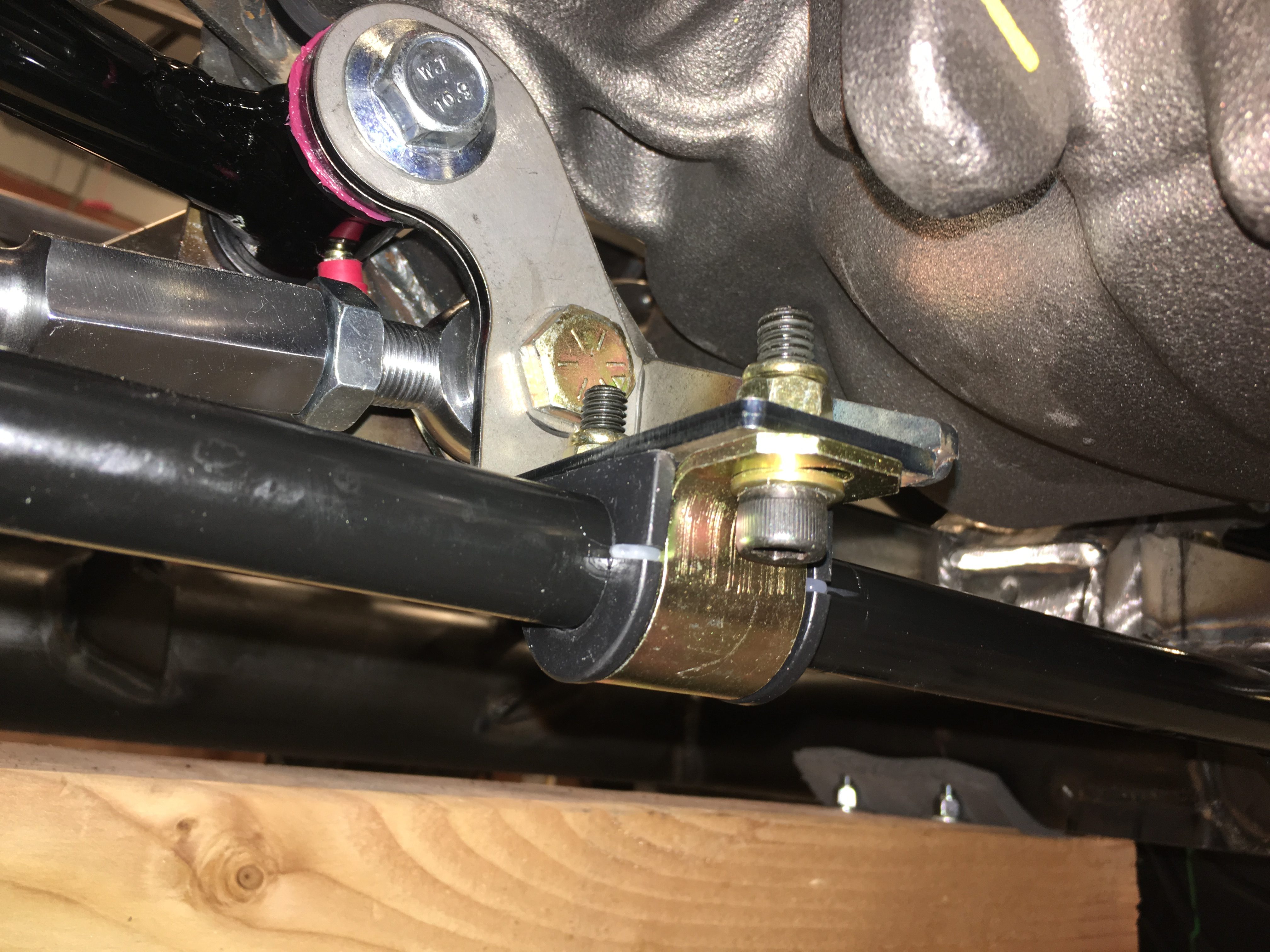
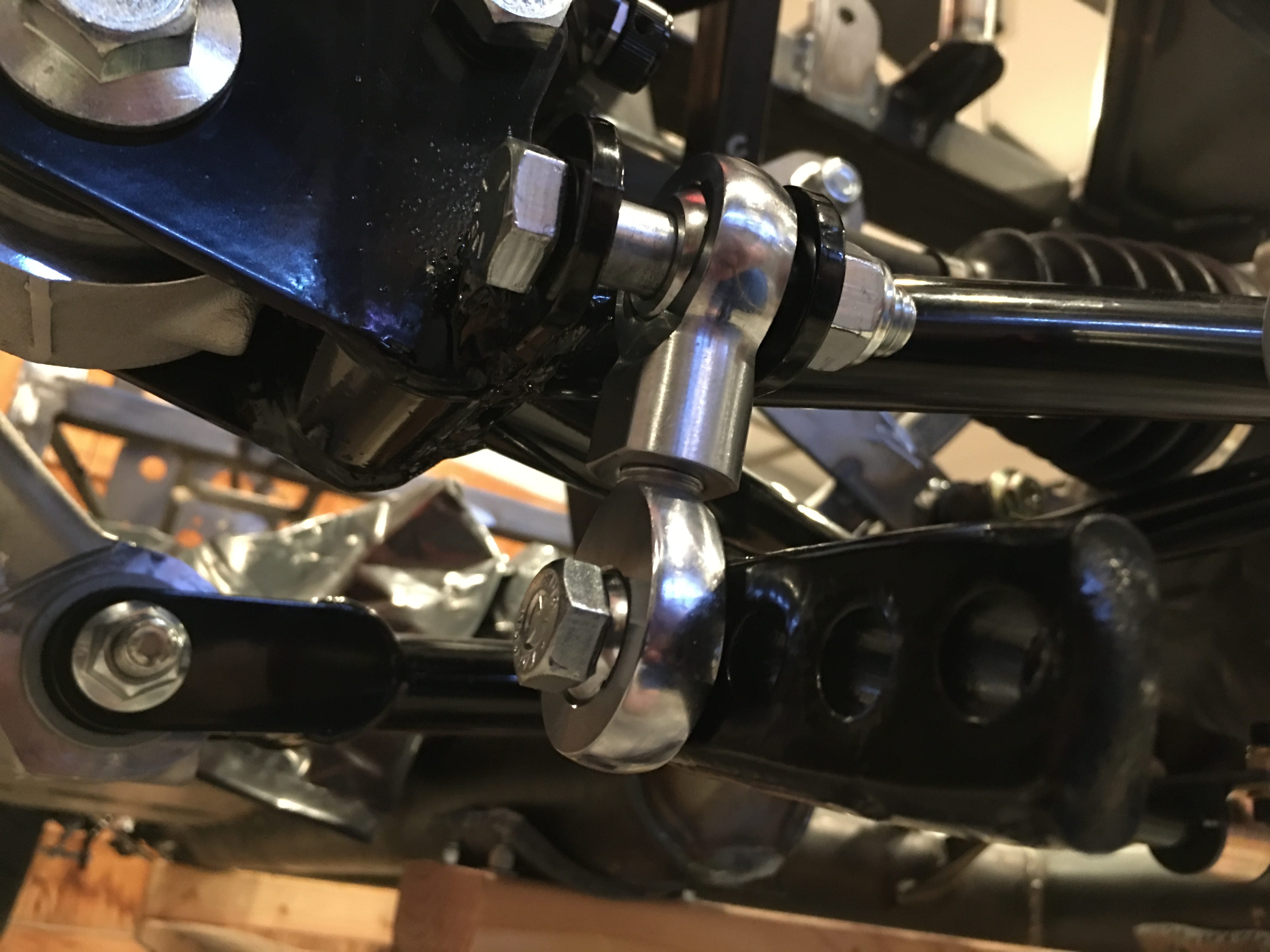
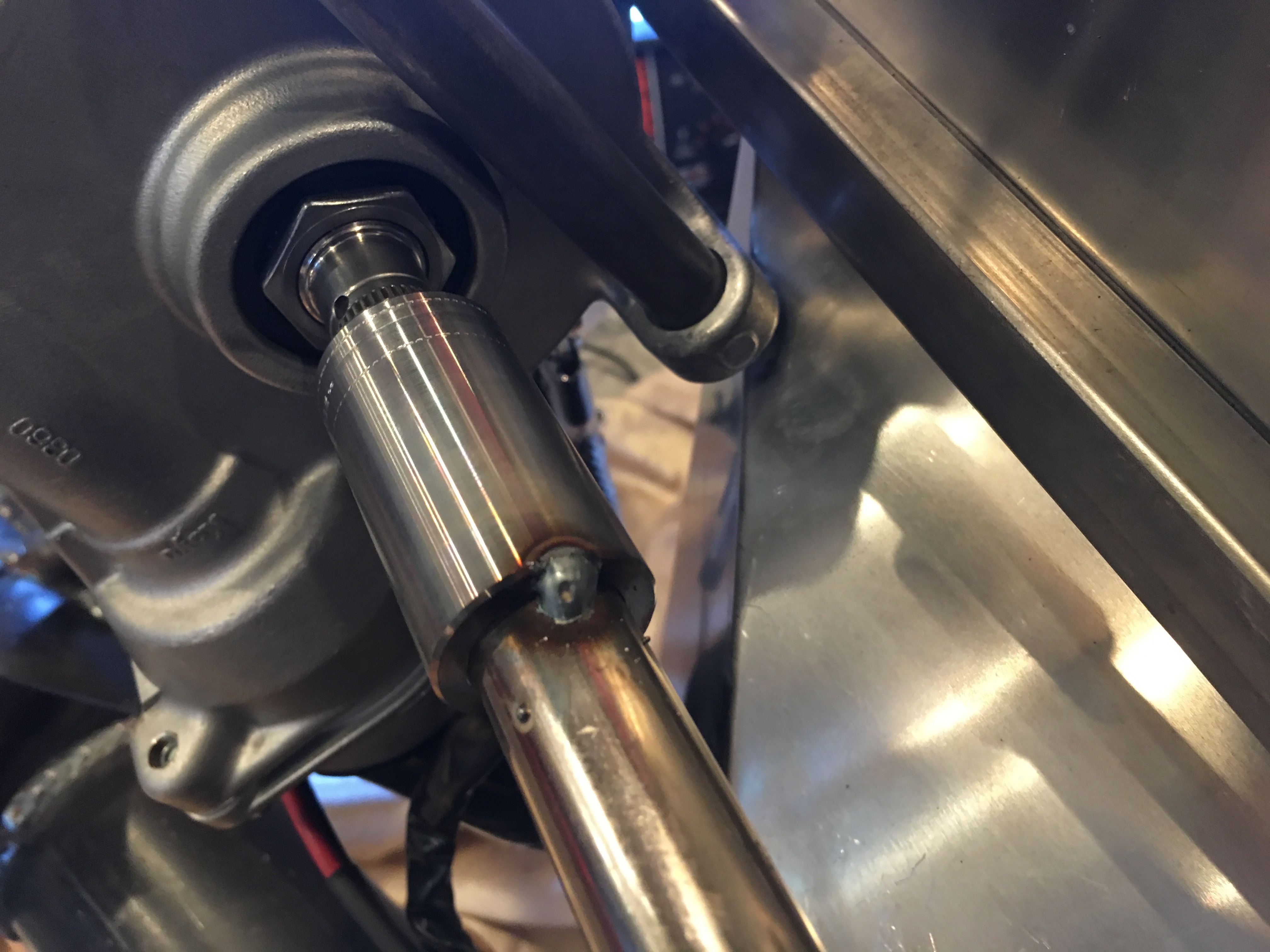
With the steering linking all bolted into its final location, I tacked the upper coupler to the steering shaft.

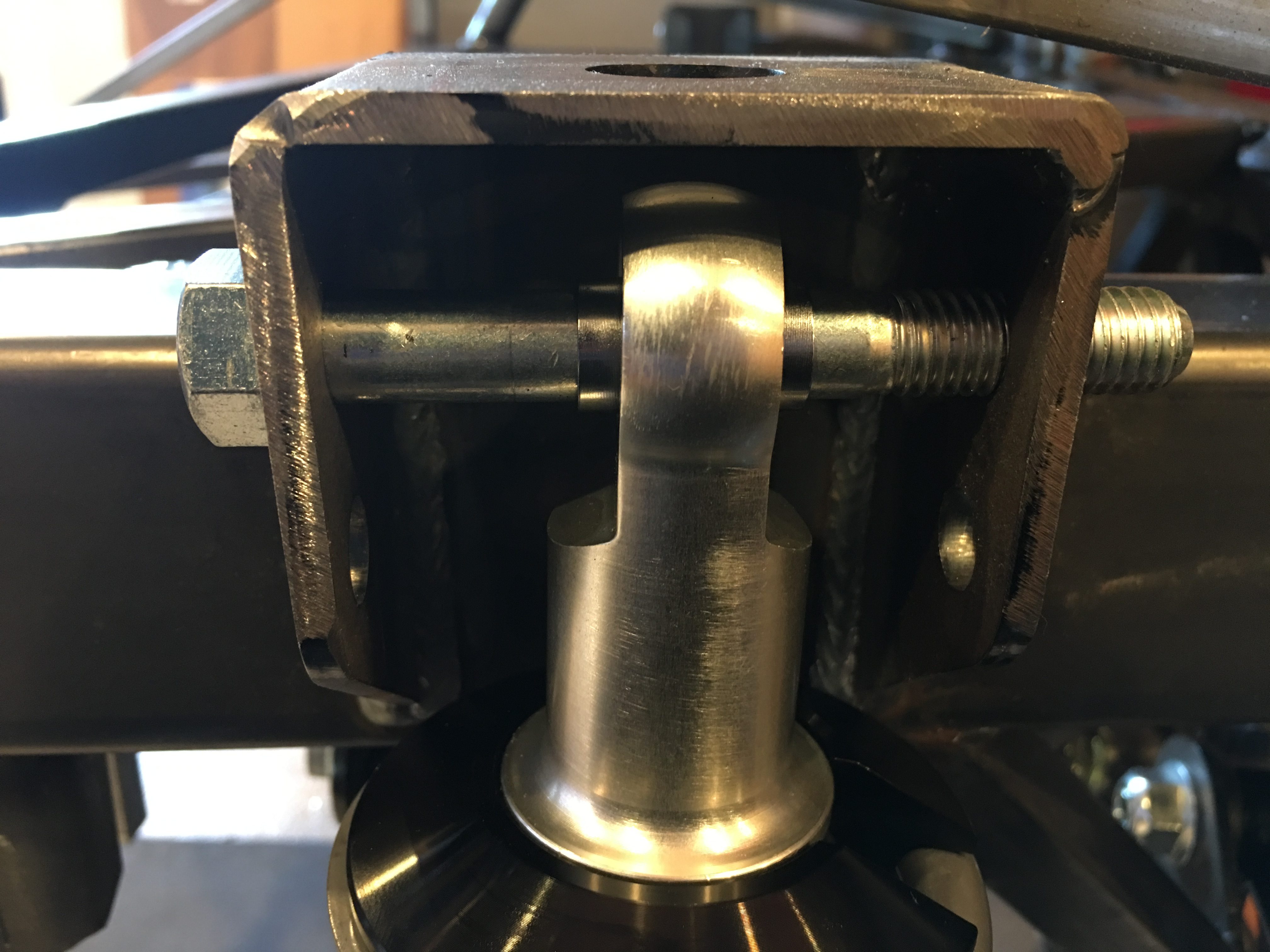
I also tacked the lower coupler.

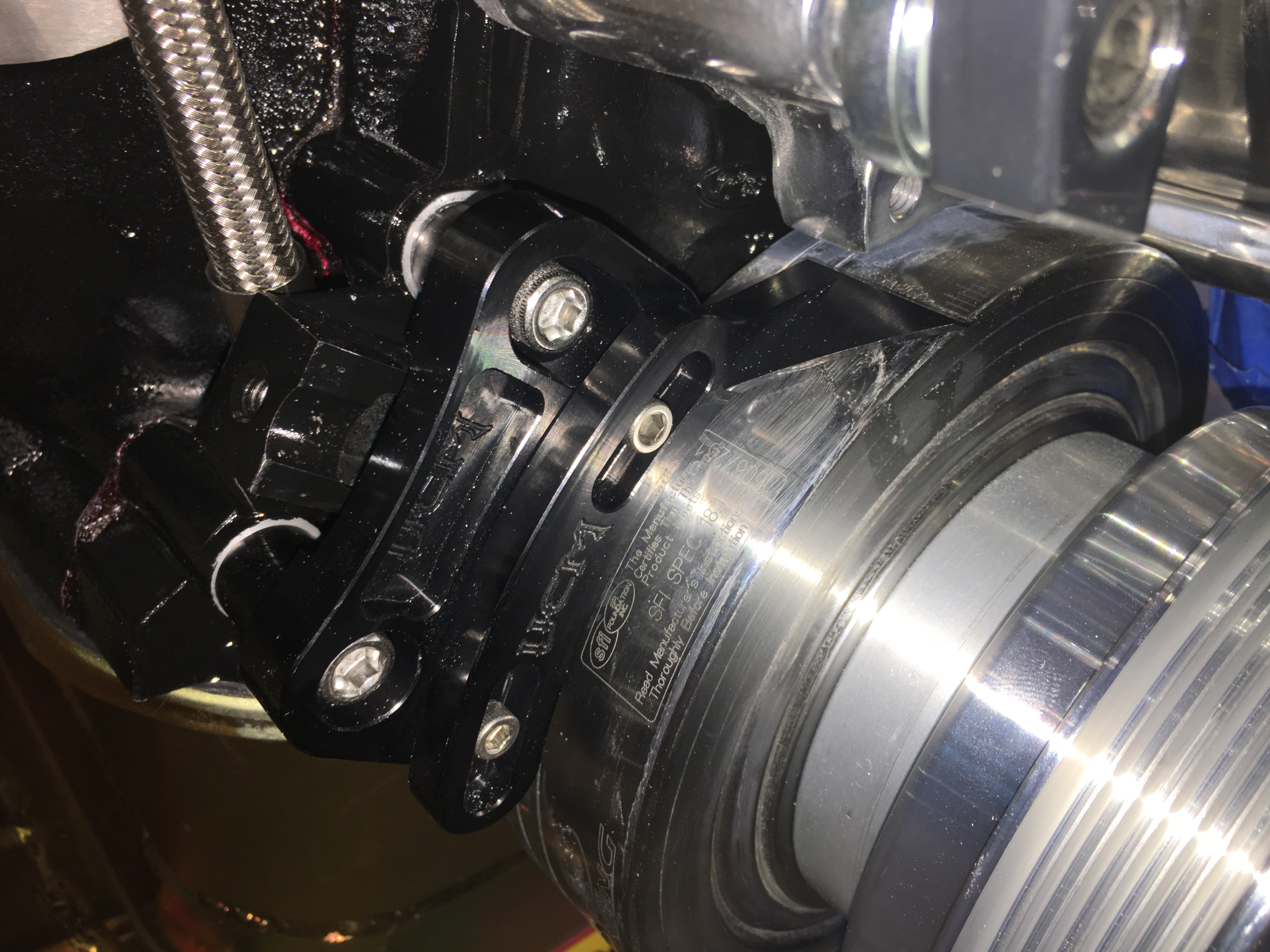
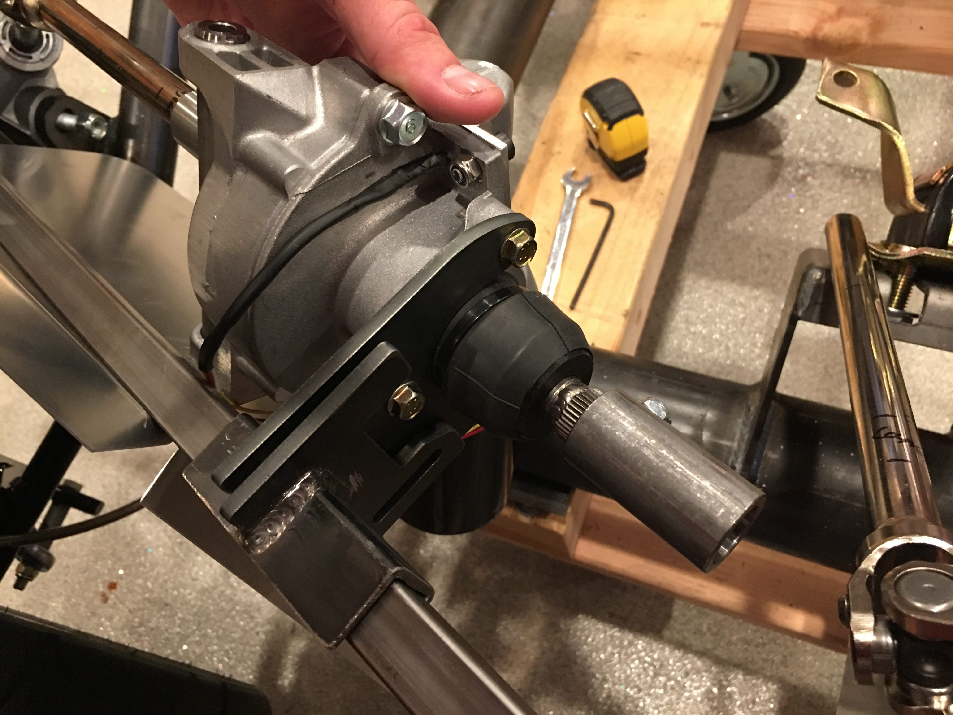
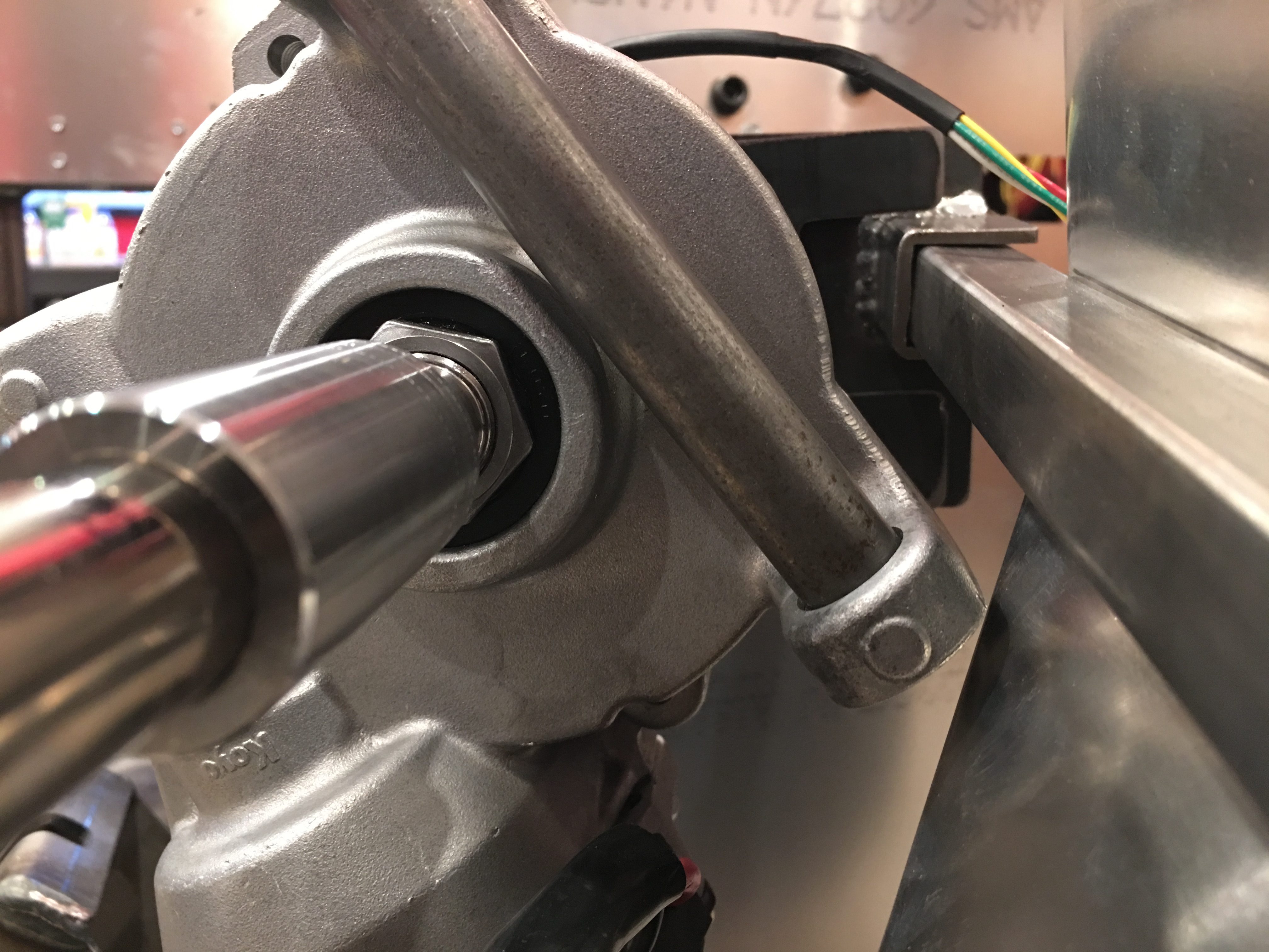
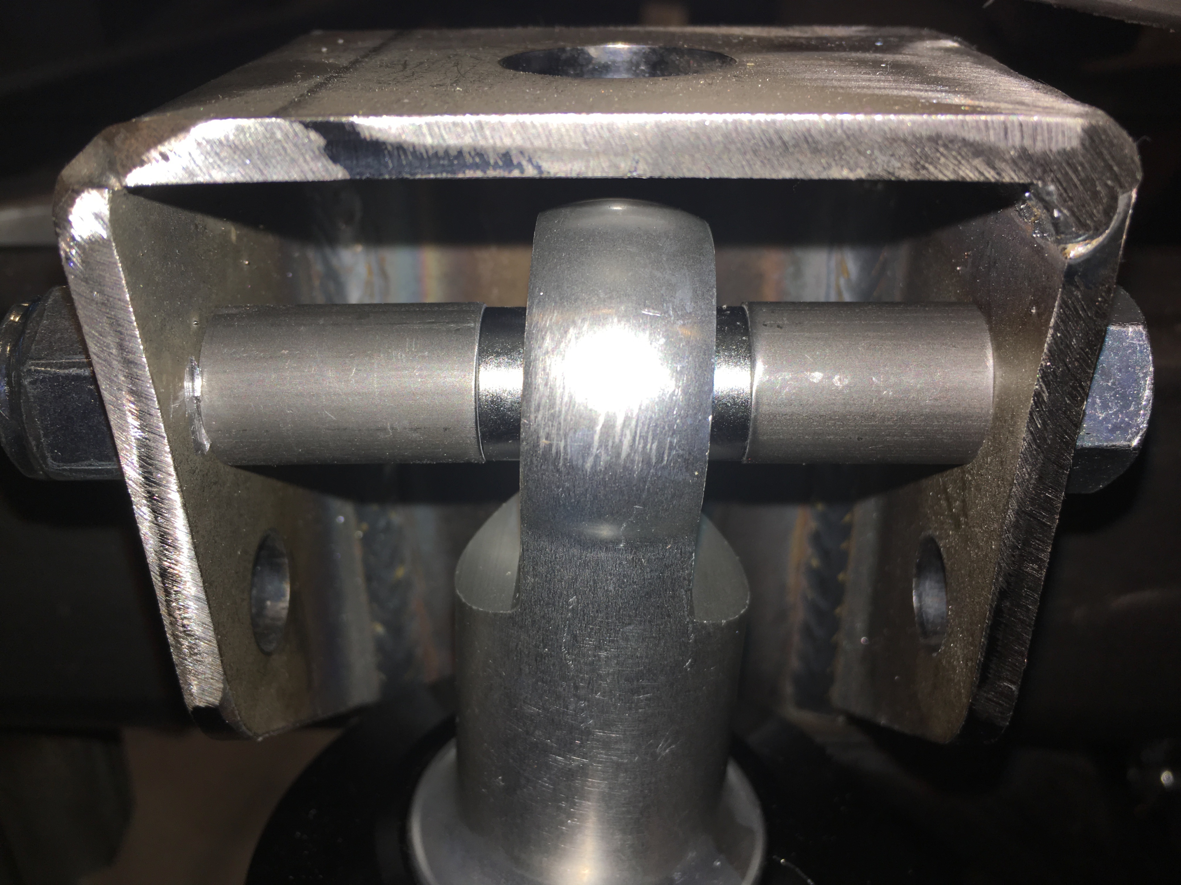
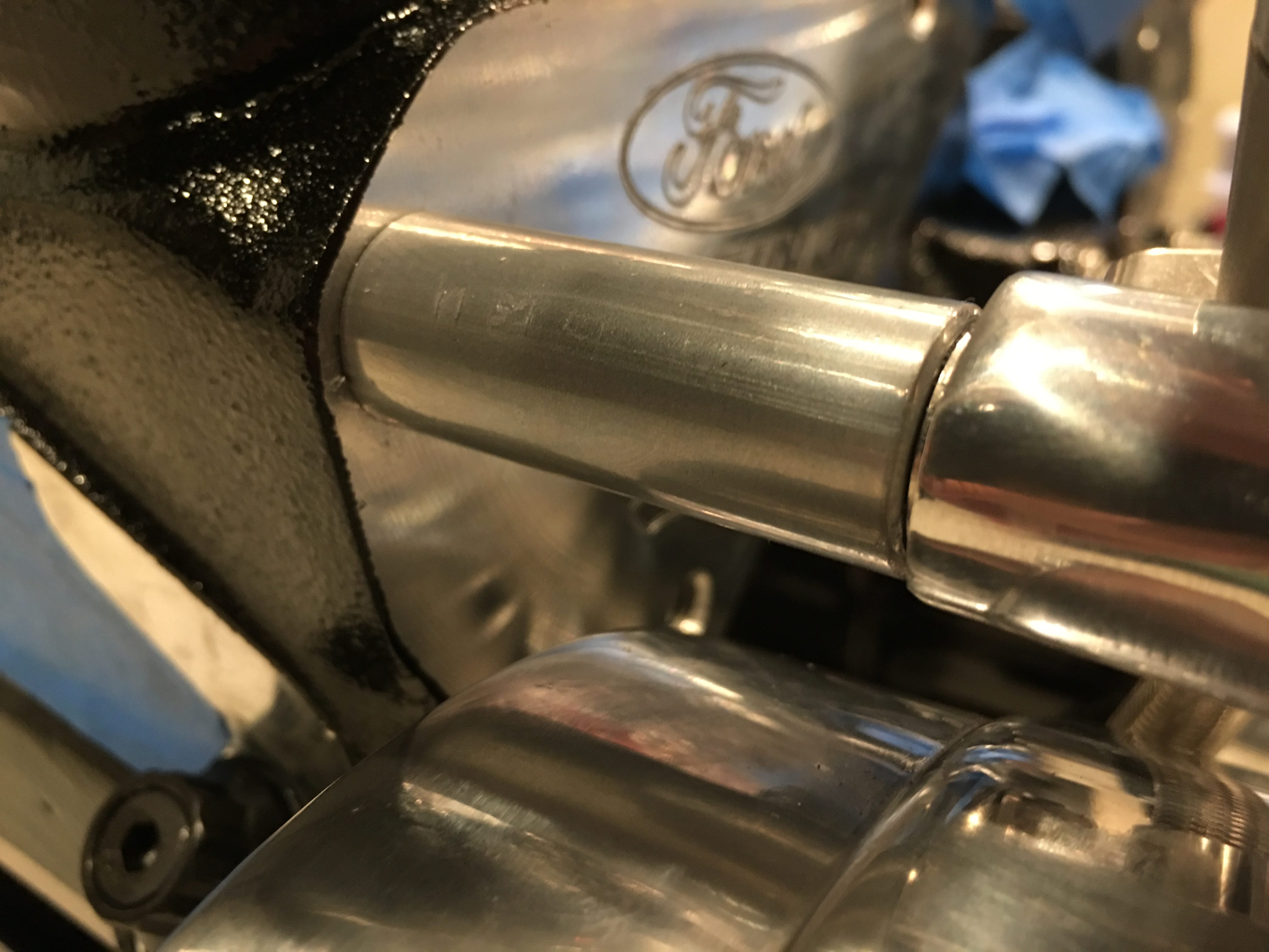
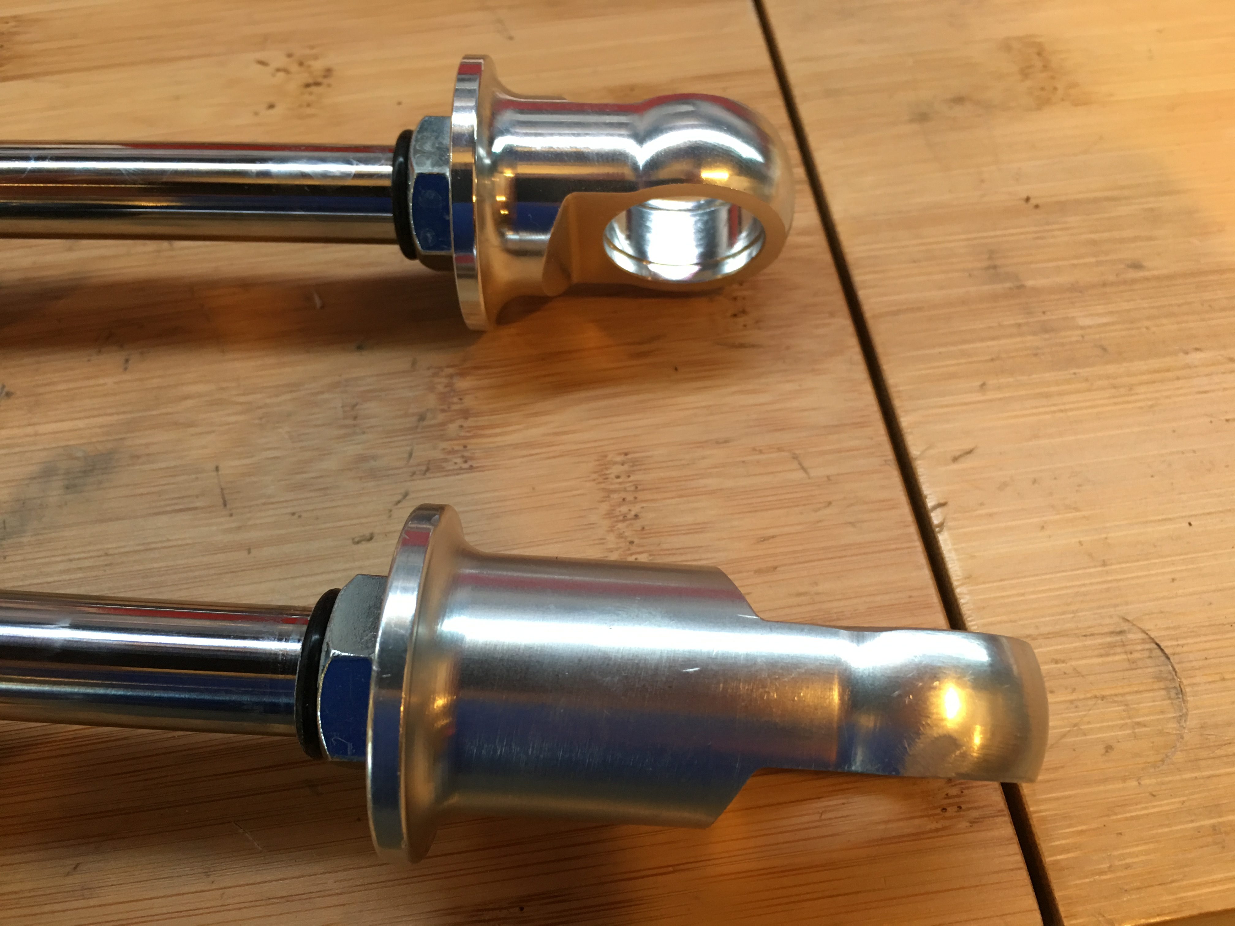
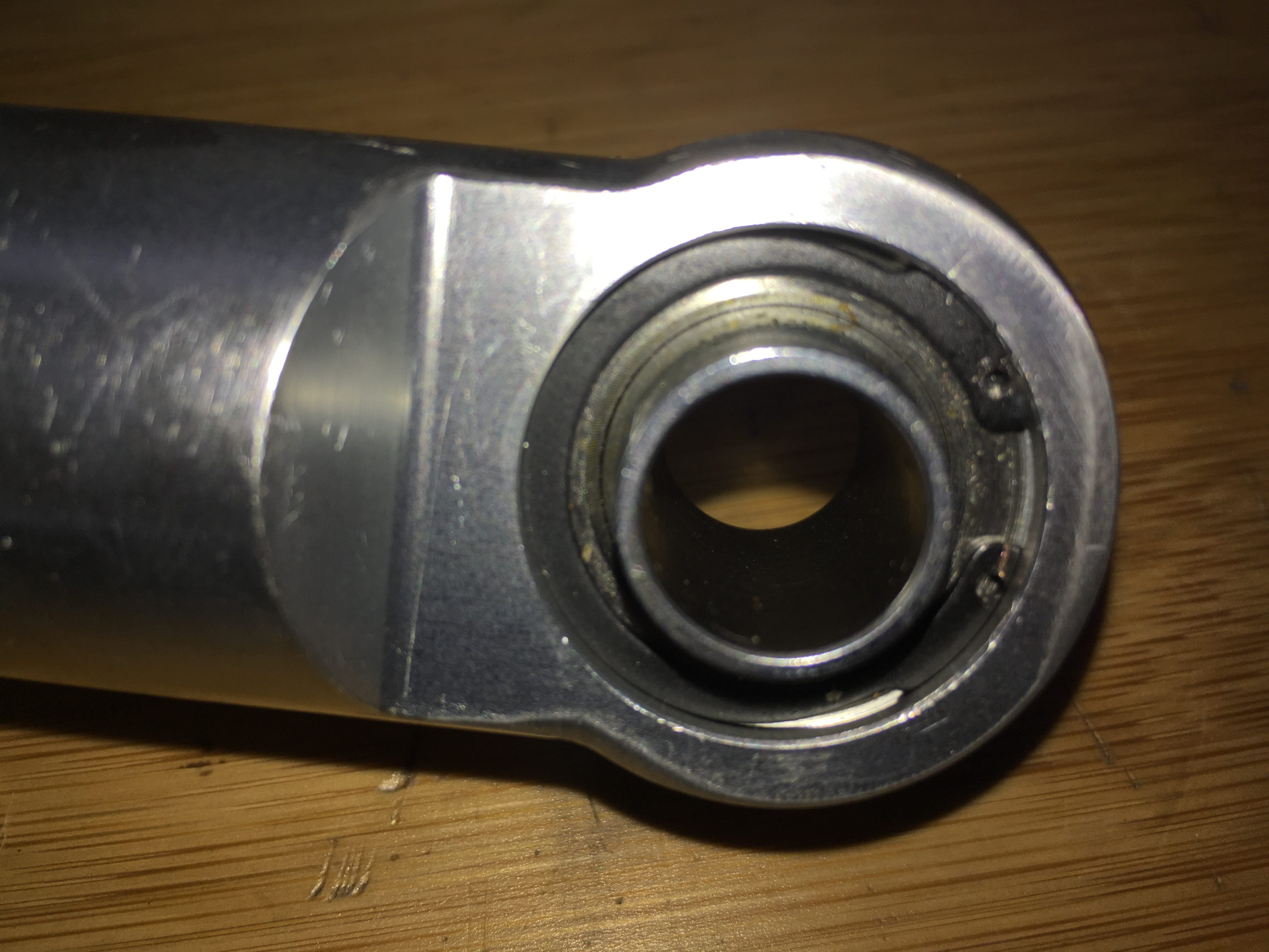
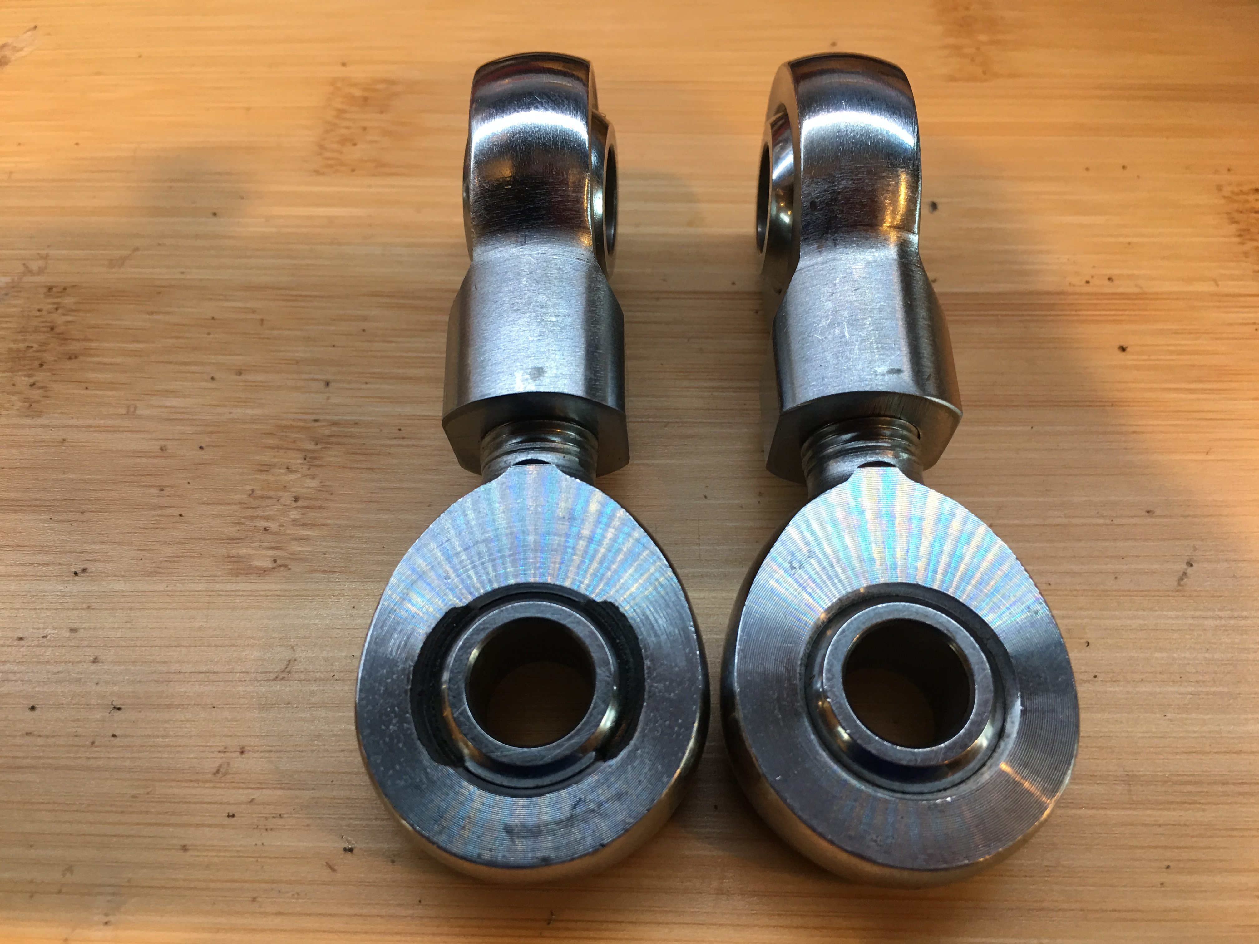
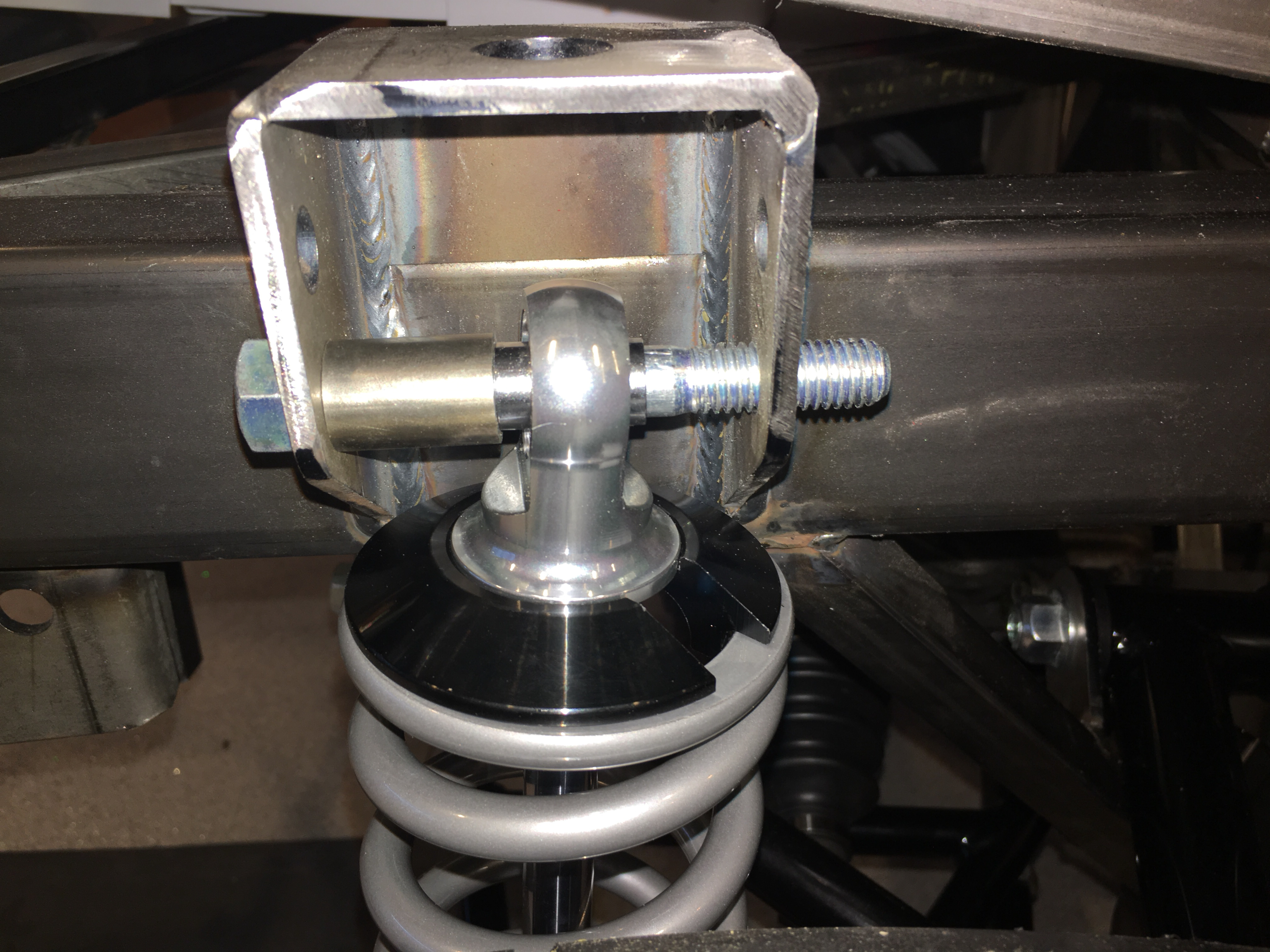
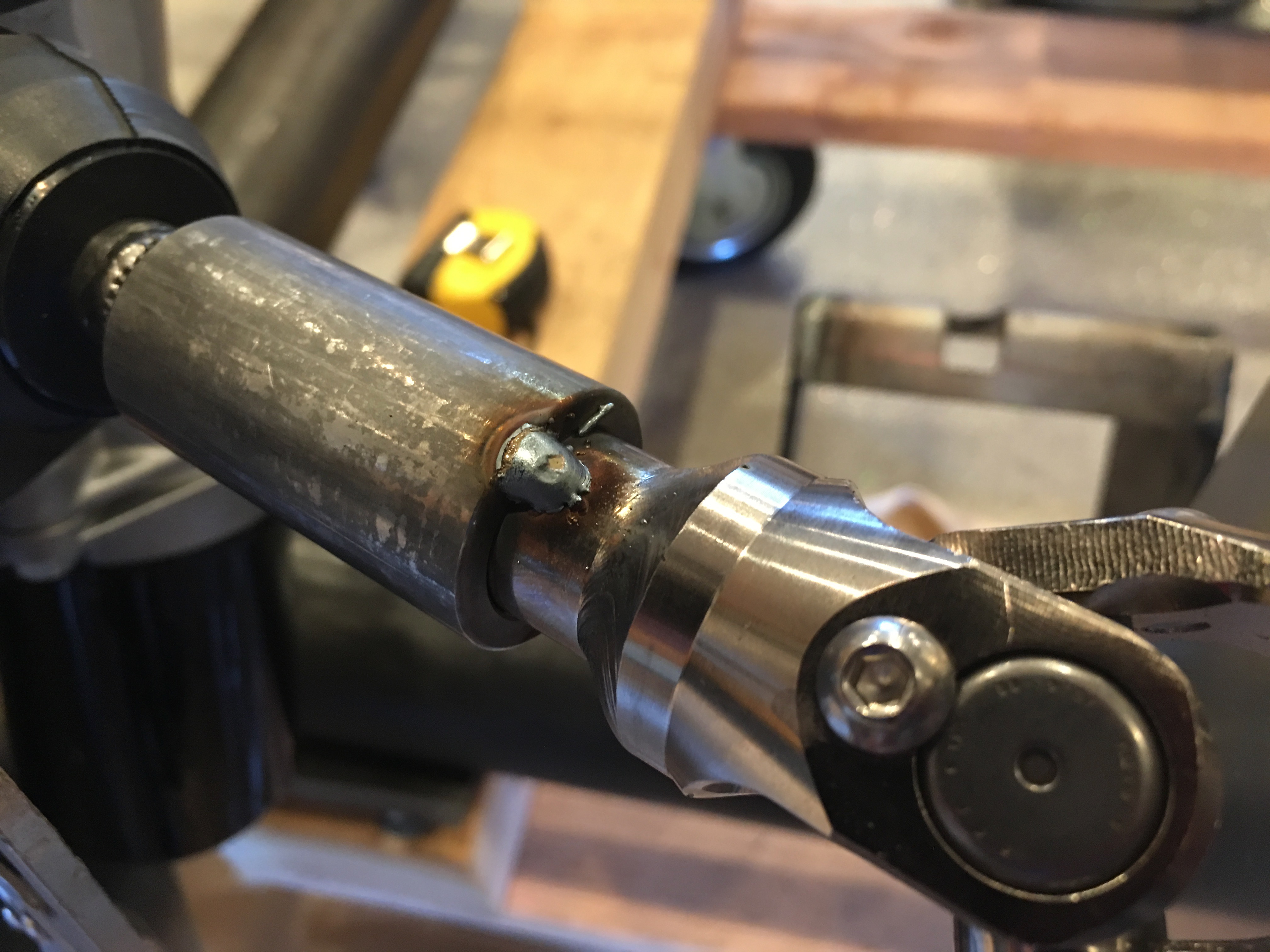
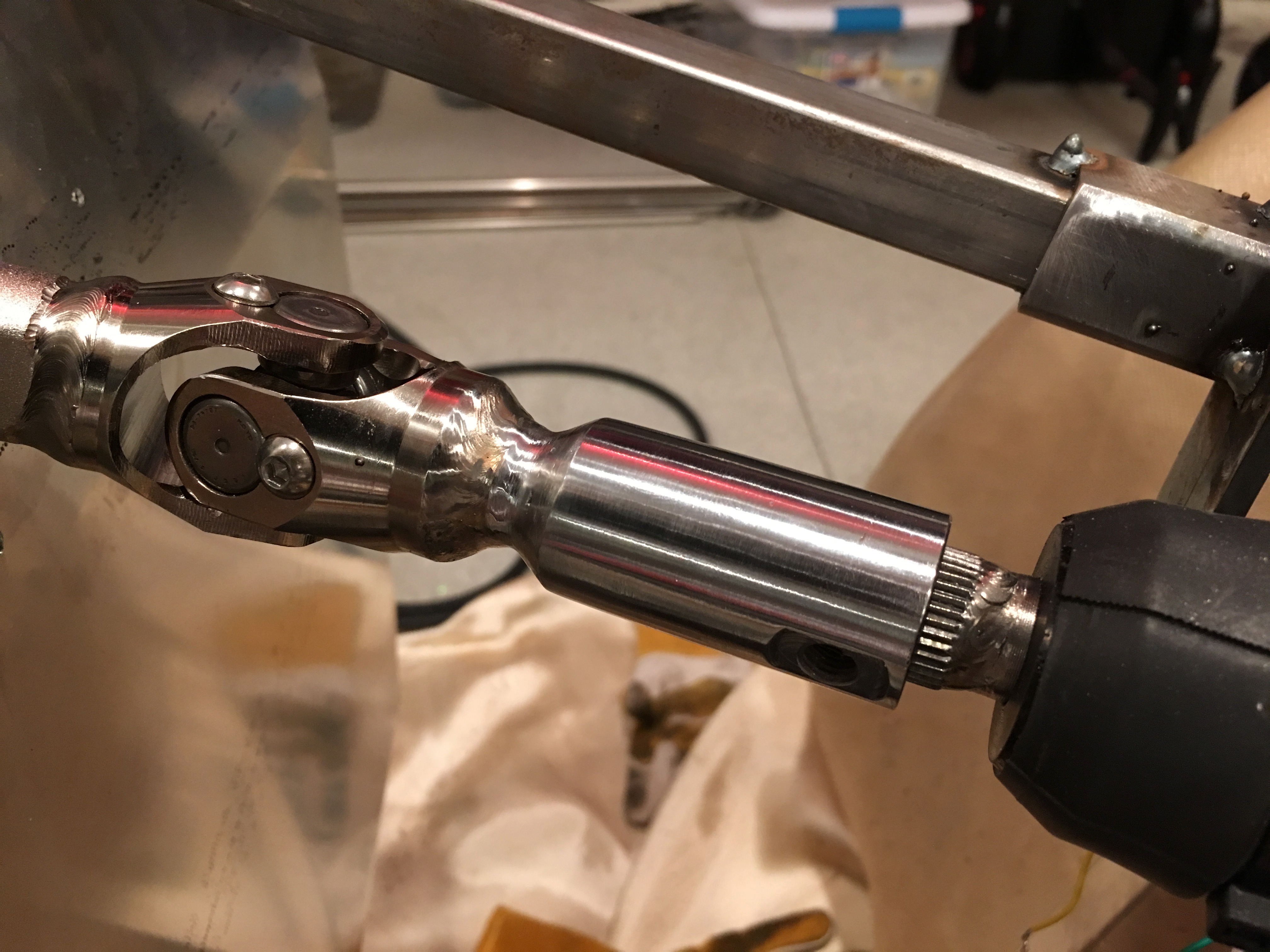
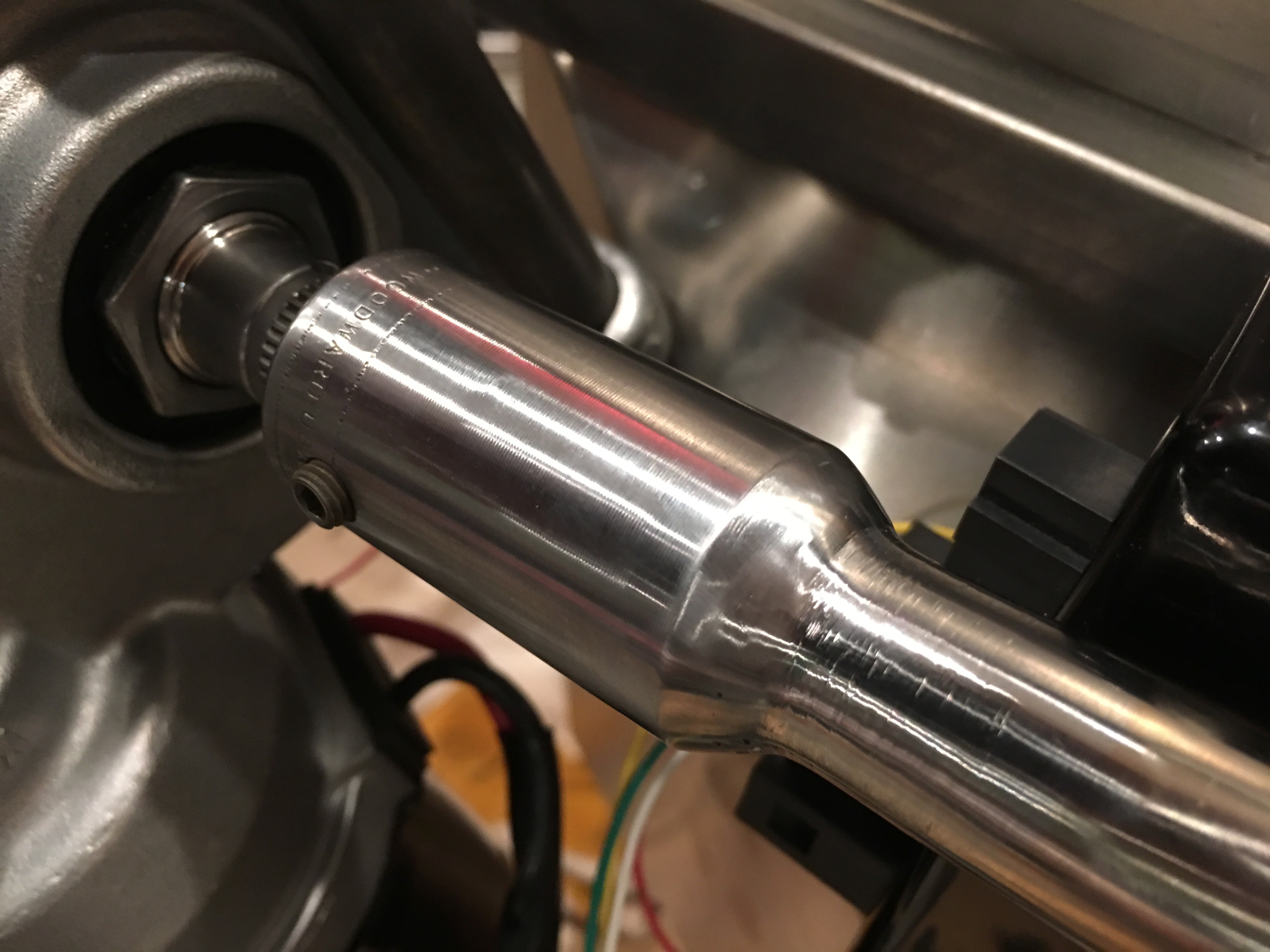
I then TIG welded the couplers all the way around and ground everything smooth. Here’s the upper coupler.

And here’s the lower coupler. I may have these chromed after the chassis comes apart for finishing.

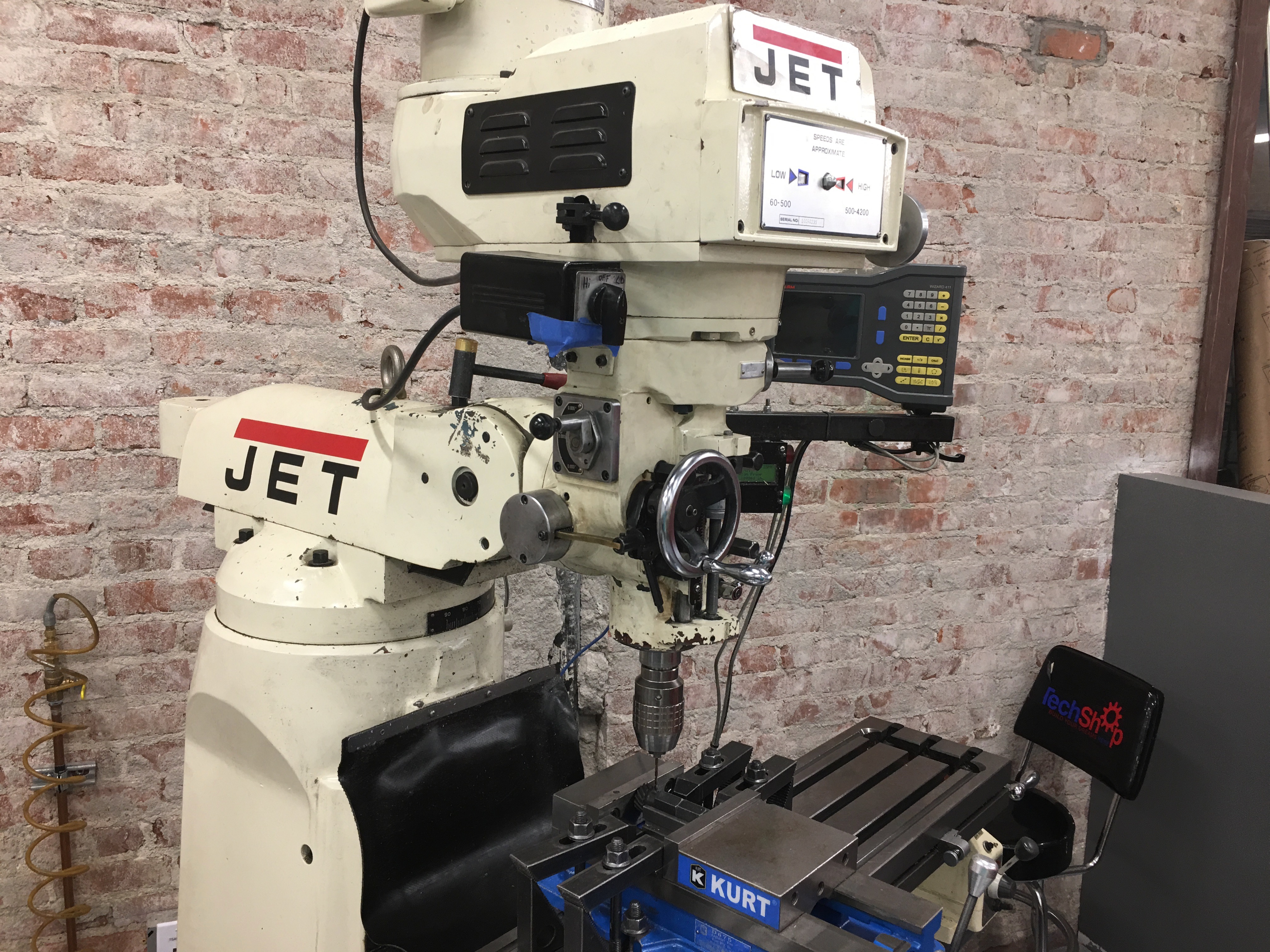
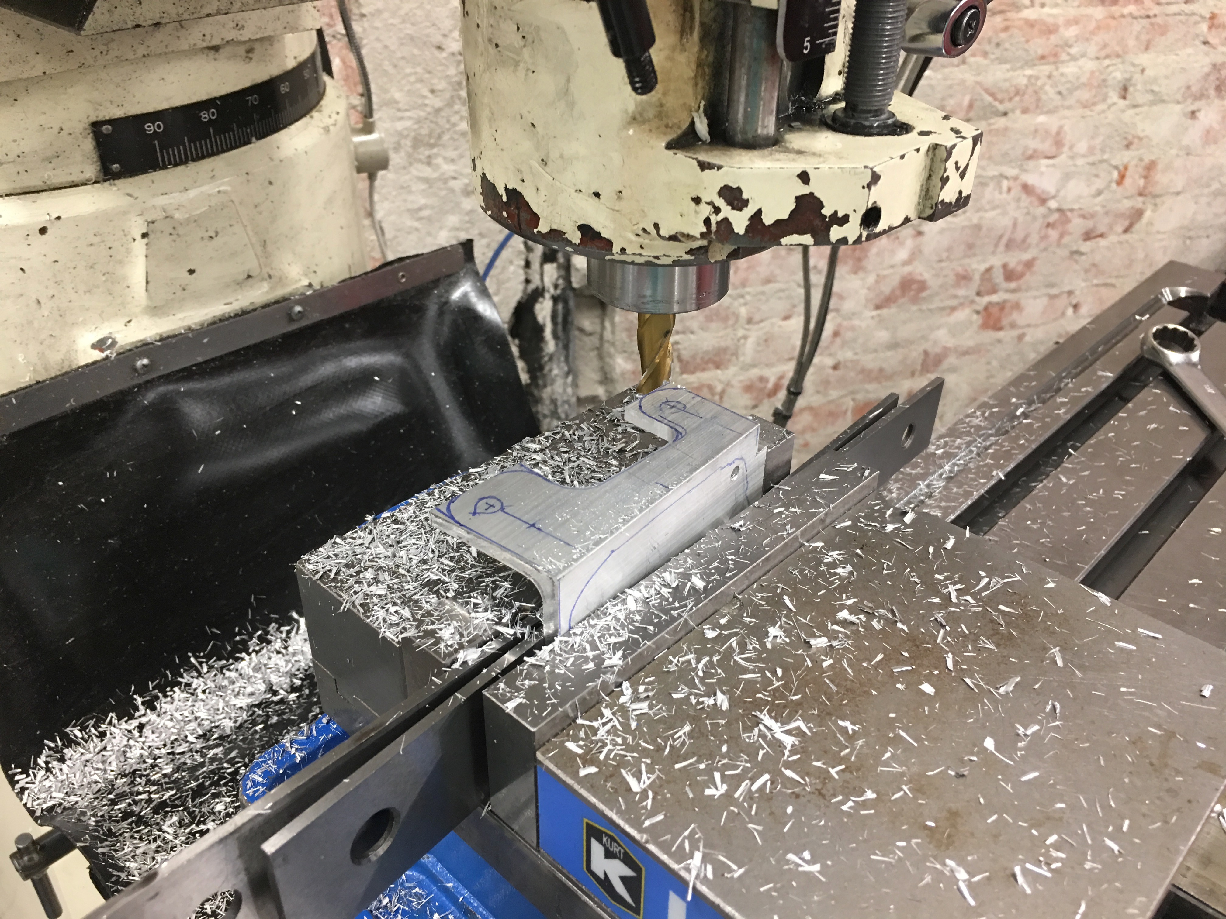
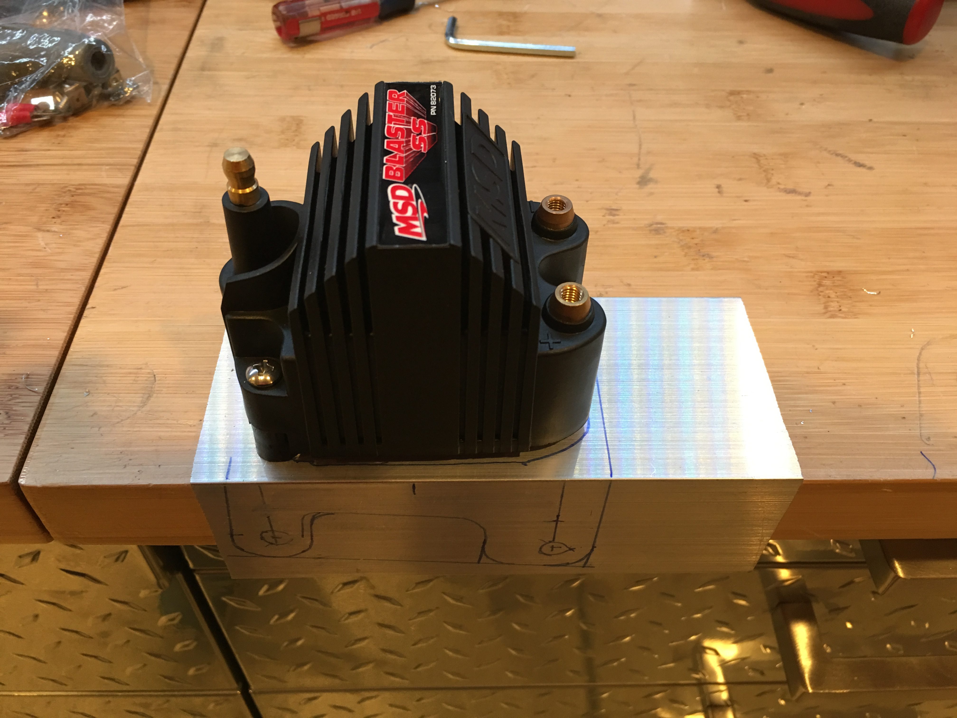
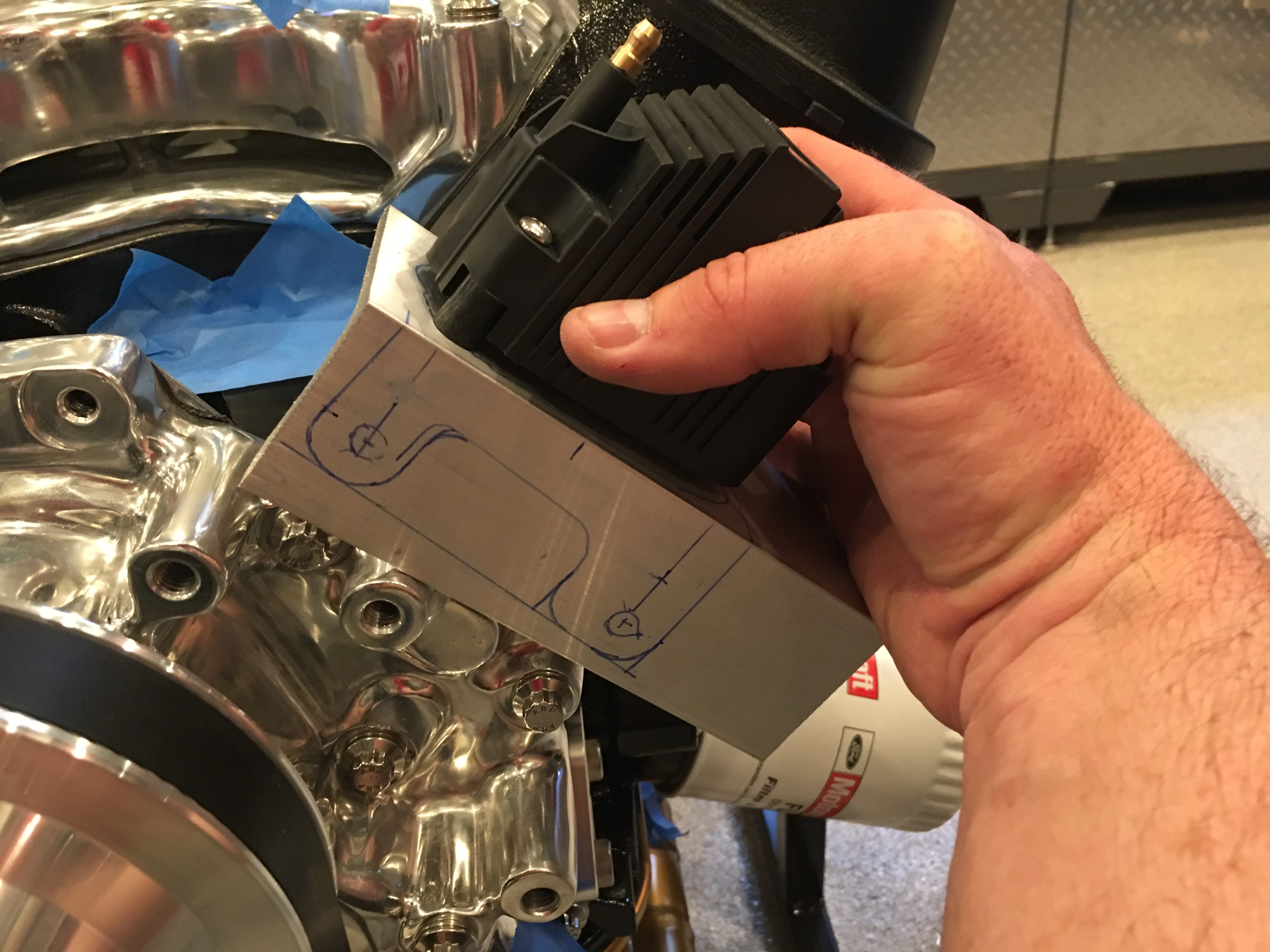
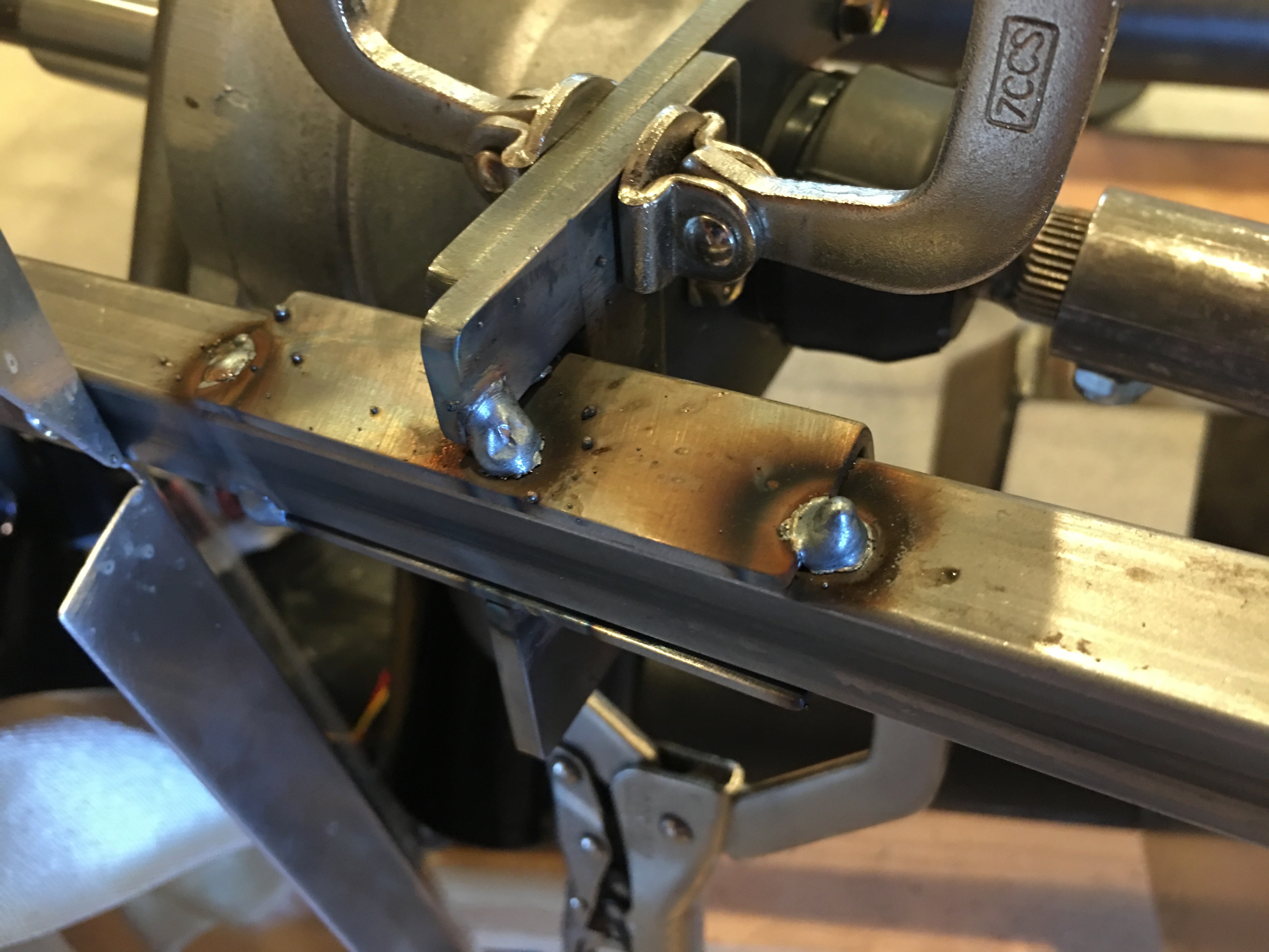
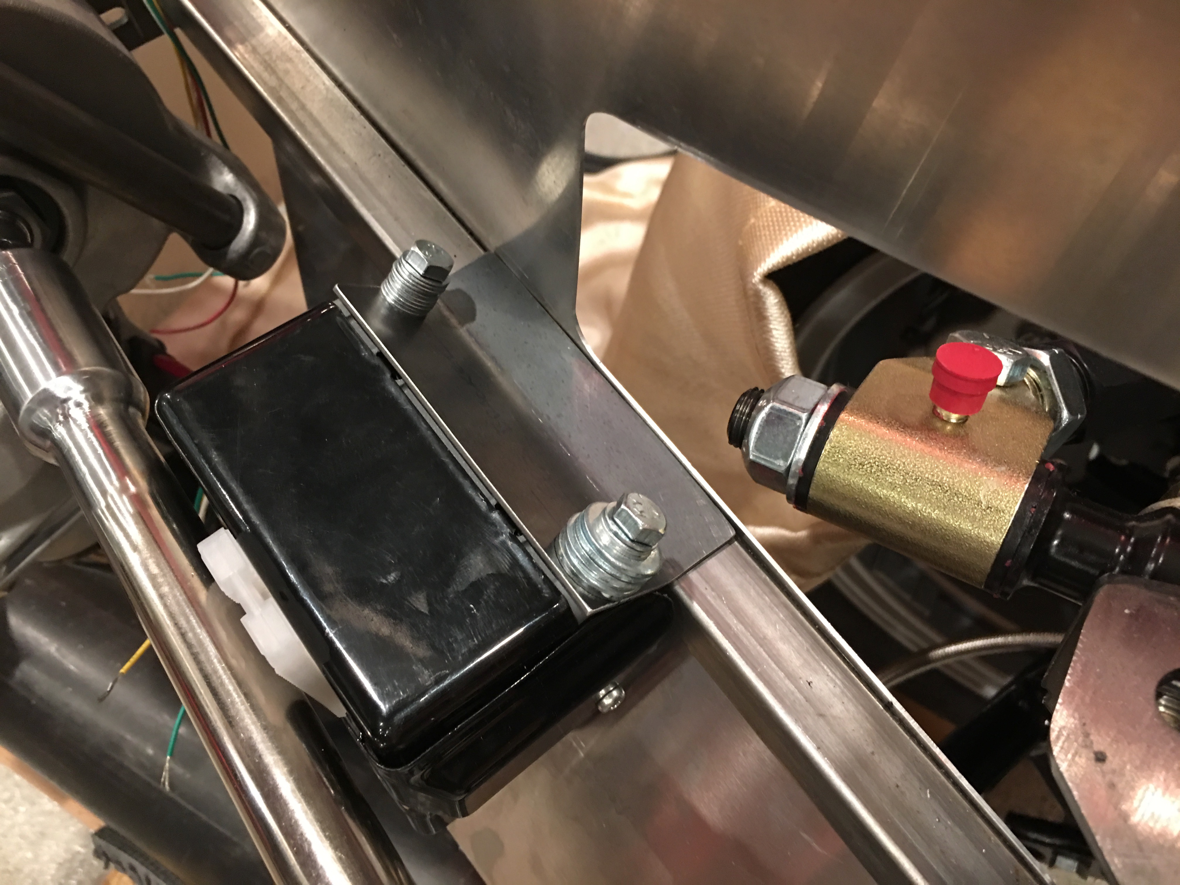
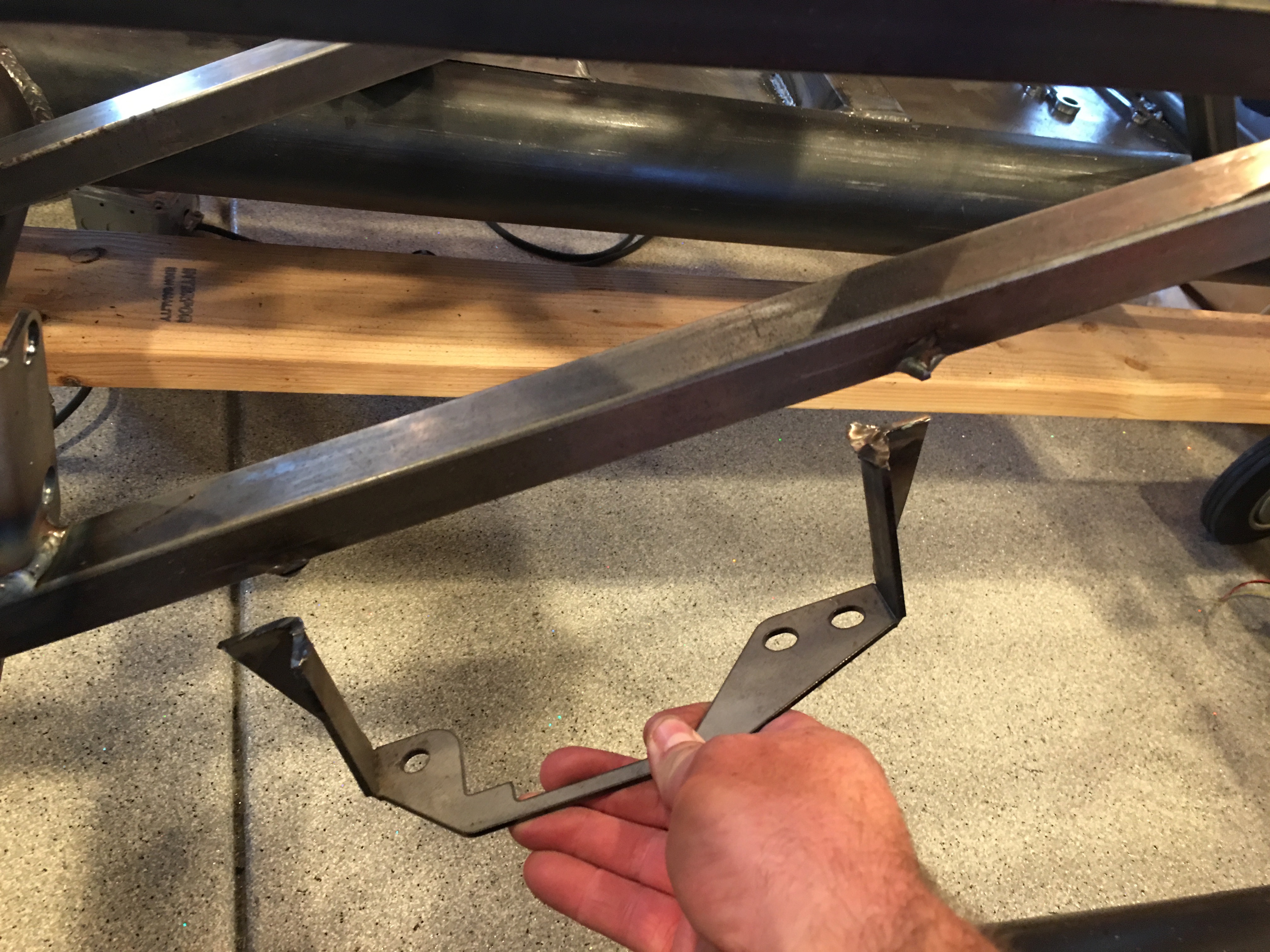
While I was at the TechShop, I fabbed up a piece of 16ga steel to attach the EPS controller to the chassis. The bolts are metric, so the only ones I had on hand were too long. I’ll pick up the right bolts before bolting this in for good.

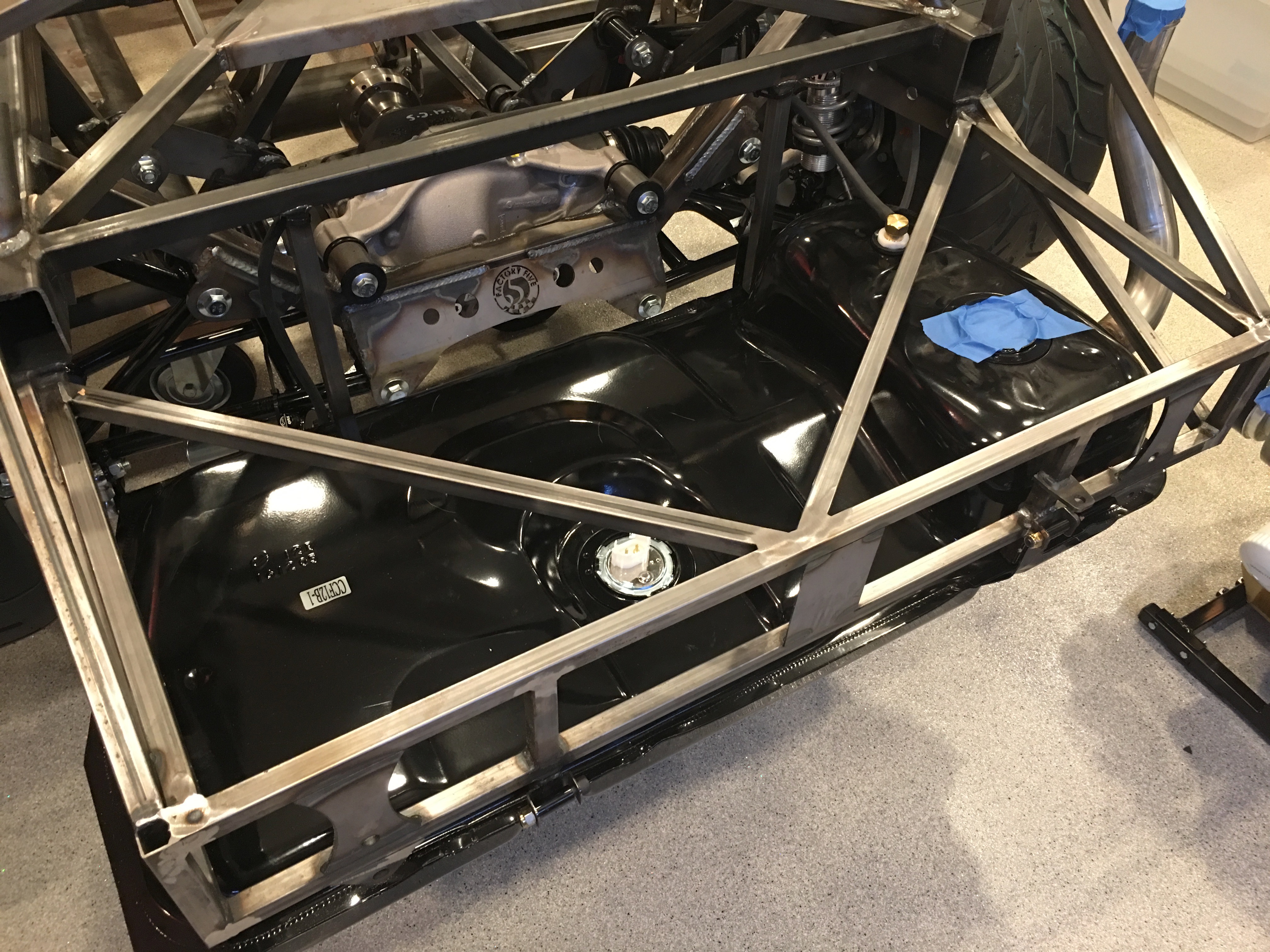
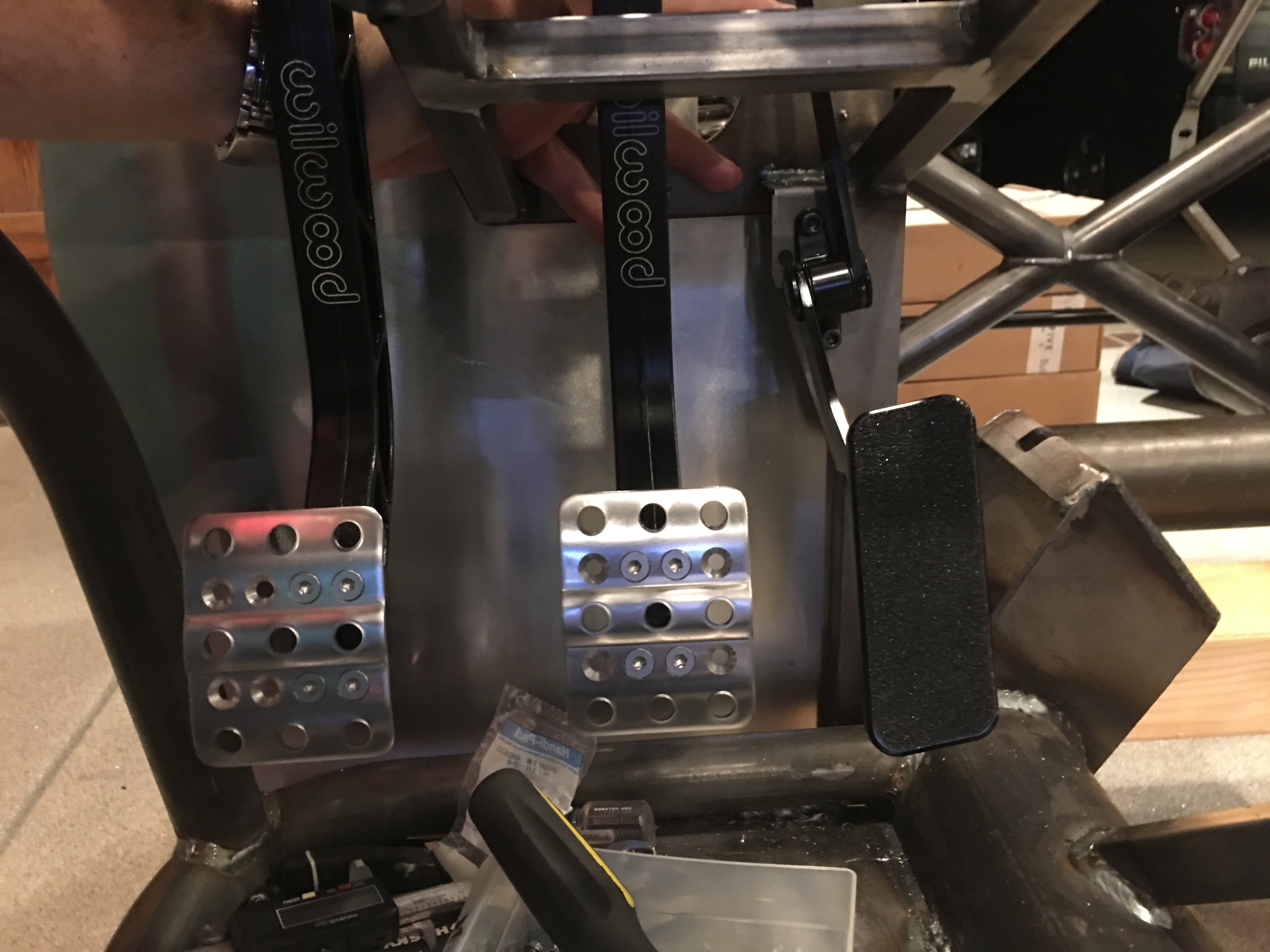
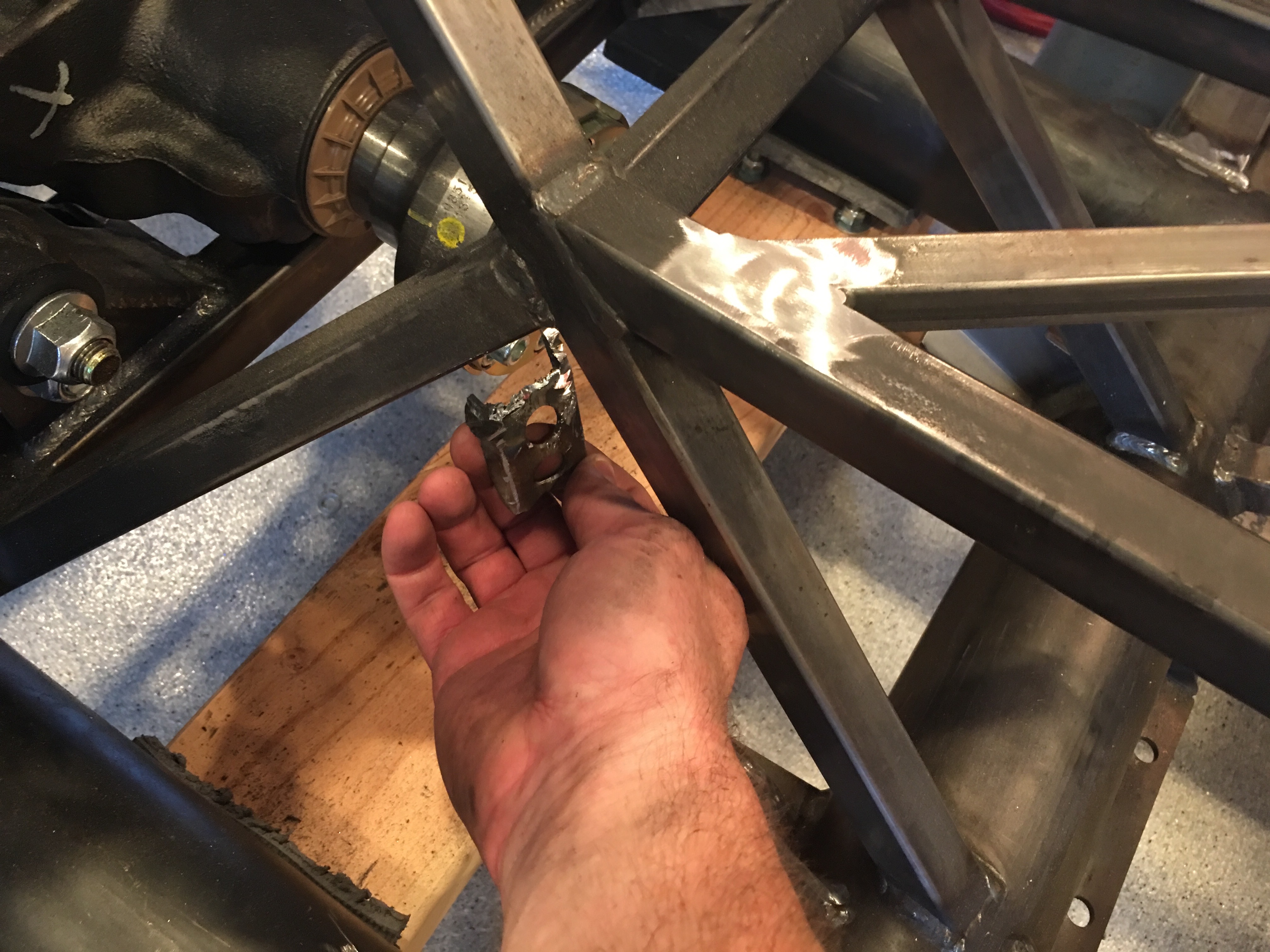
Since I’m relocating the parking brake, I cut off the bracket that holds the handle. I’ll have to fab up a bracket once I figure out the new location.

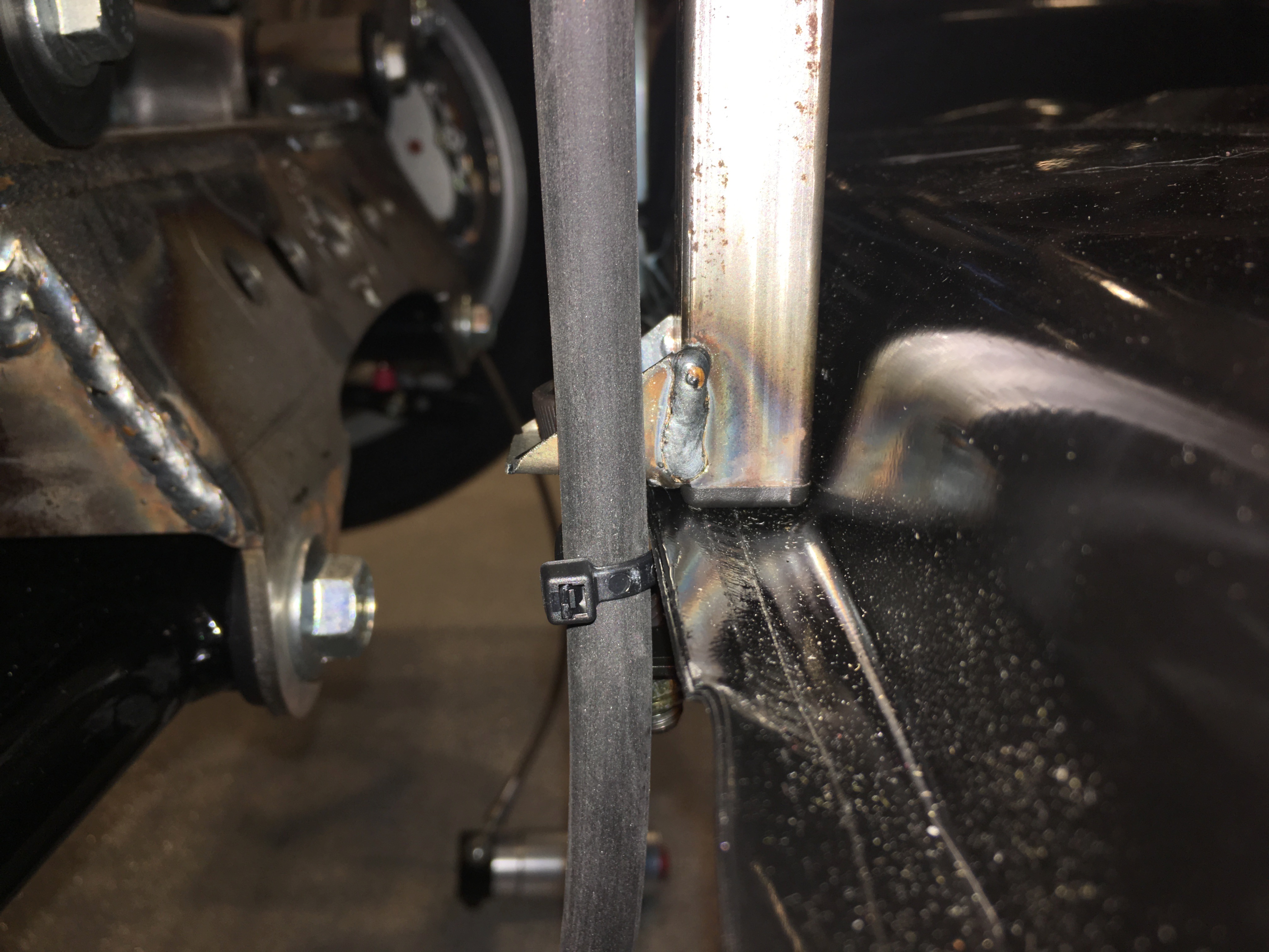
I also cut off the bracket that hold the parking brake cables. I really wish I had cut this off before installing the differential; it was a real challenge cutting this off while working around it.

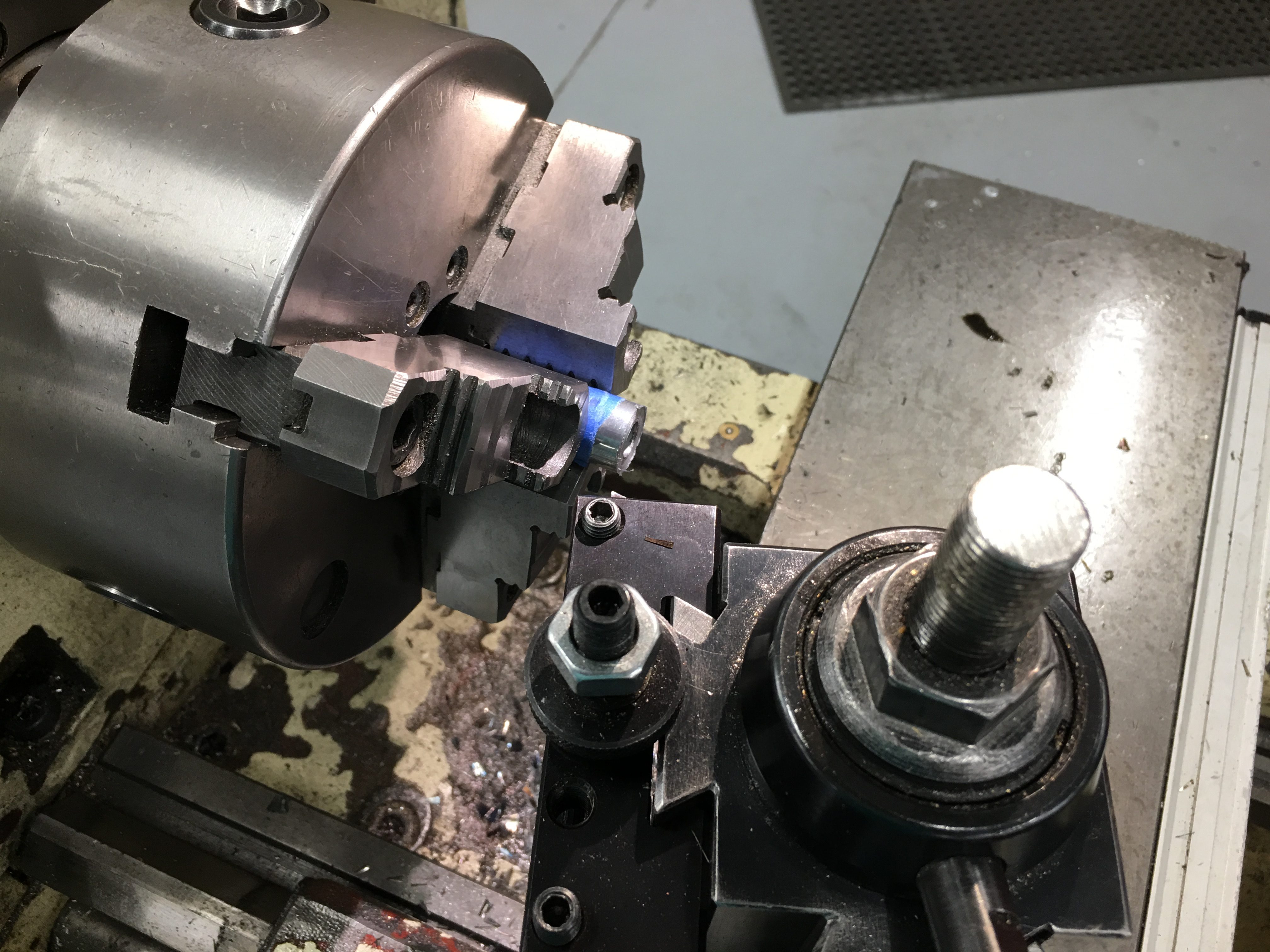
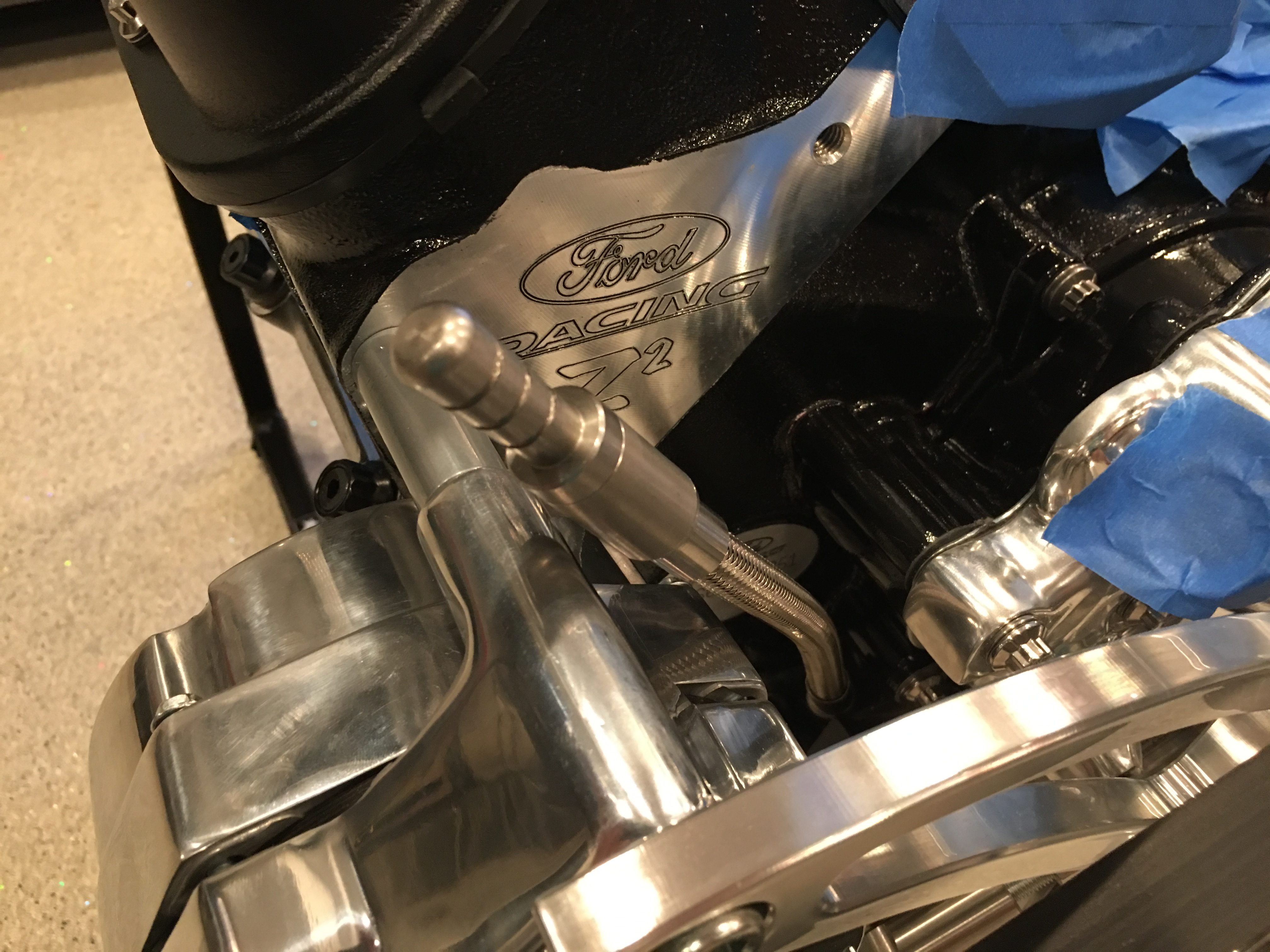
I originally purchased a timing pointer that mounts at the 2 o’clock position, but it turns out that that would be pretty hard to see since we’re using a water pump with a driver side inlet. I replaced that with one that mounts at the 11 o’clock position, but it interferes with a bracket on the Ford timing cover. Ford confirmed that it’s unnecessary, so I cut it off with a cutoff wheel.

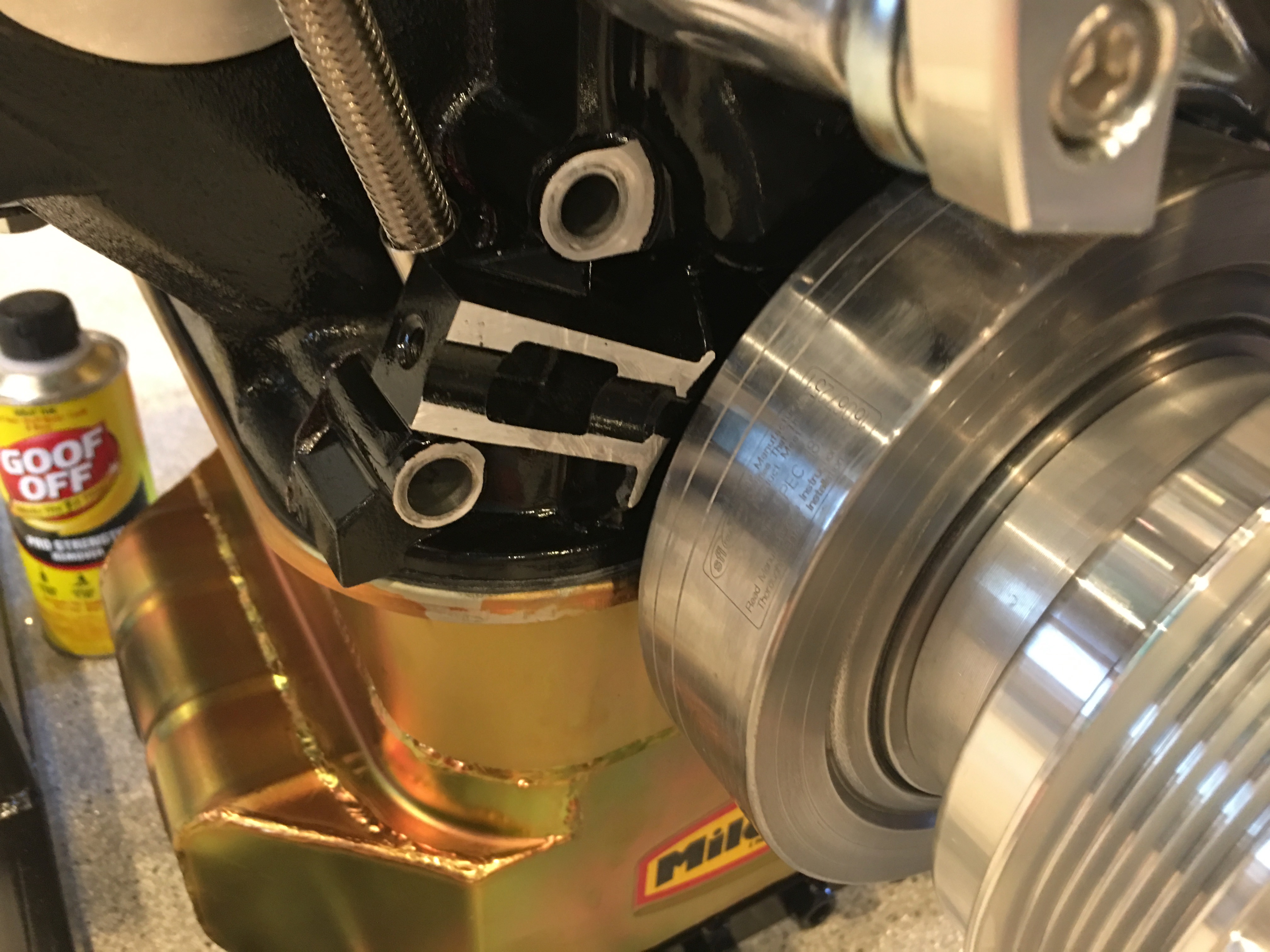
After touching up the paint, I installed the pointer and aligned it with the 0º mark.

Distributor Gear and Parts Fabrication

I need to swap the distributor gear to be compatible with the cam gear. After driving the roll pin out, I used the TechShop’s arbor press to press the gear off.

I had to use some scrap metal to shim the bolster plate up high enough to give me clearance to press the shaft down. I also had to remove the rotor and upper housing to allow the distributor to fit between the legs of the press.

With the old gear pressed off, I needed to drill the new gear to match. I set up a duplicating rig on the mill.

Four clamps around the side precisely locate a v-block in the vise.

The shaft of the gear sits in the groove of the v-block and is clamped against the forward face of the vise using a couple of clamping nuts. The critical reference measurement on the gear placement is from the lower face of the gear (the one clamped to the forward face of the vice), so this arrangement will make the hole the exact same distance from that face. I adjusted the table so that the 1/8″ bit would slide all the way through the old hole without any side load. I then loosened the vise and swapped in the new gear.

The new gear is on the right and the hole turned out perfect. All that’s left is to press the new gear onto the shaft and somehow figure out how to align the holes. If I can’t get the holes aligned, I can always press it on 90º off from the existing hole and drill a new hole through the shaft.

Next up is to trim the ignition coil mounting plate. After cutting it to rough size on the band saw, I mounted it in the milling machine vise. I used some shims to mount it at an angle since the mounting legs are asymmetric.

After machining and some finish sanding, I polished it up a bit on the scotchbrite wheel. After I drill the mounting holes and confirm the fit, I’ll polish this until it’s as shiny as the water pump.

Finally, I cut the electric power steering mount apart so that I can reweld it at the proper angle.

I sanded off all of the welds and cleaned up the edges.

The channel hung over the 3/4″ tubing by just over 1/8″, so I machined off the flanges to align with the face of the 3/4″ tubing when welded.

Steering and Ignition Coil

The first step in installing the electric power steering (EPS) system is to cut the steering shaft. I ended up moving the electric motor back almost as far as it could go and then taking some measurements from the engine mount to ensure I’ll have plenty of clearance.

I just started with a single cut in the shaft because this would let me adjust the motor up or down from there, but it looks like this spot will work absolutely perfectly. I really can’t go back any further because I’d hit the steering shaft u-joint and I’d interfere with the exhaust headers which exit just aft of here.

After determining everything will fit nicely, I cut the other end of the shaft and test fit everything.

The bracket that came with the system isn’t welded at the right angle to allow the motor bracket to bolt up to it. I’ll let Erik know, but I’ll probably just cut and reweld this myself.

The motor clears the F panel by over 1/8″. This bracket isn’t used in this application, so I may just cut it off.

After hunting around for a good place to mount the EPS controller, I decided to mount it to the 3/4″ tubing behind the steering shaft. There’s nearly 1/4″ of clearance between the shaft and the controller, and it’s really out of the way here. The challenge is that there are only two threaded bosses on the EPS controller and they’re at an odd angle. I need to be able to access the screws later in case the controller needs to come out. Mounting it here lets me fabricate a simple bent steel bracket and easily access the mounting screws if necessary.

I ended up deciding to mount the ignition coil to a custom bracket that will bolt to the front of the water pump. I had a piece of scrap aluminum angle, so I took some measurements and laid out the shape of the bracket.

Once I cut out the bracket, it will bolt to the front of the water pump using these two bolts. This should clear everything around it and provide a nice, short run from the coil to the distributor.

Steering and Fuel Tank

I started installing the steering system by installing the bearing block in the firewall and slipping the steering shaft up through it.

I then installed the steering rack into the front of the chassis. The brackets needed some bending to allow the mounting lugs to fit and the elongated hole on the left side (right in this picture) needed to be elongated further on the front bracket to allow the rack to slide far enough to the left to get the right bolt installed.

I installed the upper pillow block and slipped the upper steering shaft through and into the lower shaft to lock in the final position.

I ordered an electric power steering system from Erik Hansen on the FFR forum. After grinding and filing the bracket on the left to fit over the 3/4″ tube, I test fit it along with the bracket on the right until it’s roughly centered around the shaft. The instructions specify how far down the steering shaft it should be installed, but that puts the bracket quite a bit farther forward than this. Ordinarily, that wouldn’t be a problem, but the fat tire F panel will interfere with the bracket as well as the motor if I move it farther forward (I might even need to move it farther back from here)

Here’s the motor that will be installed inline with the steering shaft. I need to confirm that moving it back this much won’t cause any interference with the engine, but I think it will be fine.

I’ve been looking for a spot to mount the remote reservoirs for our quad-adjustable shocks, but I was concerned that the fuel tank will limit accessibility. I figured the easiest way to make sure was to just install the tank. Before doing so, I installed the fuel level sender in the center of the tank.

I also installed the vent at the highest point in the tank.

Finally, I installed the tank in the car.

Getting the tank up high enough to start the bolts required bending the flanges down where the tank sits against the bottom of the square tubing. Finally, I zip tied the vent tubing to the 3/4″ tubing, running it up and over to the left side of the car (though I’m not sure if this will be the final routing).

Pedals and Strut Spacers

I finished adjusting the brake balance bar and adjusted the brake pedal to stop just before hitting the 3/4″ square tube at the top of the picture. Afterward, I adjusted the clutch pedal resting position to be aligned with the brake pedal. I ended up having to cut off about 1/4″ of the threaded shafts on all three master cylinders in order to position the pedals correctly.

After finishing the brake and clutch pedals, I installed the accelerator pedal to the bracket at the front of the foot box. I adjusted the brake and clutch pedal pads to get maximum width and roughly center the brake pedal.

Finally, I installed all of the spacers that I machined last night. Everything fit perfectly, but most of them were pretty tight. Once the spacers and chassis are powder coated, I’m not going to be able to get them in without trimming them a little bit, but that can wait until everything comes apart.

Turned Spacers for Struts and Alternator

I needed to make custom length spacers for the struts and alternator mount, so I stopped by the TechShop after dinner to turn them on the lathe. I ordered a 2″ spacer from March Performance that is already powdercoated, so I wrapped it with some tape to protect the finish. I turned this down to 1.745″

I need spacers of a bunch of different lengths for the struts. I picked up some 0.509″ ID tubing with 0.058″ wall thickness from McMaster Carr and rough cut them on the chop saw about 0.100″ long. I then turned down each end to make them perfectly square and the right length.

Trimming the spacers leaves a burr on the inner edge, so I repositioned the cutter and trimmed it off of each end of all of the spacers.

Here are the finished spacers. I’ll powdercoat these when the car comes completely apart for chassis finishing, but for now I’m going to install these bare.

Afer I got home, I installed the alternator spacer.

I installed it along with the oil dipstick tube. The bottom of the tube is installed with a little bit of black RTV to prevent oil leaks.

New Rear Shocks and Sway Bars

We got back from AirVenture yesterday and our new shocks had arrived along with the extended eyelets. The eyelets just unscrew from the shock shafts and the new ones thread on.

I really like how the QA1 shocks have easily serviceable components. The bearings in the eyelets are held in with snap rings, so they can easily be moved from the old eyelets to the new ones. If they ever need to be replaced in the future, it can be done without replacing the entire shock.

Since I had the eyelets off, I installed the bump stops onto the shafts.

I couldn’t find any instructions that indicate which direction these should face, but they seemed to fit in the upper spring seat better in this orientation.

With the extended eyelets installed, I could mount these in the upper mounting hole.

I still need to mount the upper end of the shock slightly off center to have the spring seat be centered in the bracket.

The upper mounting hole pushes the shock slightly outboard, so the spring now clears the rectangular tubing. Other than fine tuning the spring rates, I think these shocks will work great now. With everything test fit, I measured for all of the spacers. Unfortunately, the spacers they shipped in the kit aren’t sufficient for fabricating all of the ones I need. I ordered some tubing from McMaster-Carr and will fabricate those soon.

With the shocks installed, I started working on the sway bars. The rod end bearings are too long and need to be cut down until only 1/2″ of threads remain.

After trimming both the male and female rod end bearings for the front sway bars, they’re threaded together until they’re basically bottomed out and the bearings are 90º apart.

I installed the front sway bar to the mounting bracket.

The ends of the sway bars are attached to the bottom of the shock mounts through the rod end bearings. The spacer seems too long here, but the bottom of the shock moves outboard as the suspension compresses. The rod end bearings should be basically straight up and down when the suspension is at ride height.

The rear sway bar mounts to a pair of brackets that are bolted to the chassis using the same bolts that hold the toe arms and the forward end of the lower control arms. I really wish I had realized this when we did the initial assembly of the rear suspension.

Once the bracket is bolted on, the sway bar can be bolted to it.

The other end of the sway bar is bolted to the lower control arm through a pair of rod end bearings. I need to fabricate some spacers to take up the extra space between the mounting ears.

Swapping Rear Struts

I spoke with the engineer at QA1 about the fit in the back and we decided to swap the D4501 shocks for D4401 shocks. The D4401 is 1.5″ shorter and only has 3.875″ of travel (vs. 5.25″ on the D4501). To move the shock up to the upper mounting hole, we’re going to swap the upper eyelet for a 9036-196 which has an extra 1″ of length. Since the upper hole is exactly 1″ higher than the lower hole, this will end up leaving the upper spring seat exactly where it is in the picture below.

This will also mean that the ride height adjustment nut will be near the bottom of the adjustment range using the same spring. To correct this, we’re going to swap the 10HT250 (10″) spring for a 9HT250 (9″) spring. This should put the adjustment nut closer to the middle of the adjustment range at the recommended ride height.

I also measured for the spacers we’ll need on the front shocks. The eyelets are wider on the QA1 shocks than the Konis that come with the kit, so I’ll need to make custom length spacers to center the shocks in the mounting brackets.

Test Fit Struts

Our struts arrived from QA1 today. I’ve been concerned with the fitment since there’s so little space on the Mk4 for struts; especially in the back. I’m not installing these permanently now, but I did want to test fit them in case I needed to order any parts from QA1.

The shock body has adjustment knobs for low and high-speed rebound force.

The remote reservoir has adjustment knobs for low and high-speed compression force. All four knobs have 18 settings for force. The remote reservoir also has a Schrader valve for adjusting nitrogen pressure. This should give us nearly infinite adjustability in our suspension.

I test fit one of the rear units on the car. I positioned the shock with the body down and the adjustment knobs to the inside to make it easy to reach them.

I’m not sure yet where we’ll mount the remote reservoirs. One option is to fabricate a bracket behind the rear diff mounting structure and install them there. In this position, it should be fairly straightforward to adjust the knobs, but I won’t know for sure until the tank is mounted.

The engineer at QA1 wanted me to use the upper strut mounting point in the rear, but there’s no way that will work with these stock eyelets; I’ll check with QA1 to see if there are other options. Even in the lower hole, I need to bias the strut forward on the car to keep the spring seat from contacting the bracket.Using one of the long spacers in the kit (about 1.085″) was just about perfect for positioning the strut so that the spring seat is centered in the bracket.

Unfortunately, the spring does contact the chassis member the upper bracket is welded to.

The fronts went on much easier. The engineer at QA1 wants me to use the lower holes in the front and there were no clearance issues with doing so.

With the suspension at full extension, the knobs just touch the bracket on the lower control arm. I may relieve this slightly, but they shouldn’t ever touch when the suspension is carrying weight.

I’m not sure yet where the front remote reservoir will be mounted. One possibility is to mount it to the chassis member just inboard of the struts. With the length of hose that connects the strut to the remote reservoir, I could even mount these in the engine compartment somewhere.

Ordered Struts and Painted Cylinder Head Lettering

I talked to FFR this morning and they confirmed that I could use either the upper or lower strut mounting positions. They offer two because the single and double adjustable shocks they include in the kit aren’t the same length. With the chassis at ride height, I measured the resting length for the front and rear struts using both the upper and lower mounting positions. I also measured the strut and spindle mounting distances on the lower control arms to compute the motion ratio. This gives me all of the information I need to compute the correct strut length, but I still need to decide on spring rates. FFR recommends 500lbs in the front and 350lbs in the rear, but from what I can tell, part of the reason for such high rates is that the Koni struts they include in the kit have very little remaining travel at the normal ride height and the high spring rates help prevent the struts from bottoming out. The QA1 struts have a greater range of travel, so I shouldn’t need quite as high spring rates. After a bunch of research, we decided that we’d start with 400lbs in the front and 250lbs in the rear. I’m assuming we’ll end up ordering additional springs when we’re dialing in the suspension down the road.

I spoke with one of the engineers at QA1 and gave him the dimensions I measured and spring rates. He recommended the following items:

  • D4501 quad-adjustable shocks, front and back. These have a travel of 11.625” – 16.875”.
  • 10HT400 springs, front. These are 10″ long; 12″ long springs would work, but they would put the ride height adjustment nut at the very bottom.
  • 10HT250 springs, rear.

He also recommended using the lower mounting holes on the front and the upper on the back which only have a 1/8″ difference in resting length. These items are all on order, so I should be able to confirm they fit some time next week.

With the measurements complete, I put the chassis back on the dolly.

One last thing I’ve been wanted to do before engine assembly is to paint the engravings at the end of the cylinder heads. I tried this earlier and ended up wiping off the paint because it wasn’t looking great. I tried a new technique tonight which worked much better. I cleaned the engravings thoroughly and then used a q-tip to apply paint over the engravings thick enough that I couldn’t see them. I then let the paint set up for a couple of hours and then used some solvent to remove everything on the surface. You can still see a haze of paint around the engravings, but that should come off with some more solvent. I didn’t want to go further tonight though since it would be easy to go too far and have the solvent remove the paint from the engravings. I made sure I did opposite ends on the cylinder heads so that if this doesn’t turn out well, I can just put these at the back of the engine and no one will ever see them.