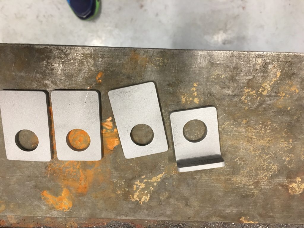
The Factory Five kit has rigid brake lines between the master cylinders and each of the wheel wells. At the wheel well, there is a fitting that transitions between the rigid line and a flexible stainless line that runs out to the caliper. This fitting is held in place with a small bracket. The kit only came with two of the brackets (probably because I deleted the brakes from the kit) and they’re stainless. Since I plan on welding the brackets on, I decided to fabricate four new brackets out of mild steel.
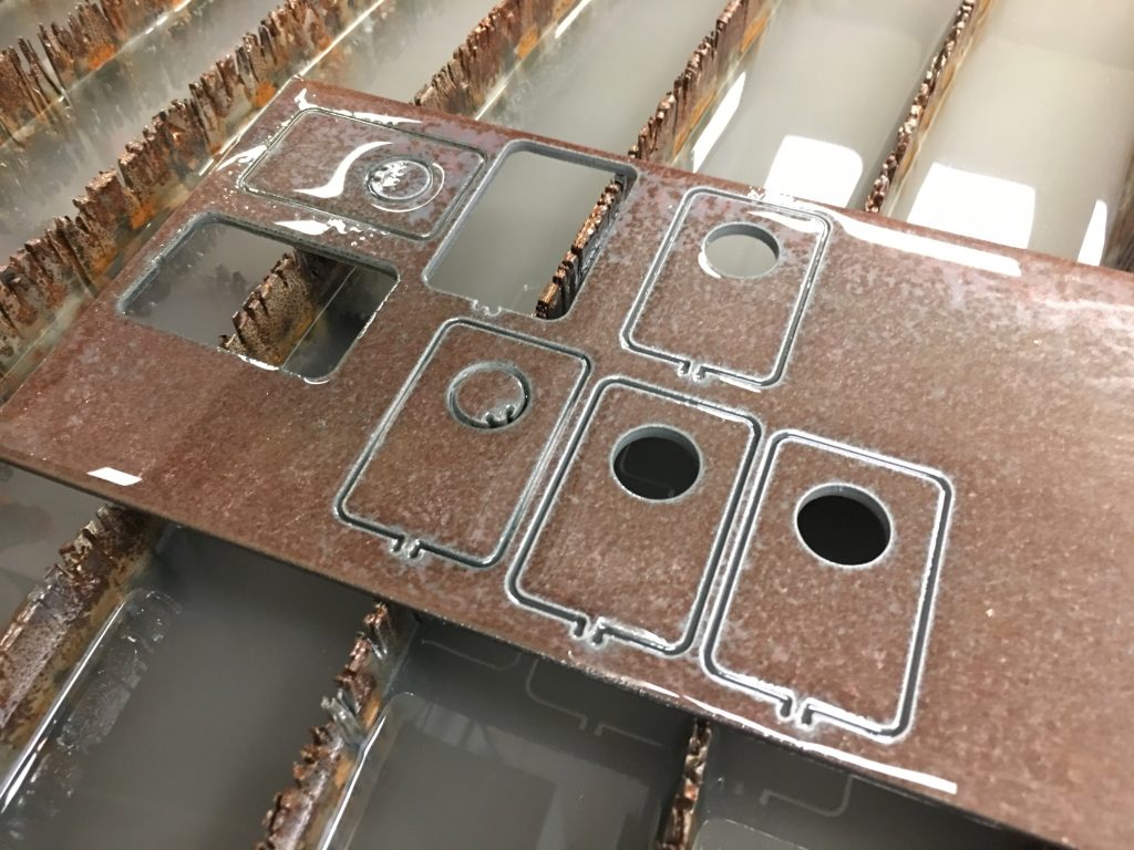
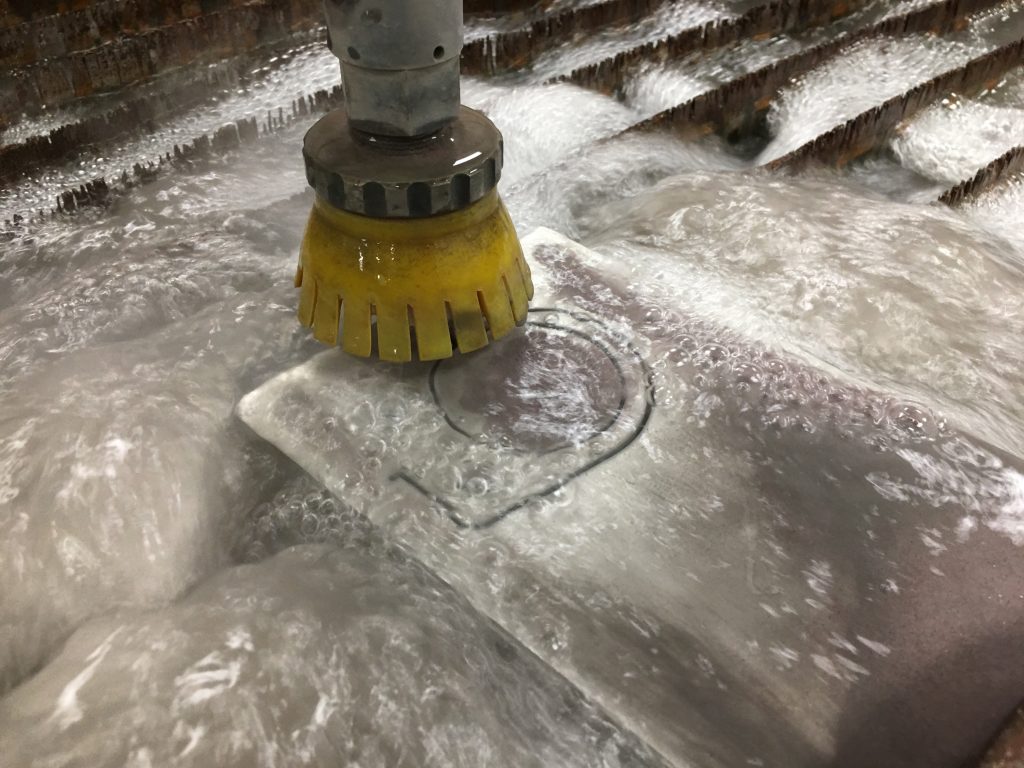
I drew up a simple bracket in Autodesk Mechanical and cut them out on the waterjet. It took a couple of tries with different tab size settings and cut speeds until we got four that we were happy with.
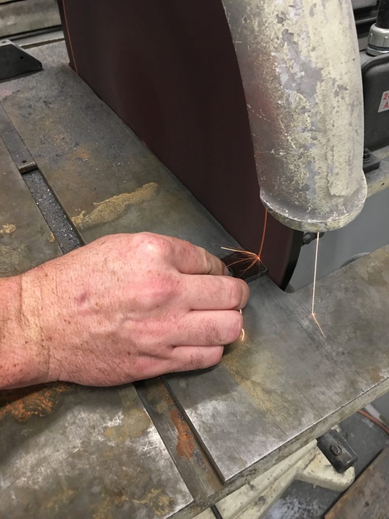
I used the disk grinder to sand off the tab and clean up the edges.
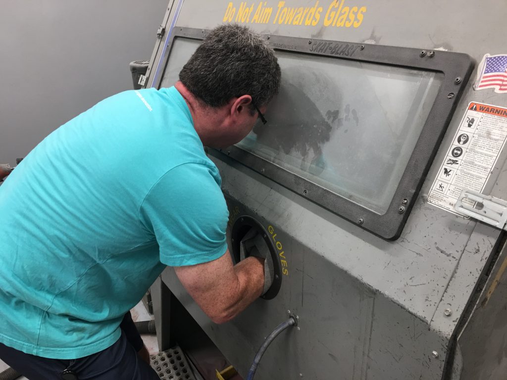
I then sandblasted all the rust off.
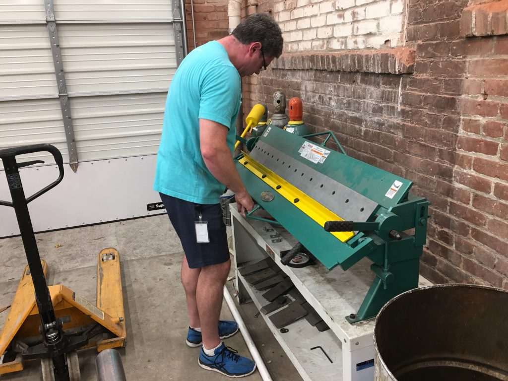
The parts from FFR have a couple of holes and are riveted to the side of the 3/4″ chassis tubing. Instead of riveting ours on, I put a bend in the brackets so that I can weld them to the top of the 3/4″ tubing.
Here’s one of the bent pieces along with the other three that are ready for bending.
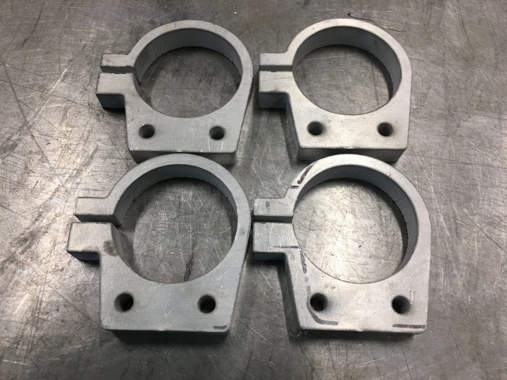
After finishing up the brake fitting brackets, I loaded up the cut path for the bracket I designed to hold the remote strut reservoirs. I’m cutting these out of a piece of 1/2″ 6061 aluminum.
I’m glad I did the brake fitting brackets first since I had plenty of extra steel and could afford to make a couple of mistakes (as I did). For the reservoir brackets, I only had a big enough piece of aluminum to cut the four I need. Fortunately, everything worked perfectly and every piece turned out great.
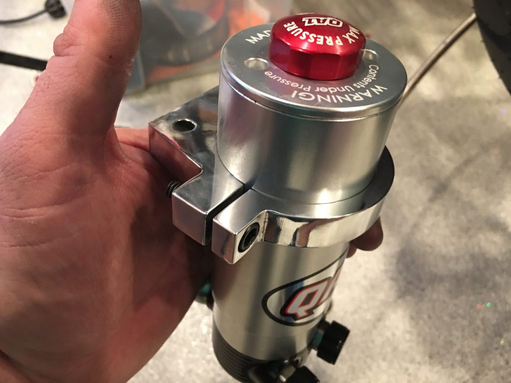
I designed these with a tab on the left that I can use to clamp the bracket tight around the reservoirs. I also cut a couple of 1/4″ holes in these so that they can bolt to a piece of angle steel that I will weld to the chassis.
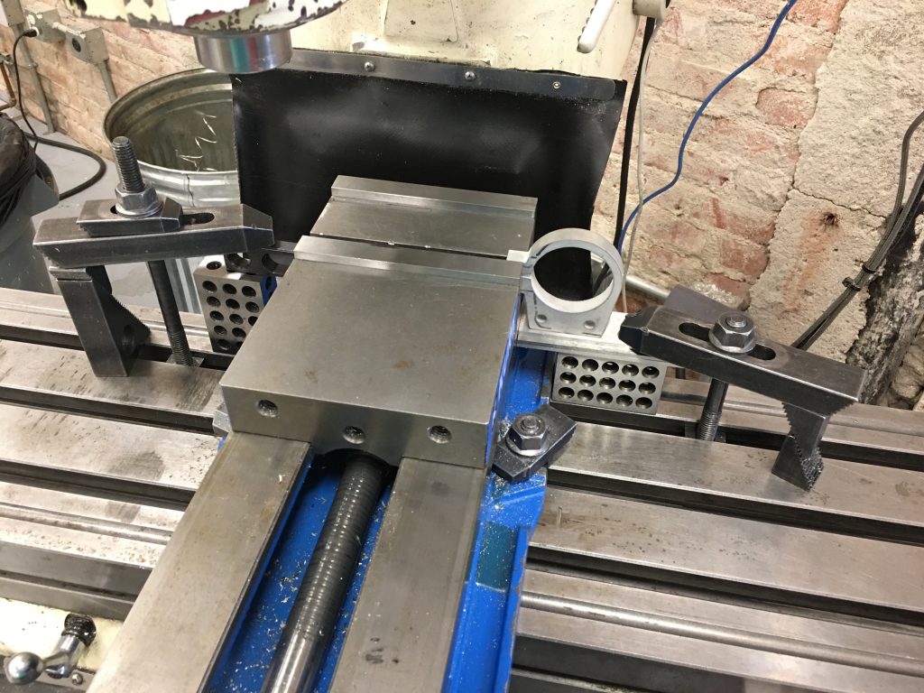
I needed to use several tools to drill the holes in the tabs, so I set up a couple of positioning fixtures to assure every piece is clamped in precisely the same location. The part sits on the fixture on the right to align it with the bed; this assures the hole is exactly perpendicular to the tabs. The fixture on the left provides a hard stop to precisely position the part in the X axis (along the bed). The Y location is fixed by the back of the vise which doesn’t move. The vise clamps both the upper and lower portions of the tabs so that there is no movement in the tabs during machining.
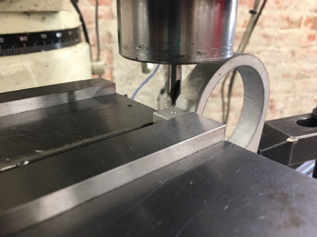
I used a center drill to create a small pilot hole in the center of the tab. I then drilled through both parts of the tab with a #7 bit and then through the upper part of the tab with a 1/4″ bit.
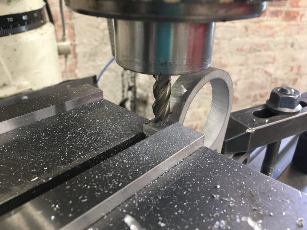
Afterward, I use a 3/8″ end mill to create a recess 0.235″ deep.
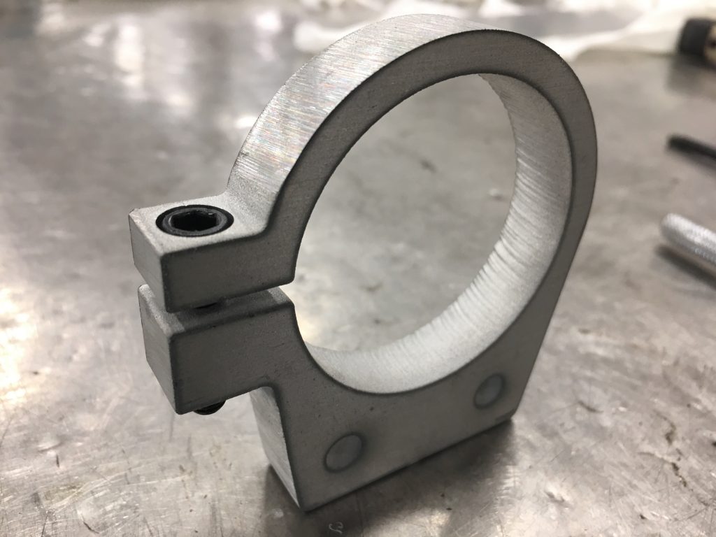
After threading the lower part of the tab with a 1/4-20 tap, I test fit a 1″ socket head bolt. The socket head bolt fits perfectly in the recess and is flush with the top of the tab. The 1″ bolt is a little long, so I’ll probably use a 3/4″ stainless bolt for the final install.
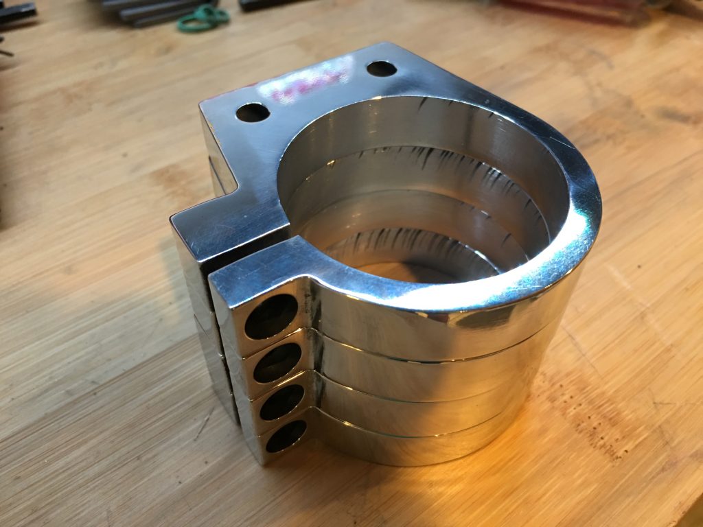
I sanded the edges smooth and used a drum sander to smooth out the inside of the hole until it’s a slip fit over the reservoir. Afterward, I polished the brackets until they are nearly a mirror finish.
The brackets hold the reservoirs perfectly. They slide over the reservoirs with almost no play and clamp tight with only about 1/2 turn on the bolt.

