Removed Firewall

I’m planning on installing a mechanical throttle linkage instead of using a throttle cable. There is a kit available, but plenty of people have fabricated their own. They typically install it to the firewall above the 2″x2″ square tubing, but that requires installing some firewall reinforcement that ties that area to the top of the square tubing. Unfortunately, I’ve already installed some electrical components in this area, so I decided to install it directly onto the 2″x2″ square tubing. To do that, I needed to get the firewall out of the way.

The firewall-to-chassis attachment is the only place on the chassis that I haven’t installed rivnuts, so I’ll do that as well while the firewall is out.

Wrapped Up Brake Line Installation

I laid out and installed all of the brake line supports for the long, straight run along the 4″ chassis tubing. There are four of the mounts with the curved back mounted directly the the 4″ chassis tube.

There are also a couple of mounts attached to the underside of the square tubing under the seat. I didn’t realize until after I took this picture that I had intended to install the spiral brake line guard before flaring the ends. I’ll have to see if the tubing is long enough to remove one of the flares and install the guard. I’d really hate to have to remake the brake line.

After torquing all of the fittings, I filled the fluid reservoirs and started trying to bleed the brakes. I still have more work to do to get all the air out of the system.

Engine is Fixed!!!

My dad stopped by again this morning and we wrapped up the engine assembly. We ran the oil pump for about three minutes with a drill and spun the motor over a few times with the starter (without plugs) to make sure oil was nicely distributed throughout the engine.

The moment of truth arrived and we fired up the motor. Success!!! The motor sounds fantastic. Nice and smooth, and no knocking!

We kept the exhaust pipes outside of the garage to limit the exhaust inside. We pushed the RPM up to about 2,500 and let it run for about 30 minutes to help seat the rings.

After shutting down, we pulled the car back into the garage and put the car back on the dolly. Since we’re still in the middle of our remodel, we likely won’t make much progress on the car over the next few months, but I’m incredibly pleased that this is behind us!

Installed New Piston

My dad and I stopped by Dino’s shop this morning to have him balance our new piston and rod. While our piston was lighter than the old one, we lucked out and the new rod was slightly heavier on the small end. There’s still a small imbalance, but Dino said that it’s more important that the rotating mases are balanced than the reciprocating masses. He also loaned us his tapering ring compressor which makes piston installation far easier than with the traditional ring compressor

We got back to the house and made quick work of getting the piston into the block and installing the bearing cap. We turned the motor over a couple of times to make sure everything was moving smoothly.

We installed the newly painted oil pan, then installed and torqued the heads. I hadn’t yet adjusted the guide plates on the new cylinder head, so we spent a bit of time ensuring that all of the rocker rollers were nicely centered over the valve stems. Finally, we installed the intake manifold and cleaned up the sealant. We can’t run the motor until that sets, so that was a good time to stop for the day.

Painted Oil Pan and New Piston Weight

I cleaned the oil pan and painted four coats of the same Eastwood high-temperature ceramic engine paint that I’ve used on the rest of the engine. I put on some extra coats here because this is likely to take more abuse from road debris than the block or heads.

I received the new piston from Ford Racing (on the right). Unfortunately, it’s 9 grams lighter than the piston it’s replacing. We’ve been told that we need to get the rod/piston assembly within 2 grams, but we’ve also heard that it’s important to get each component as close as possible as well. We’ll check with Dino about whether this will work or we need to order a replacement.

Piston Weight and Oil Pan Prep

Since our connecting rod was slightly twisted, we decided to order a new one. My dad took care of talking to Ford Racing and Scat about exactly which part to order. That led to an interesting conversation about the piston and connecting rod weight. I weighed the existing rod, and Scat manager to find one that is very close. However, they mentioned that it was important to get the combined weight of the connecting rod and piston assembly within 4 grams of the old weight (preferably with 2 grams).

I was concerned that I couldn’t get an accurate weight from the old piston since I ground some of the damage off and additional wear had occurred on the side of the piston. However, when I flipped the piston over, there was a number written on the bottom that looked like it might be the weight.

I weighed the piston and it was significantly heavier than the number written on the bottom. I figured the weight must be without the piston rings, so I removed as much as I could. There was 2-3″ of the top two rings stop stuck in the piston, but this brought the weight down to 439 grams, so 433.5 grams must be the weight of the bare piston.

While I have the oil pan off, I decided to go ahead and paint it black to match the engine. I spent awhile cleaning out the inside and scuffing the outside with a scotchbrite pad.

Pulled #6 Piston

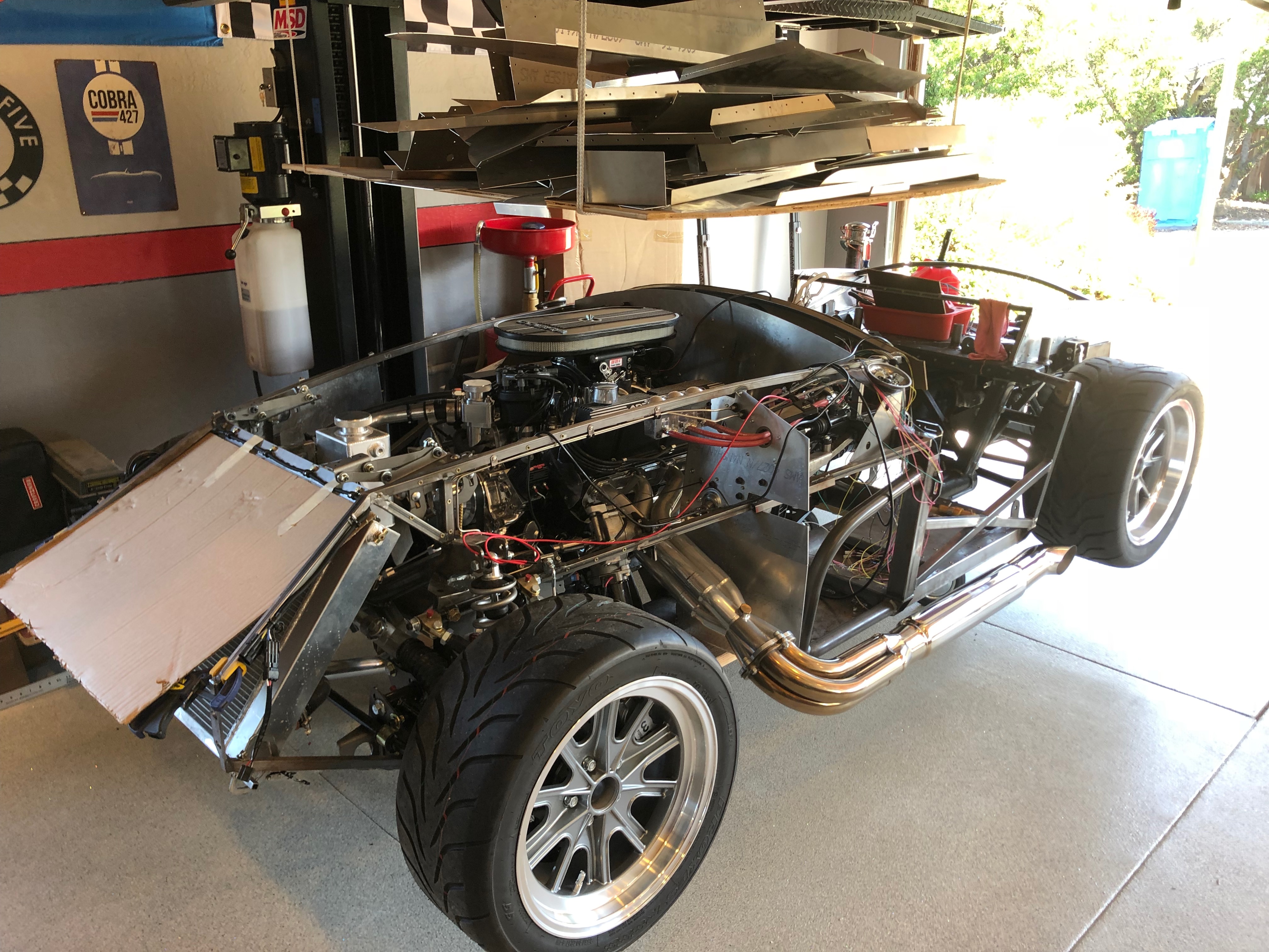
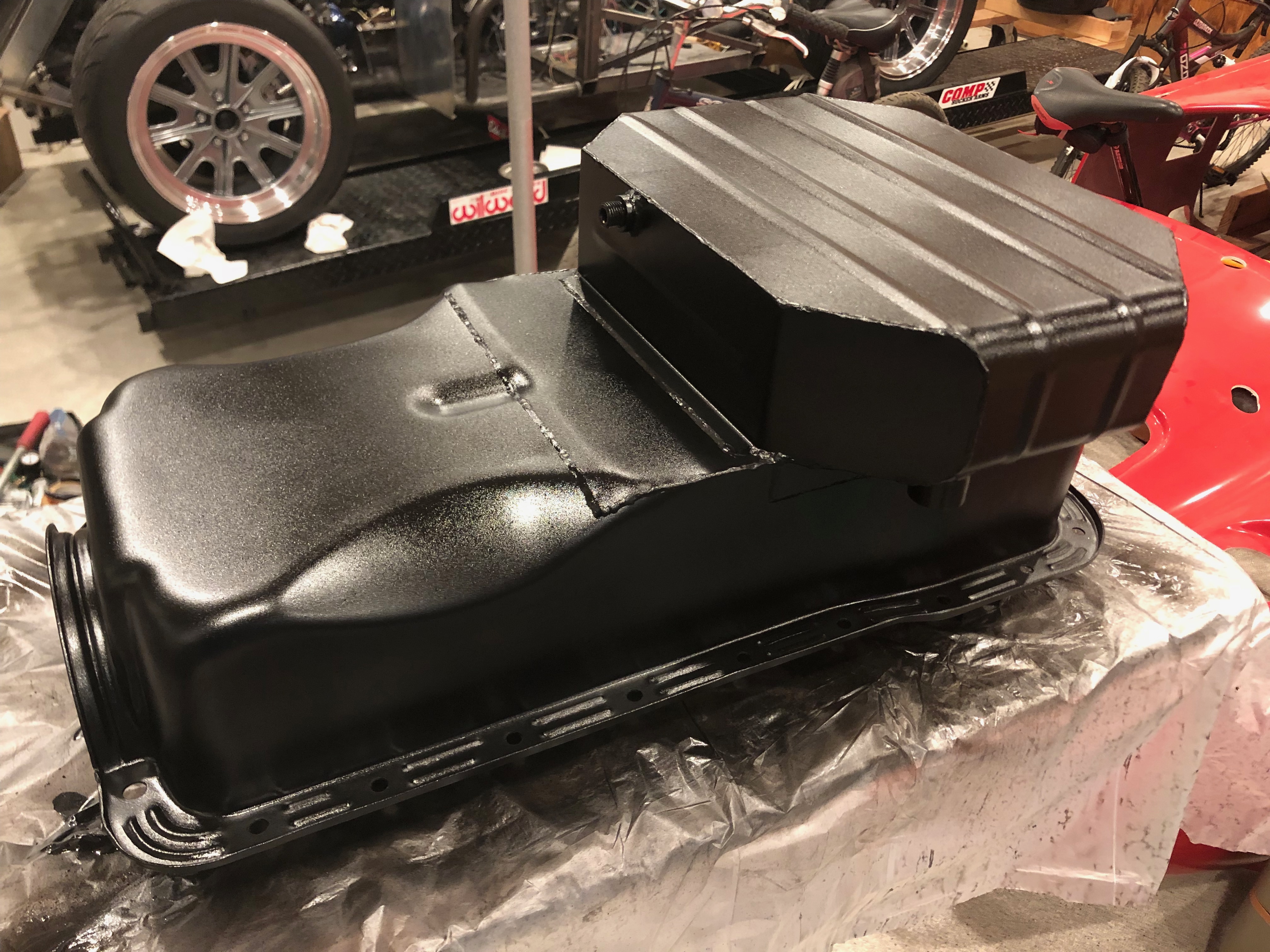
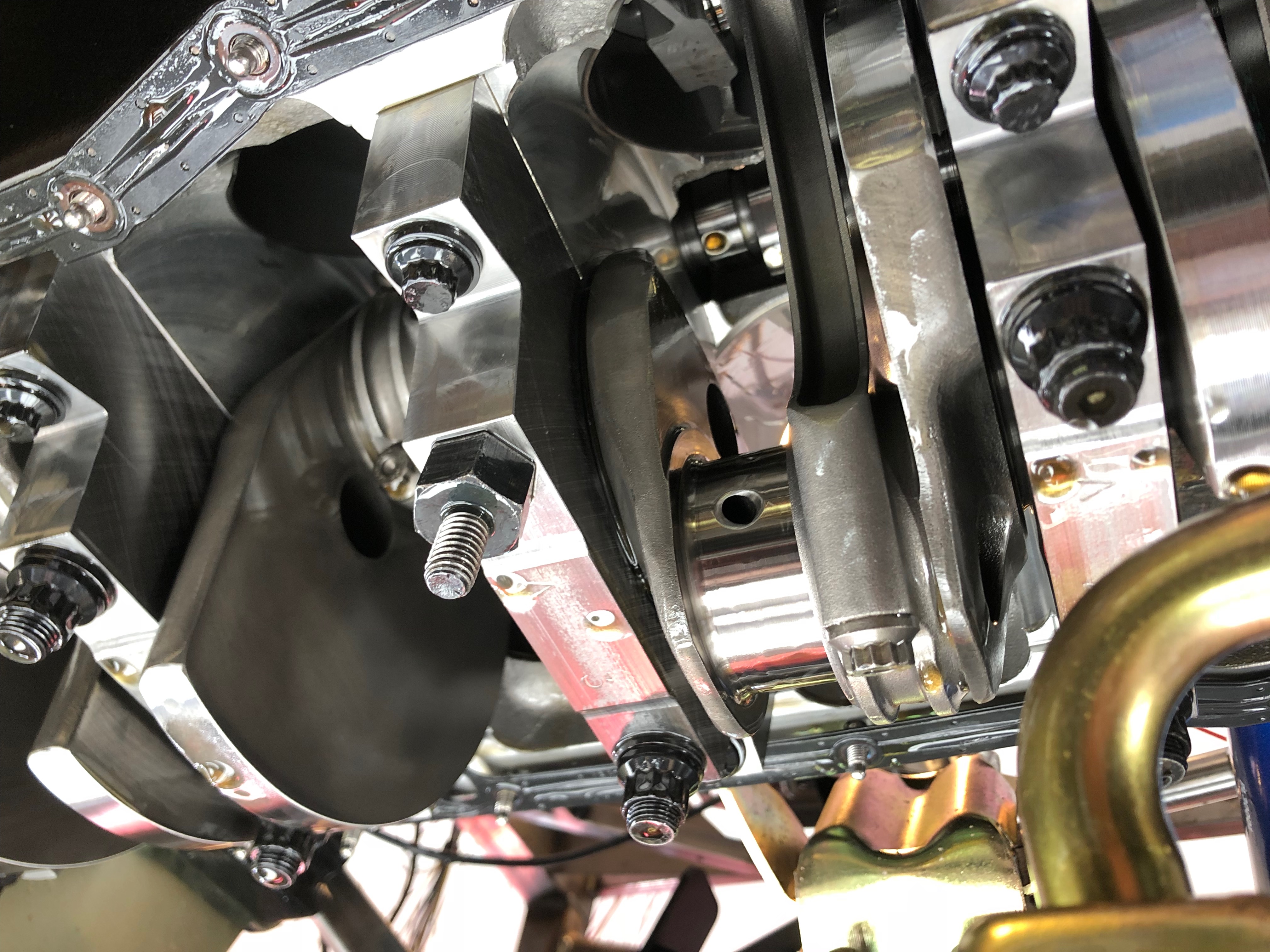
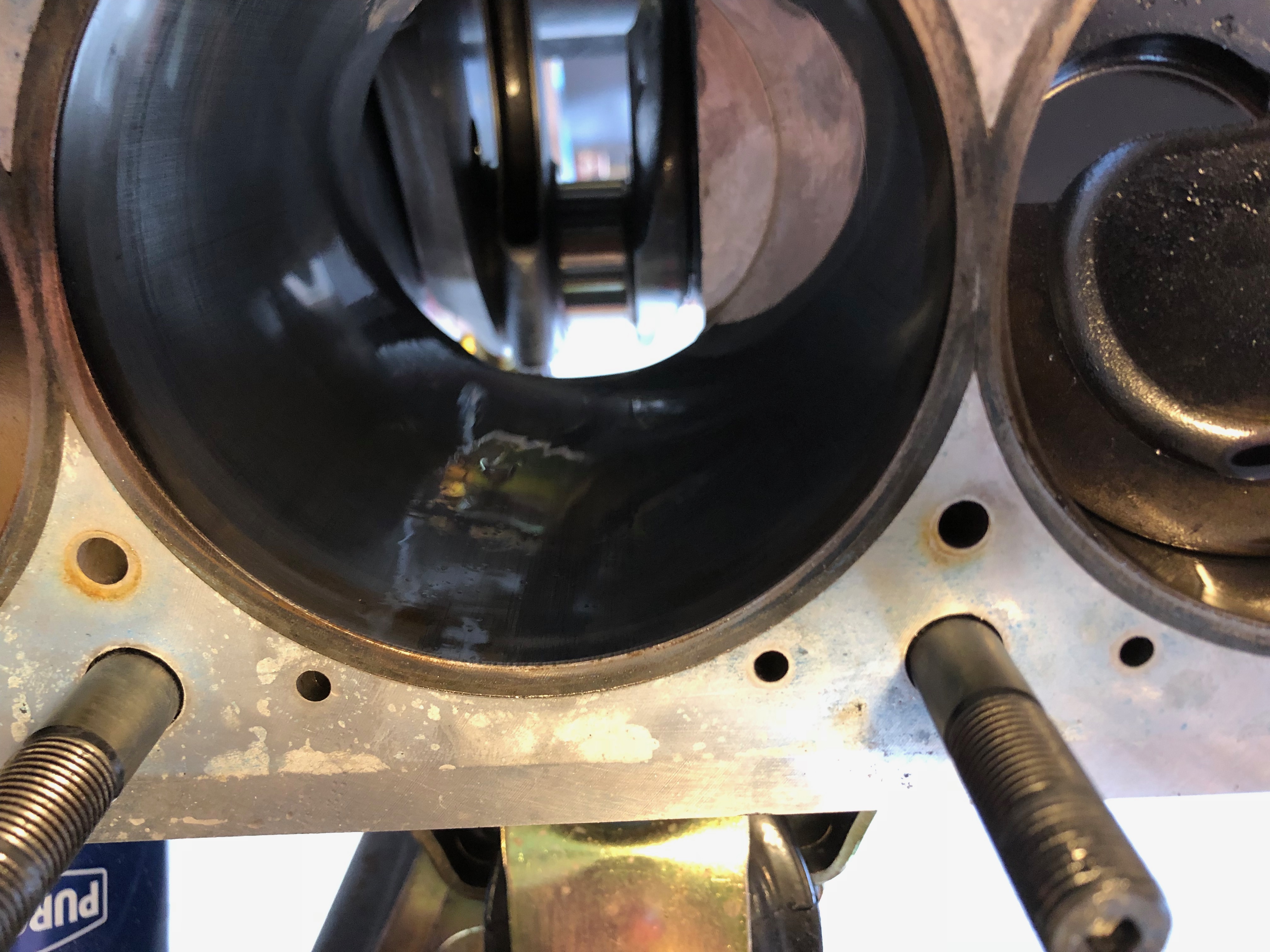
We put the Cobra on the lift and dropped the oil pan. After removing the connecting rod bolts, we removed the bottom of the connecting rod and pushed the piston out of the top of the cylinder.

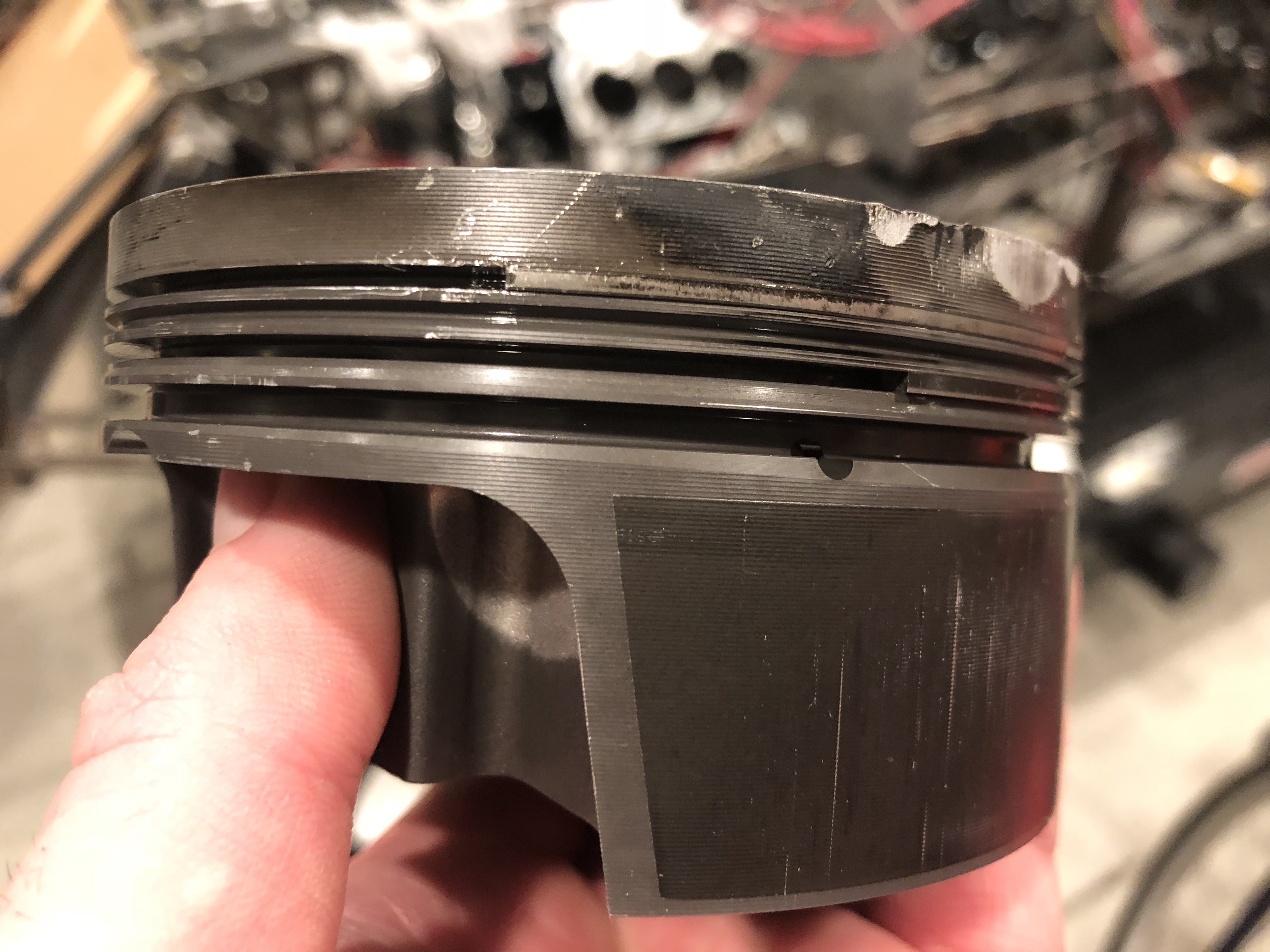
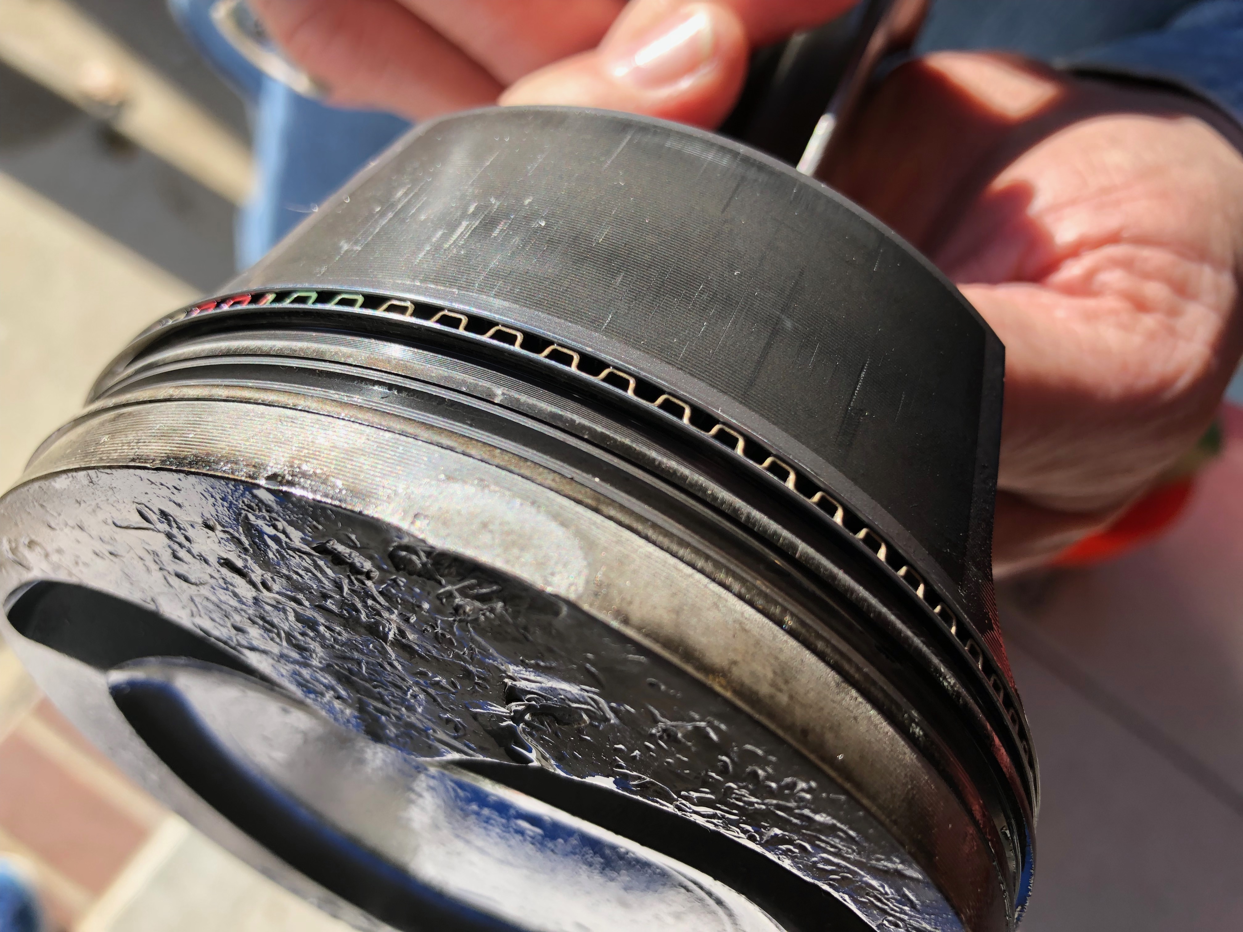
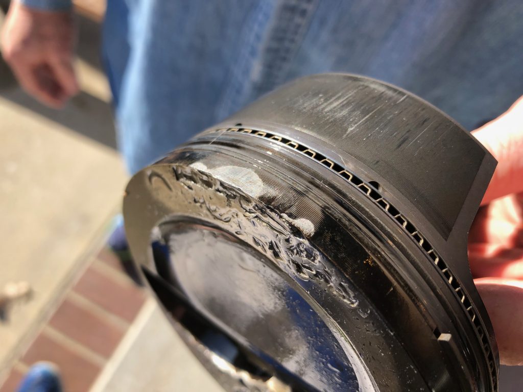
It’s pretty clear that the piston was more damaged that it appeared from the top. This is the bottom edge and it’s pretty well worn above the compression ring. It’s also pretty scored on the skirt. Worse though, both compression rings were pinched in the groooves.

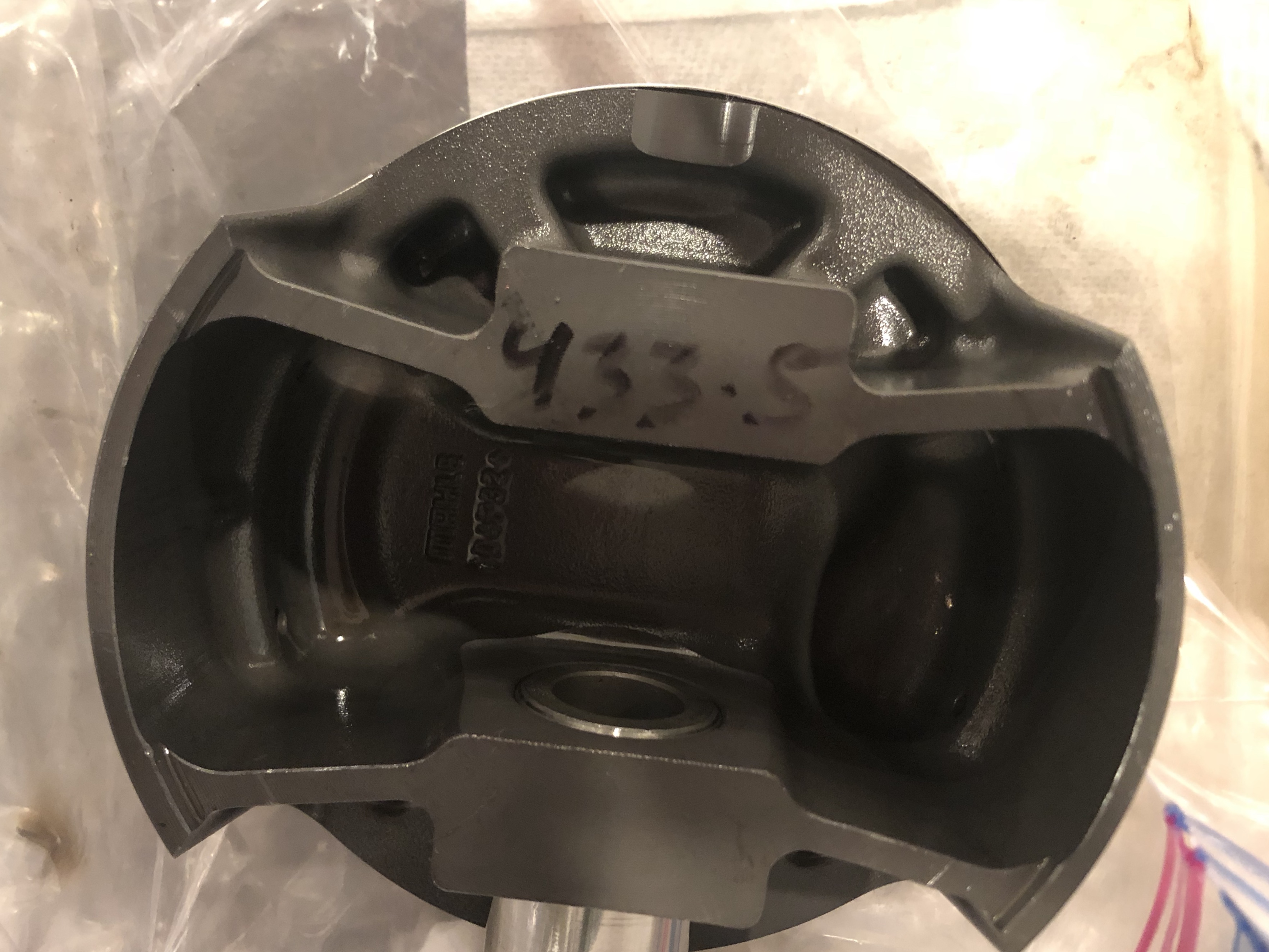
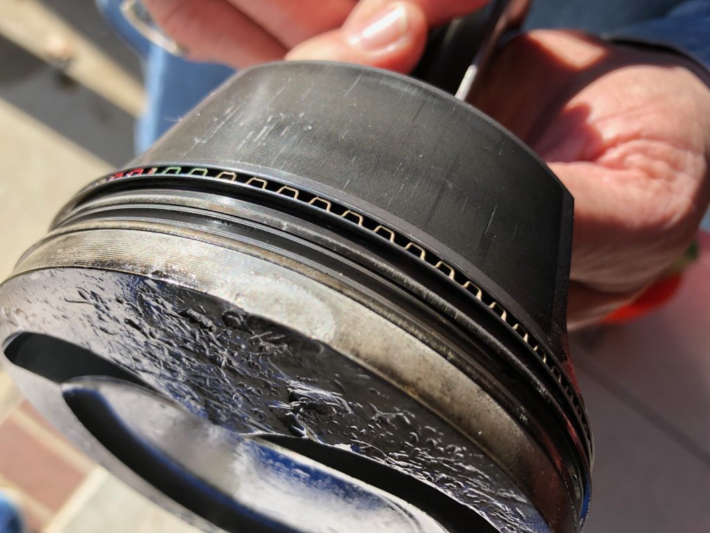
This is the top edge of the piston. You can see wear above the compression rings and scoring on the skirt. The compression rings are also pinched on this side.

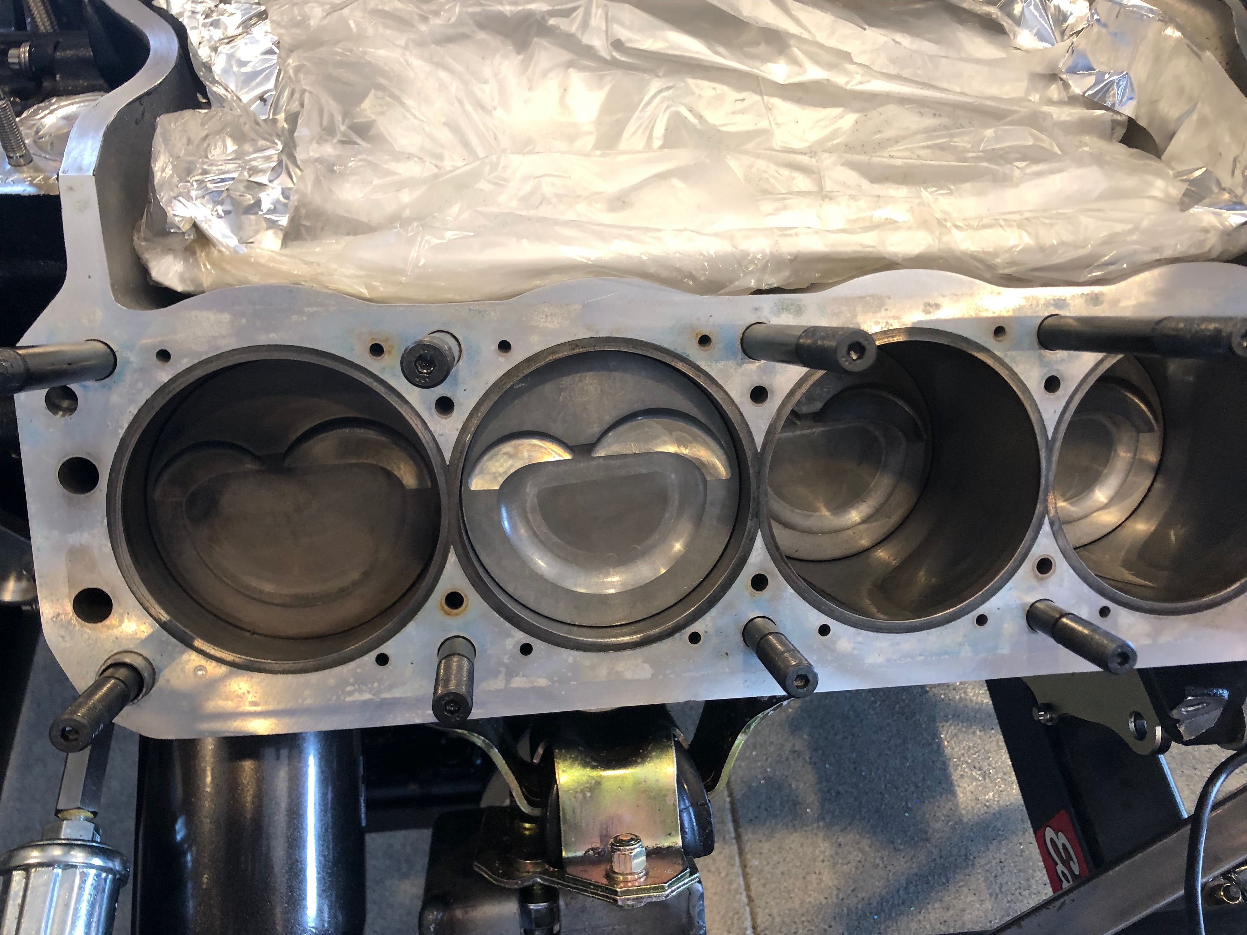
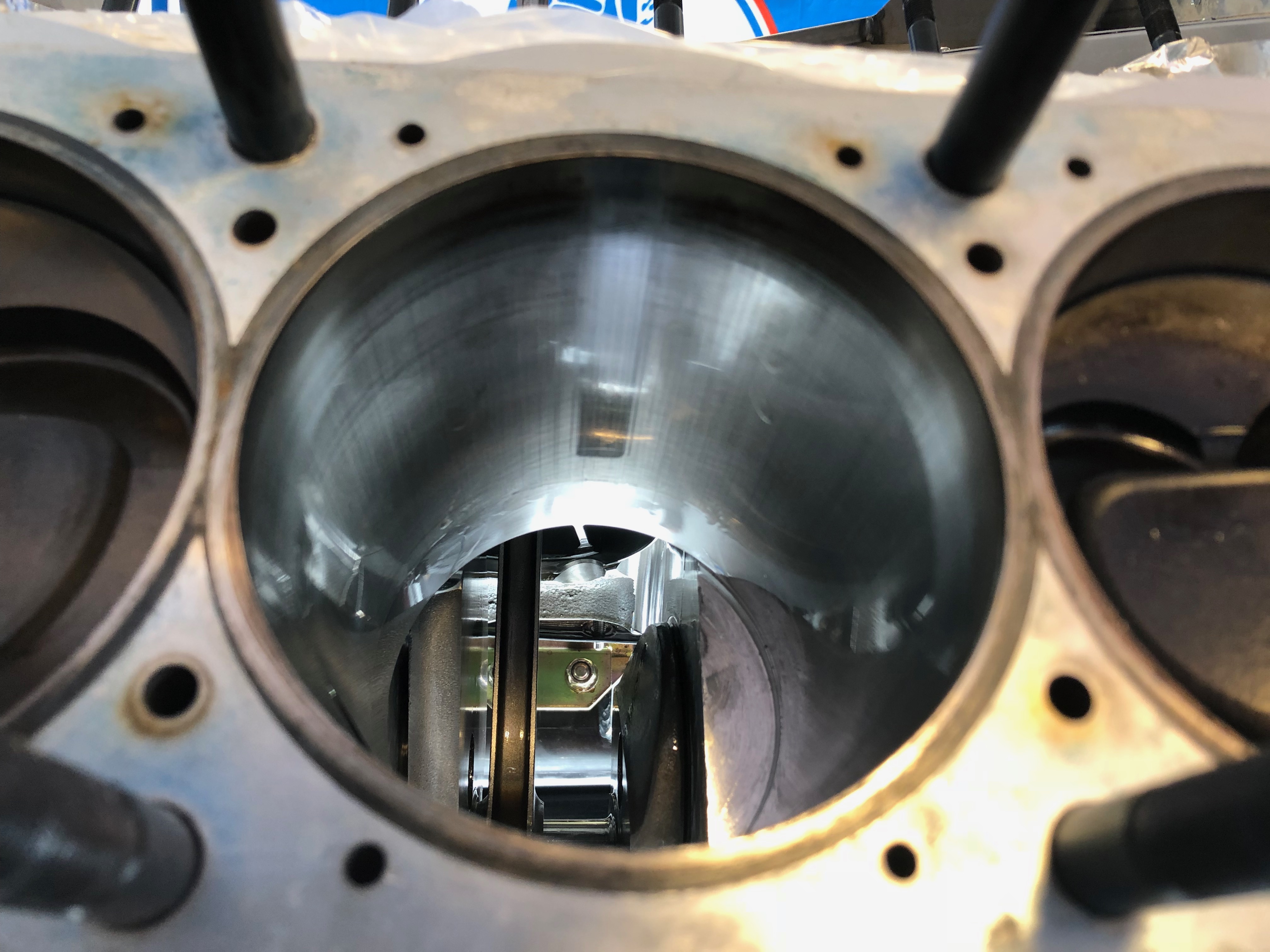
In the area the pistons are worn, there is some polishing of the cylinder wall. You can’t feel this with your fingers, so it’s just some microscopic surface polishing. We’ll need to add the cross-hatching back, but that should be pretty straightforward.

It’s pretty hard to see in this picture, but the lower side of the cylinder has similar polishing, but you can slightly feel the polished area on this side. There are no grooves and I think what you can feel is well less that 0.001″.

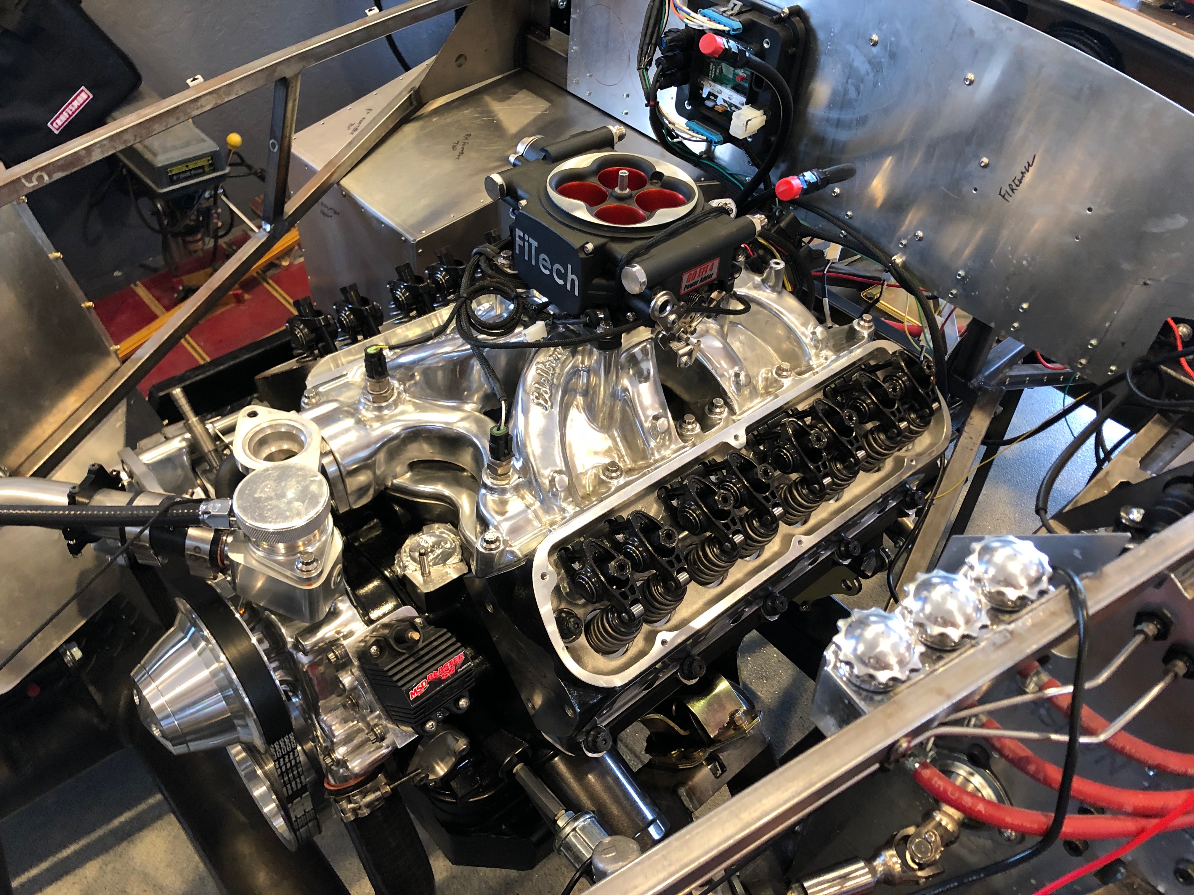
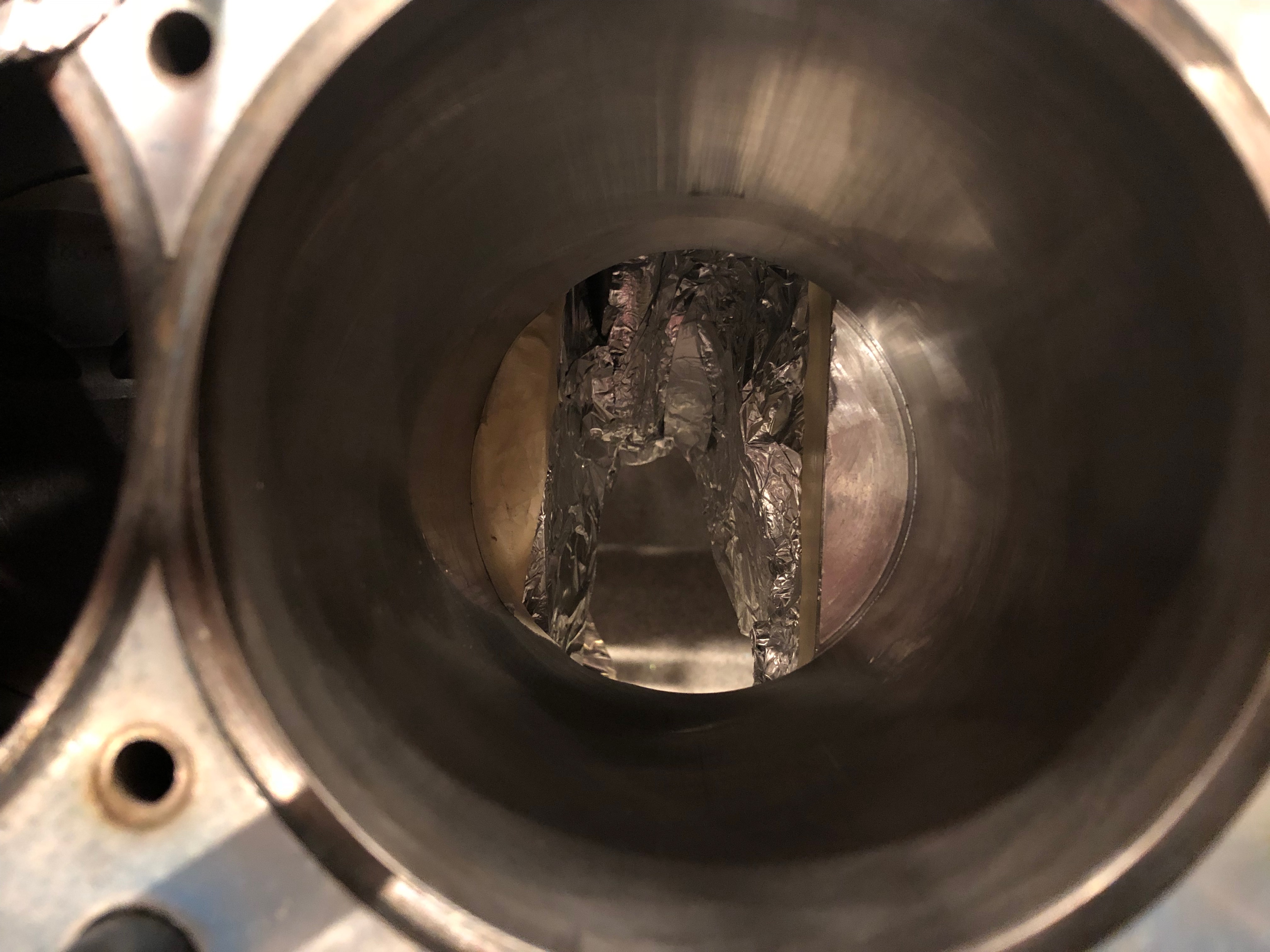
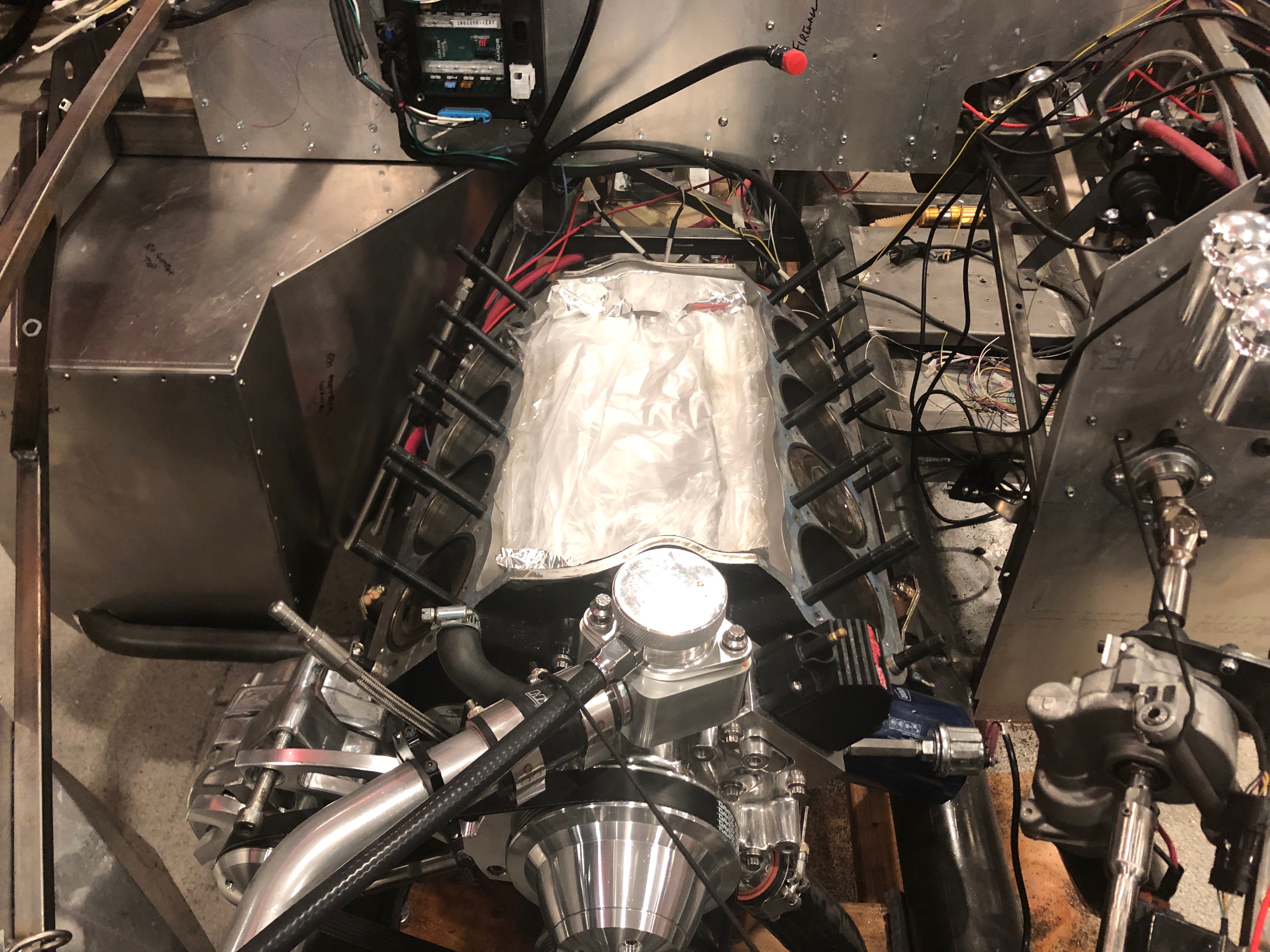
We dropped by Dino’s shop to have him examine the piston and connecting rod. He showed us how to remove the piston and checked the connecting rod for damage. He suggested we use some 400-600 grit sandpapaer to add the crosshatching pattern back to the cylinder wall. I protected the lower end of the engine as well as I could with aluminum foil and masking tape, then used some 400 grit sandpaper soaked in solvent to add the crosshatch pattern back. I made some good progress on the lower side, but I can still feel the polishing area slightly.

Painted Cylinder Head Engraving

After thoroughly cleaning the engravings with some solvent and a toothbrush, I put some of the of the engine paint over the engravings until I couldn’t see them. After letting it set up for a couple of hours, I used a solvent-soaked q-tip to remove most of the excess paint. I didn’t want do too much at this point since the paint is still soft.

After letting the paint cure overnight, I used more solvent-soaked q-tips to remove the rest of the excess paint. This technique works wonderfully and the engraving really pops.

Pulled Remaining Head and Prepped Replacement

Even though we’re essentially certain the heads are fine, we still had one head with known damage from the nut going through the engine. It just turned out not to be on the side where he was adjusting the lifter. Since we had already ordered a replacement head, I could either return that or replace the damaged head. I decided to replace it.

I spent a couple of hours tearing down the right side of the motor tonight until it was at the same place as the left side.

I cleaned and masked the new head, then sprayed several coats of Eastwood’s high-temperature ceramic engine paint in gloss black.