Distributor Gear and Parts Fabrication

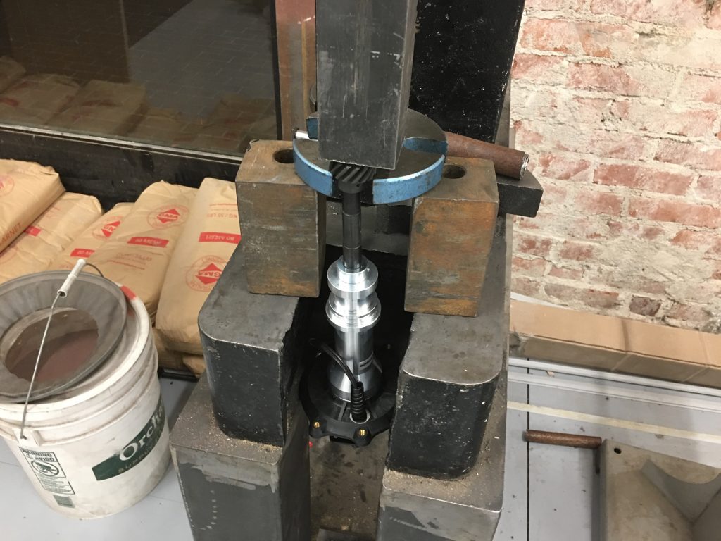
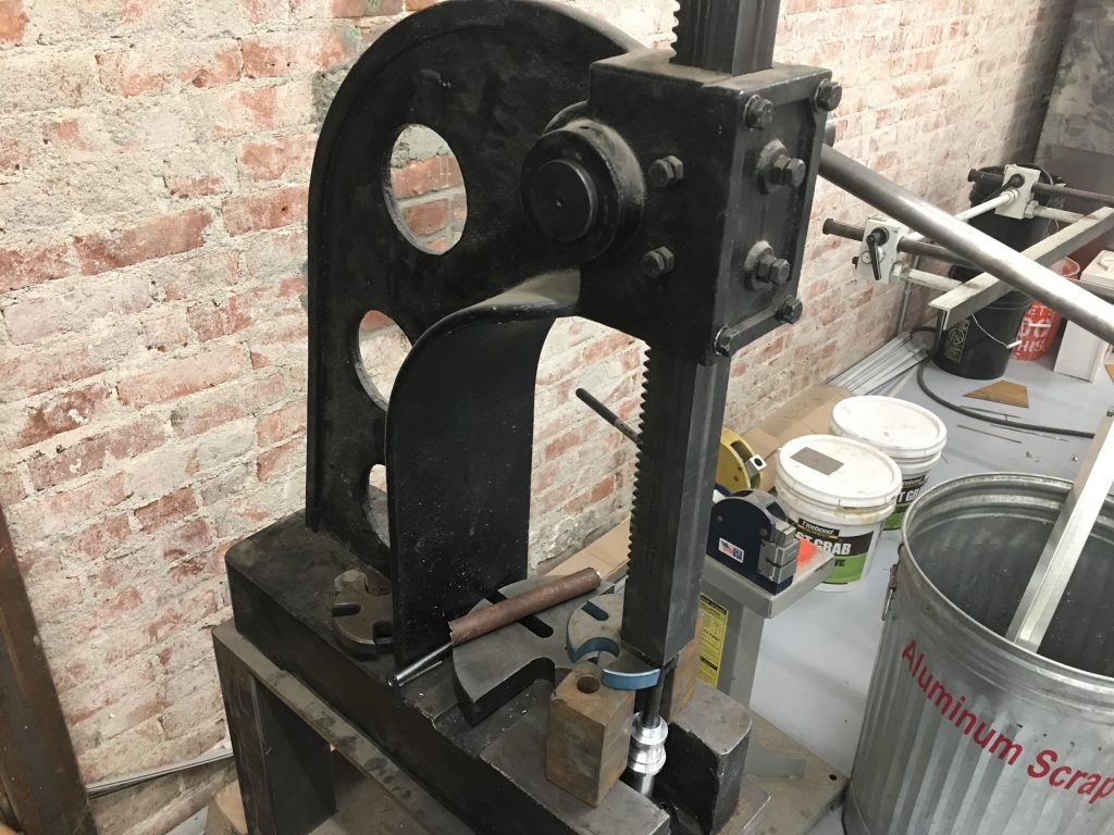
I need to swap the distributor gear to be compatible with the cam gear. After driving the roll pin out, I used the TechShop’s arbor press to press the gear off.

I had to use some scrap metal to shim the bolster plate up high enough to give me clearance to press the shaft down. I also had to remove the rotor and upper housing to allow the distributor to fit between the legs of the press.

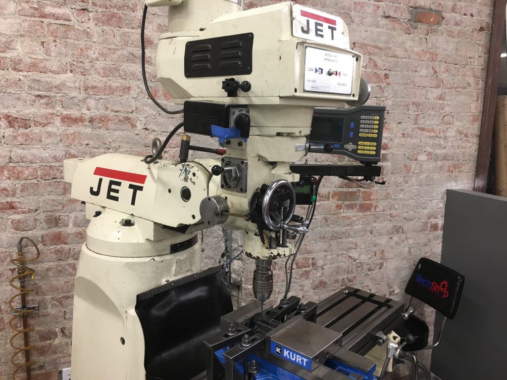
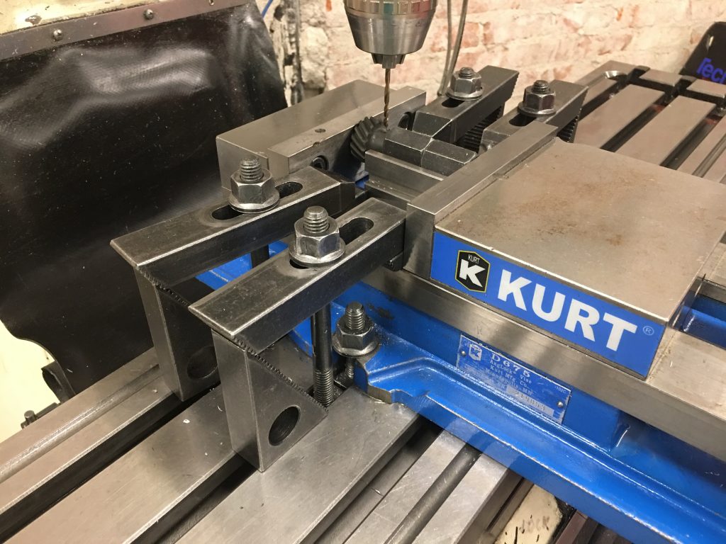
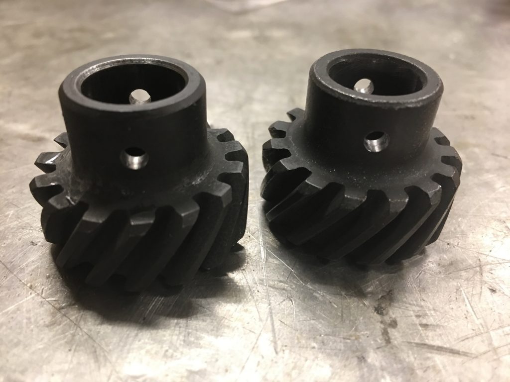
With the old gear pressed off, I needed to drill the new gear to match. I set up a duplicating rig on the mill.

Four clamps around the side precisely locate a v-block in the vise.

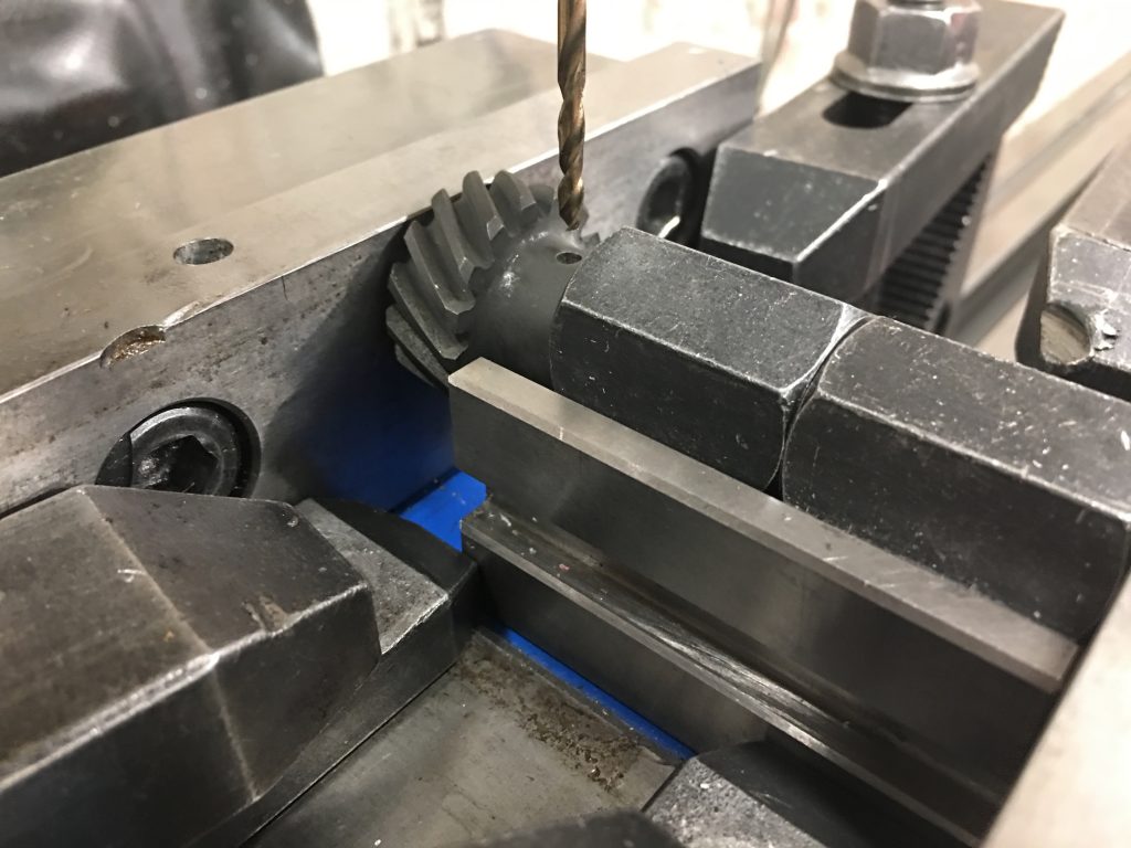
The shaft of the gear sits in the groove of the v-block and is clamped against the forward face of the vise using a couple of clamping nuts. The critical reference measurement on the gear placement is from the lower face of the gear (the one clamped to the forward face of the vice), so this arrangement will make the hole the exact same distance from that face. I adjusted the table so that the 1/8″ bit would slide all the way through the old hole without any side load. I then loosened the vise and swapped in the new gear.

The new gear is on the right and the hole turned out perfect. All that’s left is to press the new gear onto the shaft and somehow figure out how to align the holes. If I can’t get the holes aligned, I can always press it on 90º off from the existing hole and drill a new hole through the shaft.

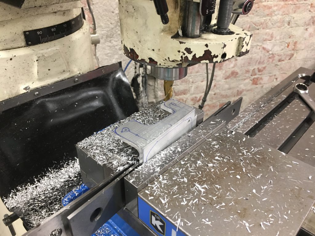
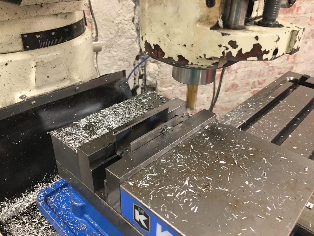
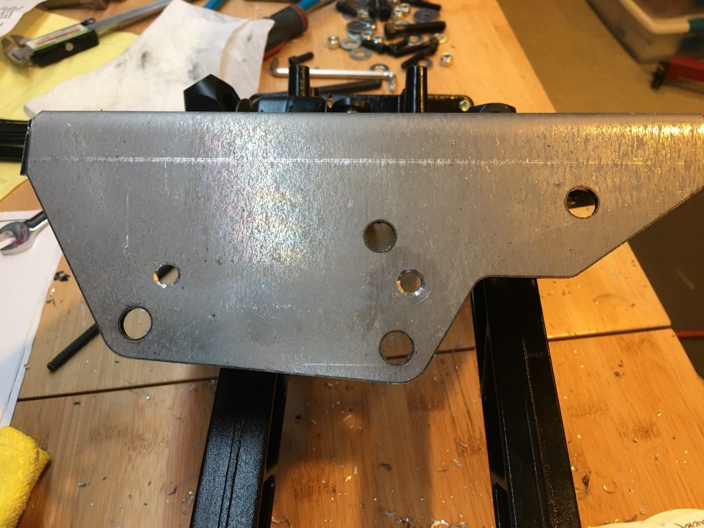
Next up is to trim the ignition coil mounting plate. After cutting it to rough size on the band saw, I mounted it in the milling machine vise. I used some shims to mount it at an angle since the mounting legs are asymmetric.

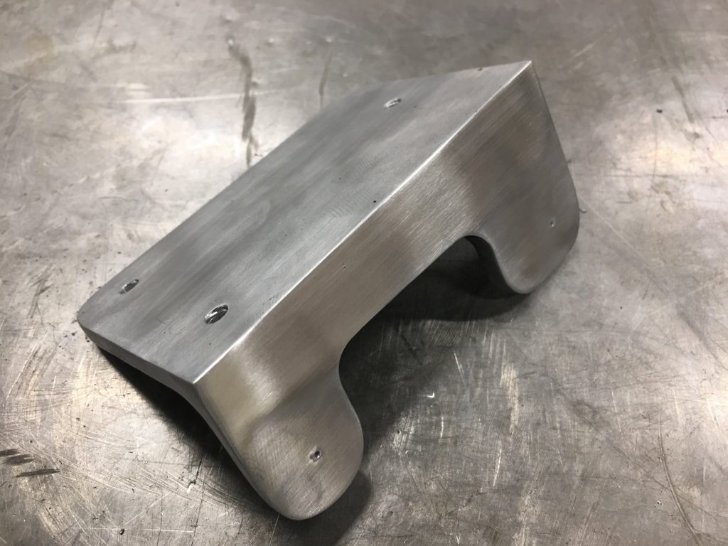
After machining and some finish sanding, I polished it up a bit on the scotchbrite wheel. After I drill the mounting holes and confirm the fit, I’ll polish this until it’s as shiny as the water pump.

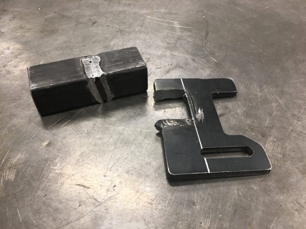
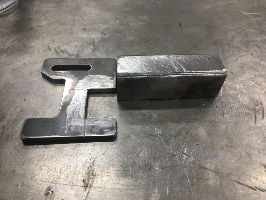
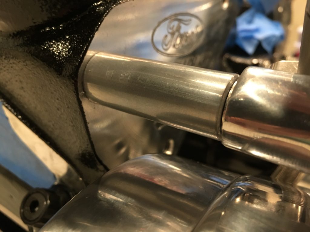
Finally, I cut the electric power steering mount apart so that I can reweld it at the proper angle.

I sanded off all of the welds and cleaned up the edges.

The channel hung over the 3/4″ tubing by just over 1/8″, so I machined off the flanges to align with the face of the 3/4″ tubing when welded.

Steering and Ignition Coil

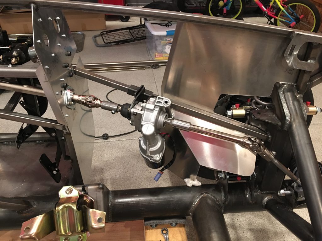
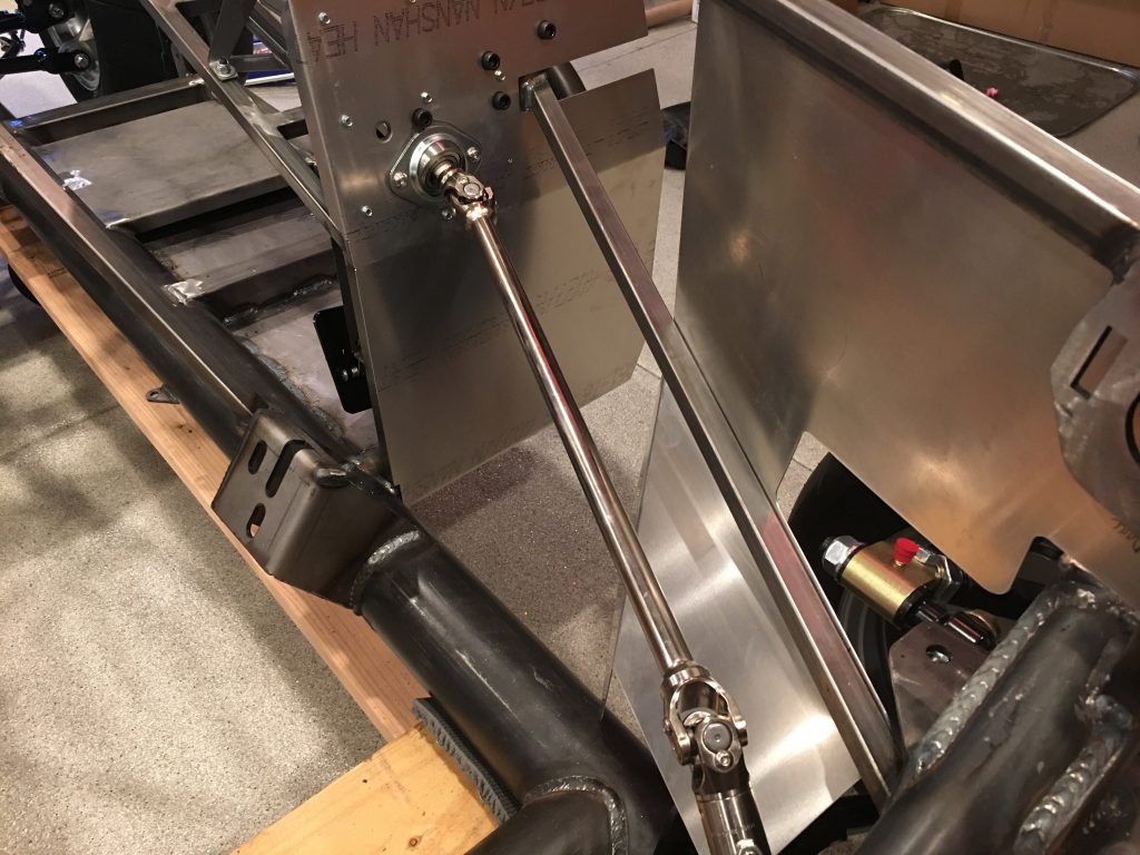
The first step in installing the electric power steering (EPS) system is to cut the steering shaft. I ended up moving the electric motor back almost as far as it could go and then taking some measurements from the engine mount to ensure I’ll have plenty of clearance.

I just started with a single cut in the shaft because this would let me adjust the motor up or down from there, but it looks like this spot will work absolutely perfectly. I really can’t go back any further because I’d hit the steering shaft u-joint and I’d interfere with the exhaust headers which exit just aft of here.

After determining everything will fit nicely, I cut the other end of the shaft and test fit everything.

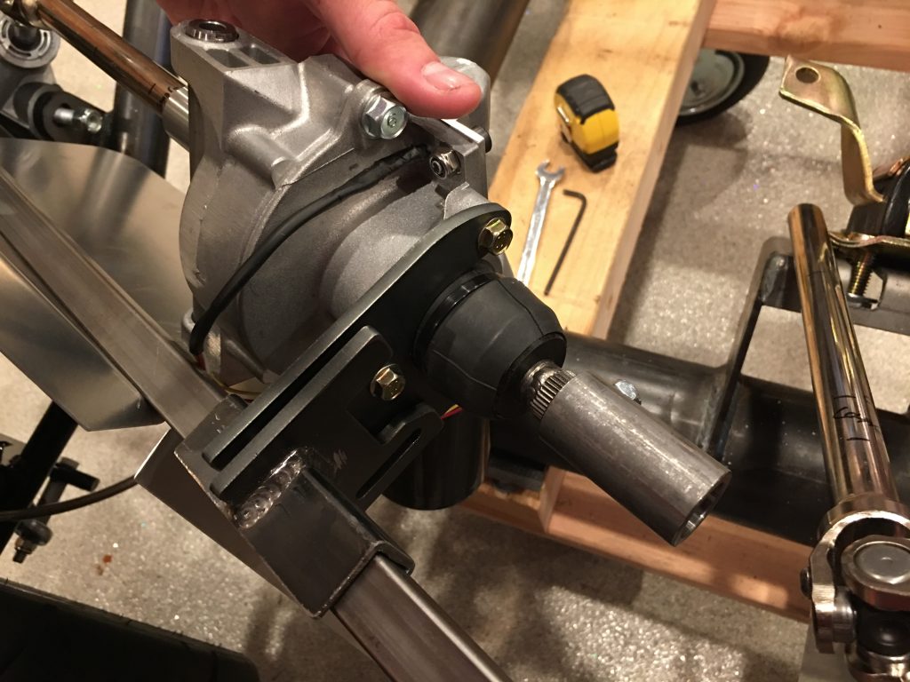
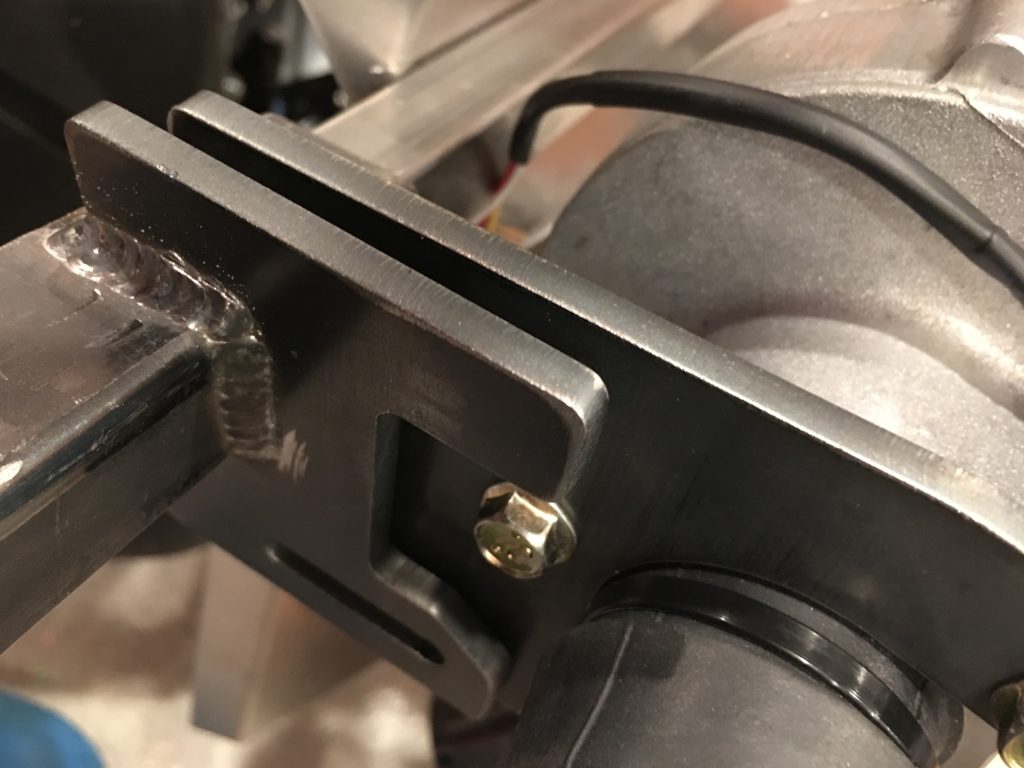
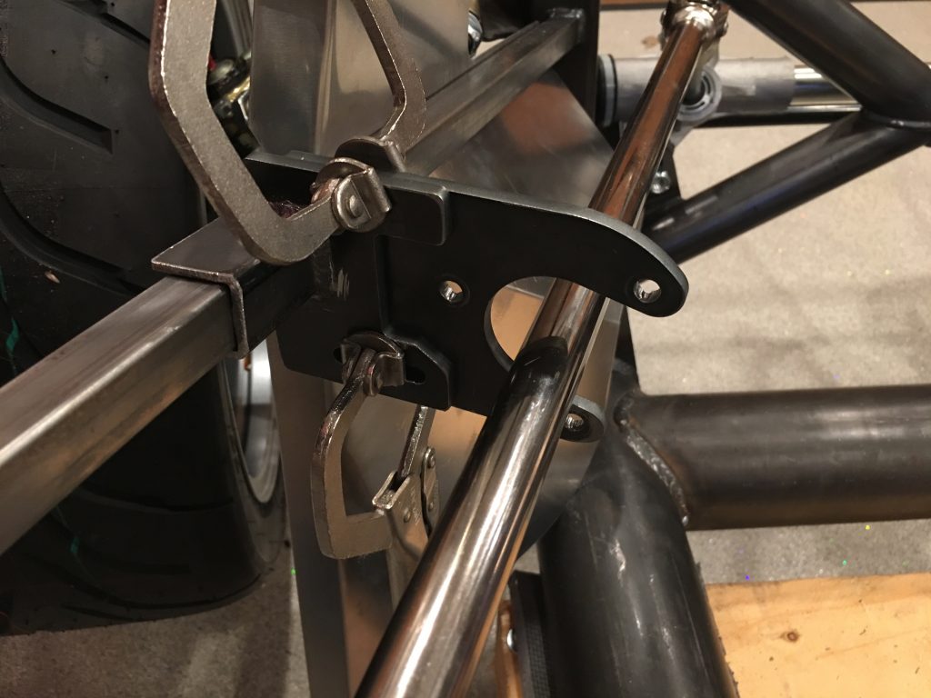
The bracket that came with the system isn’t welded at the right angle to allow the motor bracket to bolt up to it. I’ll let Erik know, but I’ll probably just cut and reweld this myself.

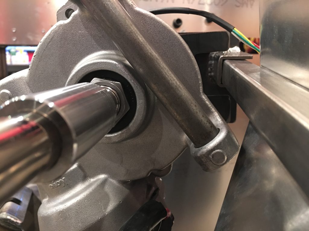
The motor clears the F panel by over 1/8″. This bracket isn’t used in this application, so I may just cut it off.

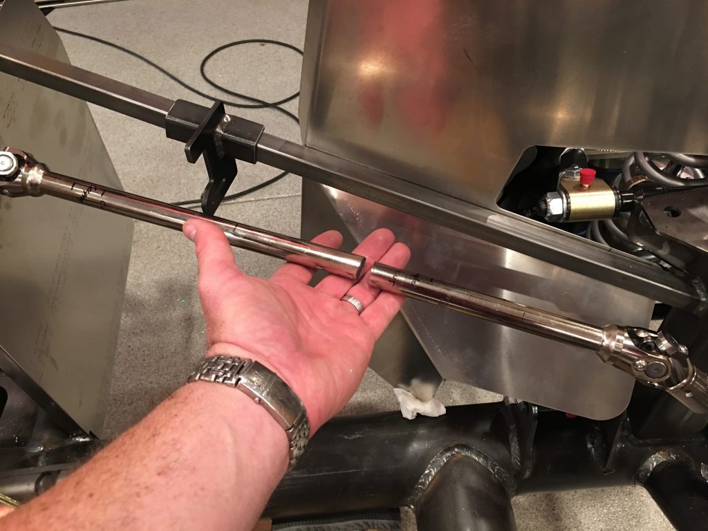
After hunting around for a good place to mount the EPS controller, I decided to mount it to the 3/4″ tubing behind the steering shaft. There’s nearly 1/4″ of clearance between the shaft and the controller, and it’s really out of the way here. The challenge is that there are only two threaded bosses on the EPS controller and they’re at an odd angle. I need to be able to access the screws later in case the controller needs to come out. Mounting it here lets me fabricate a simple bent steel bracket and easily access the mounting screws if necessary.

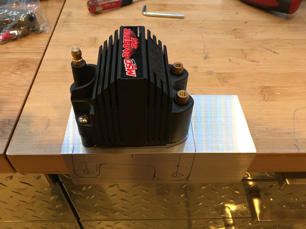
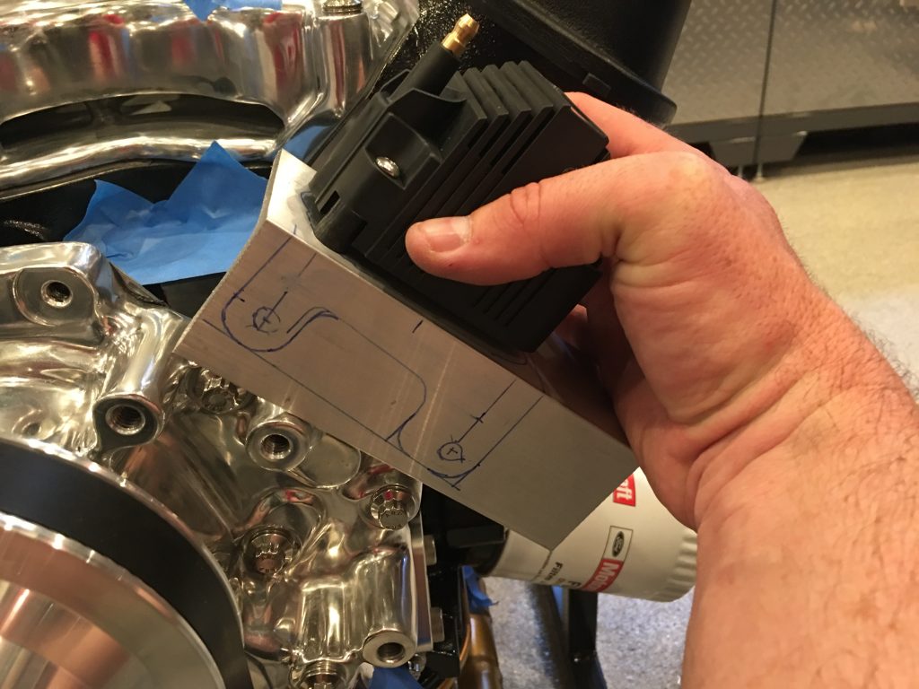
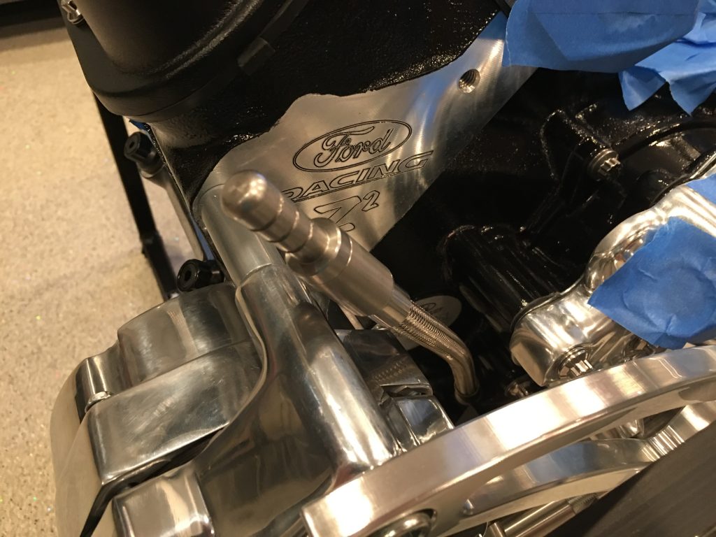
I ended up deciding to mount the ignition coil to a custom bracket that will bolt to the front of the water pump. I had a piece of scrap aluminum angle, so I took some measurements and laid out the shape of the bracket.

Once I cut out the bracket, it will bolt to the front of the water pump using these two bolts. This should clear everything around it and provide a nice, short run from the coil to the distributor.

Steering and Fuel Tank

I started installing the steering system by installing the bearing block in the firewall and slipping the steering shaft up through it.

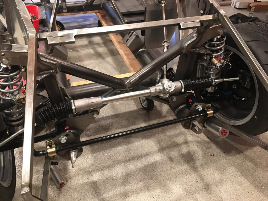
I then installed the steering rack into the front of the chassis. The brackets needed some bending to allow the mounting lugs to fit and the elongated hole on the left side (right in this picture) needed to be elongated further on the front bracket to allow the rack to slide far enough to the left to get the right bolt installed.
I installed the upper pillow block and slipped the upper steering shaft through and into the lower shaft to lock in the final position.

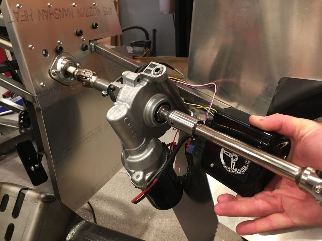
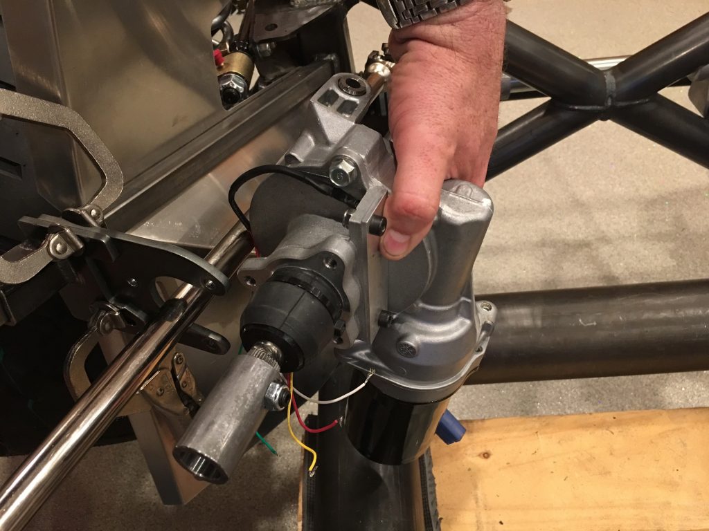
I ordered an electric power steering system from Erik Hansen on the FFR forum. After grinding and filing the bracket on the left to fit over the 3/4″ tube, I test fit it along with the bracket on the right until it’s roughly centered around the shaft. The instructions specify how far down the steering shaft it should be installed, but that puts the bracket quite a bit farther forward than this. Ordinarily, that wouldn’t be a problem, but the fat tire F panel will interfere with the bracket as well as the motor if I move it farther forward (I might even need to move it farther back from here)

Here’s the motor that will be installed inline with the steering shaft. I need to confirm that moving it back this much won’t cause any interference with the engine, but I think it will be fine.

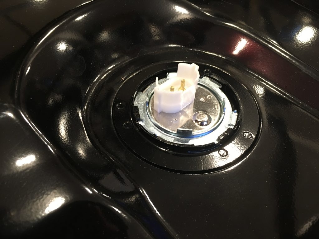
I’ve been looking for a spot to mount the remote reservoirs for our quad-adjustable shocks, but I was concerned that the fuel tank will limit accessibility. I figured the easiest way to make sure was to just install the tank. Before doing so, I installed the fuel level sender in the center of the tank.

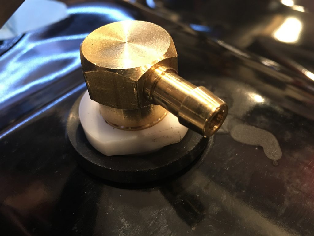
I also installed the vent at the highest point in the tank.

Finally, I installed the tank in the car.

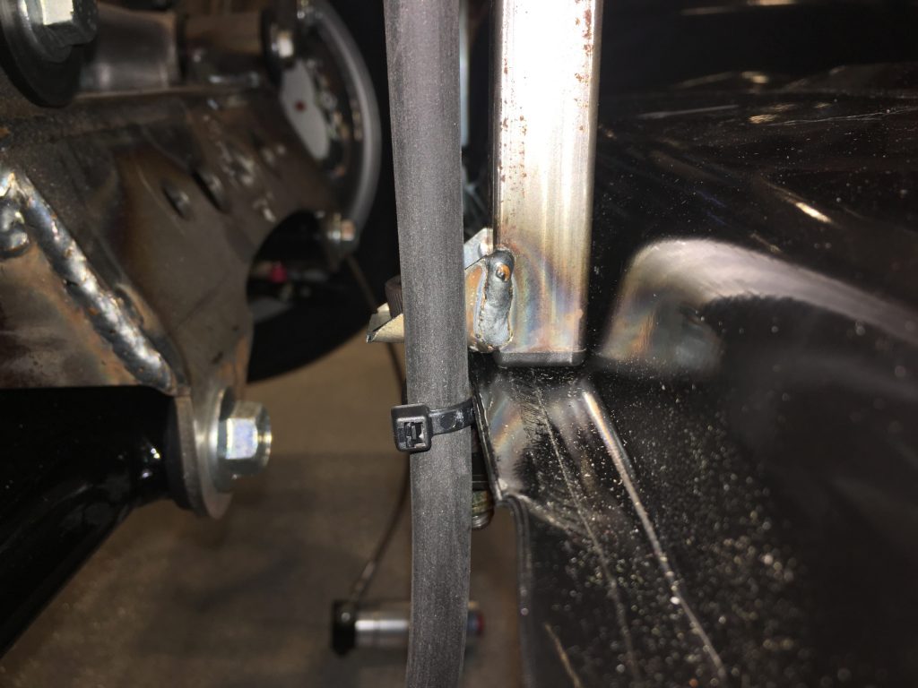
Getting the tank up high enough to start the bolts required bending the flanges down where the tank sits against the bottom of the square tubing. Finally, I zip tied the vent tubing to the 3/4″ tubing, running it up and over to the left side of the car (though I’m not sure if this will be the final routing).

Pedals and Strut Spacers

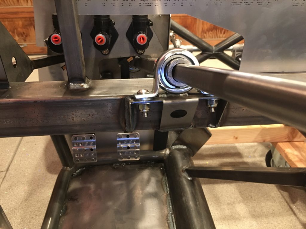
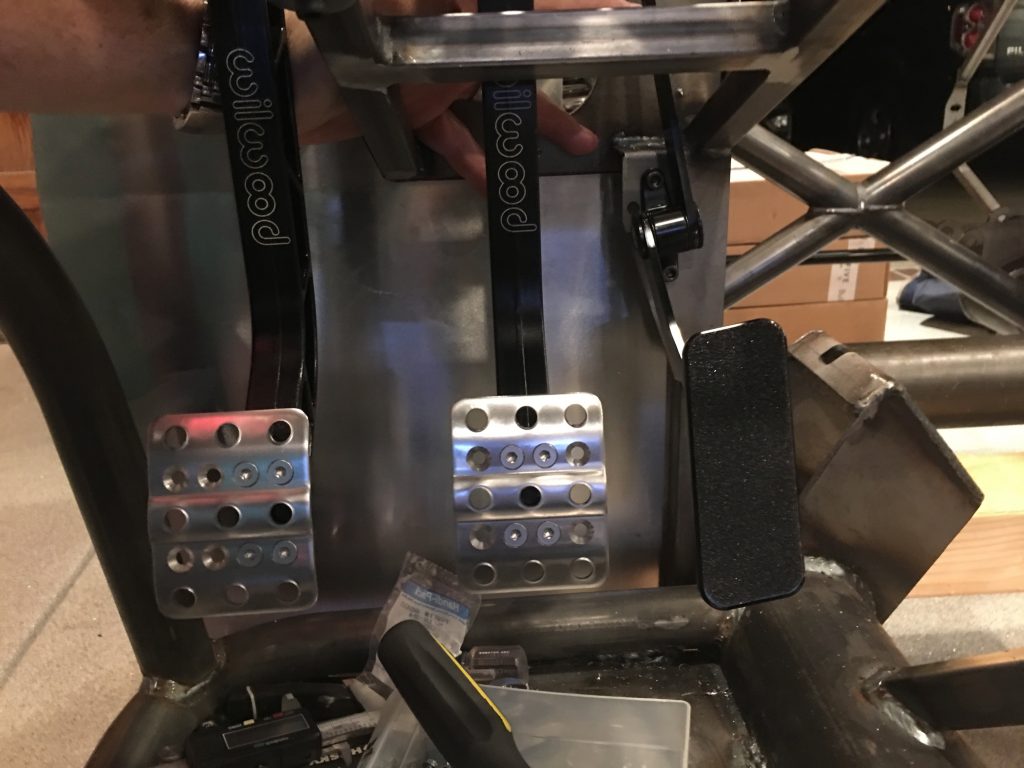
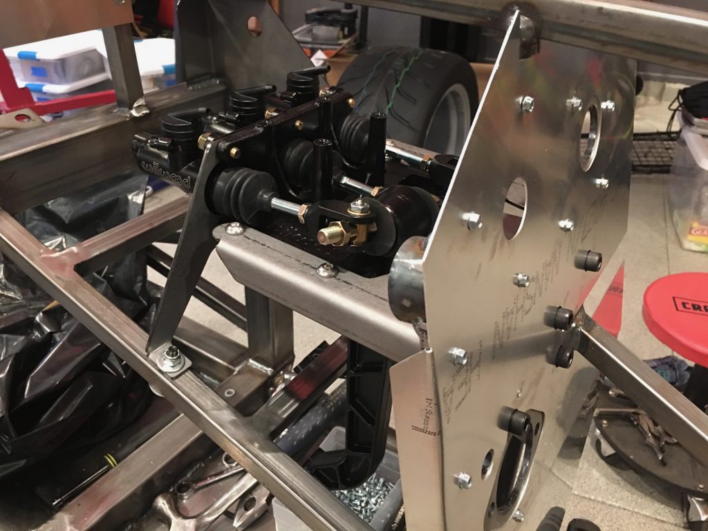
I finished adjusting the brake balance bar and adjusted the brake pedal to stop just before hitting the 3/4″ square tube at the top of the picture. Afterward, I adjusted the clutch pedal resting position to be aligned with the brake pedal. I ended up having to cut off about 1/4″ of the threaded shafts on all three master cylinders in order to position the pedals correctly.

After finishing the brake and clutch pedals, I installed the accelerator pedal to the bracket at the front of the foot box. I adjusted the brake and clutch pedal pads to get maximum width and roughly center the brake pedal.

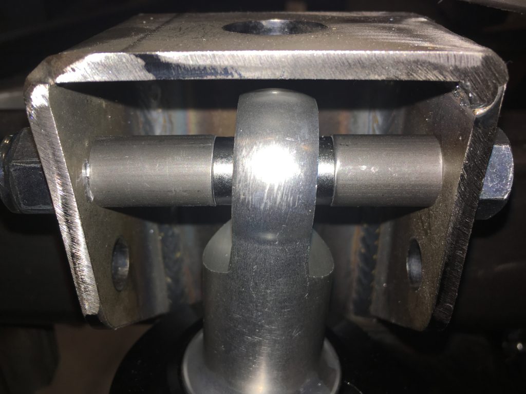
Finally, I installed all of the spacers that I machined last night. Everything fit perfectly, but most of them were pretty tight. Once the spacers and chassis are powder coated, I’m not going to be able to get them in without trimming them a little bit, but that can wait until everything comes apart.

Turned Spacers for Struts and Alternator

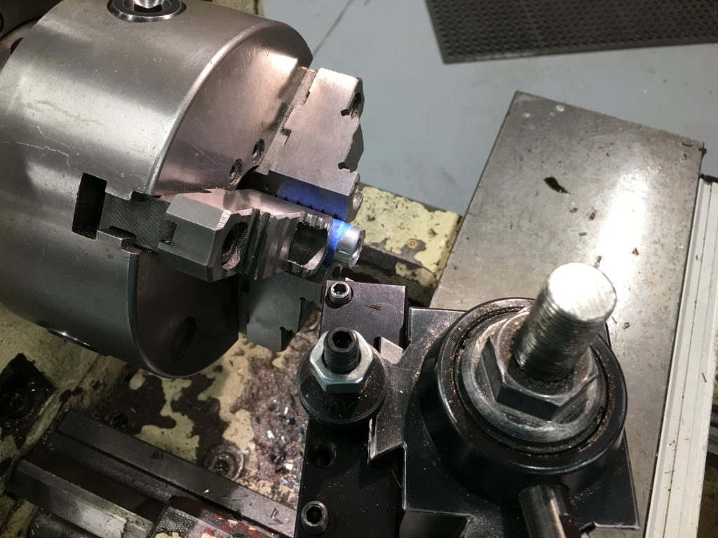
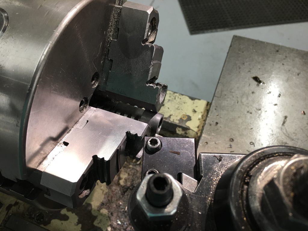
I needed to make custom length spacers for the struts and alternator mount, so I stopped by the TechShop after dinner to turn them on the lathe. I ordered a 2″ spacer from March Performance that is already powdercoated, so I wrapped it with some tape to protect the finish. I turned this down to 1.745″

I need spacers of a bunch of different lengths for the struts. I picked up some 0.509″ ID tubing with 0.058″ wall thickness from McMaster Carr and rough cut them on the chop saw about 0.100″ long. I then turned down each end to make them perfectly square and the right length.

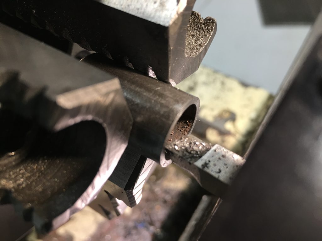
Trimming the spacers leaves a burr on the inner edge, so I repositioned the cutter and trimmed it off of each end of all of the spacers.

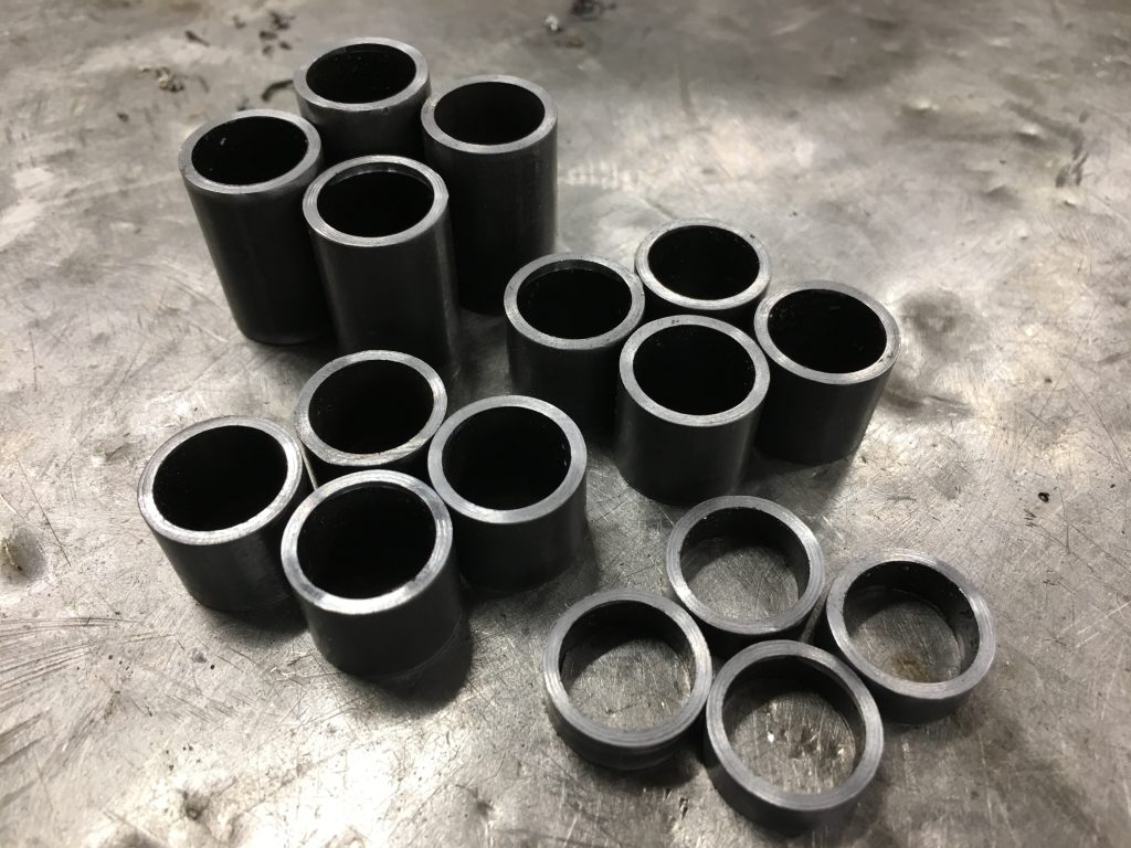
Here are the finished spacers. I’ll powdercoat these when the car comes completely apart for chassis finishing, but for now I’m going to install these bare.

Afer I got home, I installed the alternator spacer.

I installed it along with the oil dipstick tube. The bottom of the tube is installed with a little bit of black RTV to prevent oil leaks.

Installed Pedal Box

Jenn’s been sick since we got back from vacation. She’s disappointed to not be able to work on the car, but she wants to see some progress, so she’s been fine with me working on the car alone the last few days.

Next up is to install the pedal box. The complete kit comes with the Wilwood pedal box that contains the brake and clutch pedals. The brake pedal is set up to depress two master cylinders (one for the front brakes and one for the rear). The clutch pedal can use a master cylinder for those (like us) who are using a hydraulic clutch, or it can be configured to use a clutch cable for those running a manual clutch.

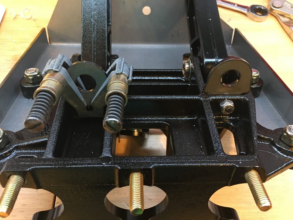
Both the clutch and brake pedals have switches installed so that systems can know when they’re depressed. The switches are mounted to tabs that need to be installed on the pedal box. To drill the holes, I clamped the tabs to the opposite side of the mounting flange since there is no room to drill from the other side. If you do this, don’t push the tab all the way down against the adjacent side flanges since they slope up toward the pedal and the hole won’t be aligned when you move the tab to the other side of the mounting flange. I just eyeballed it and it worked out great. You can see the right tab is already mounted and the left is ready to be drilled.
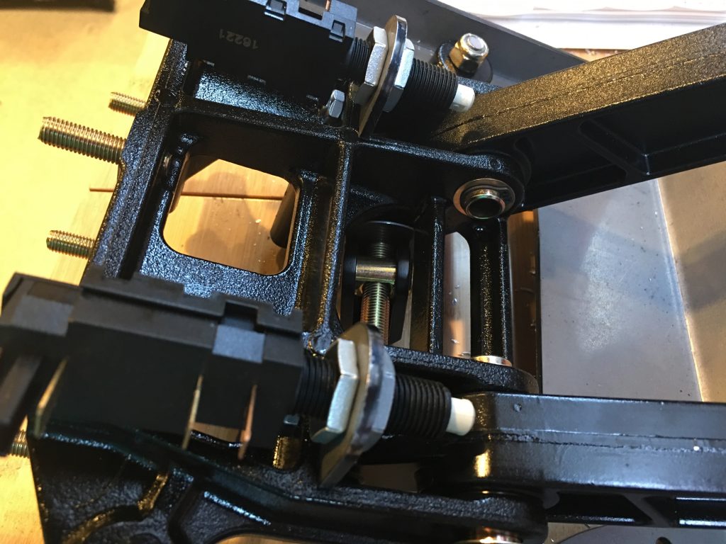
Once the tabs are in place, the switches can be installed. I’ll adjust the offset for these once all the systems are hooked up.

When I tried to install the pedal box in the car, two of the screws that I installed yesterday interfered. I removed them, installed the pedal box and then drilled through this flange. After removing the pedal box, I enlarged these holes to provide clearance for the screws (and eventually the rivet shop heads).

After fitting the rear mounting plate, I marked and drilled holes through the lower 3/4″ square tubing. Initially, they landed almost flush with the edge of the tubing. I couldn’t drill the holes there since that would compromise the side of the tubing. I ended up shifting the holes over about 1/16″. There is enough flex in all of the components that they can absorb some offset. You just need to make sure all of the bolts are installed loosely before tightening everything down.

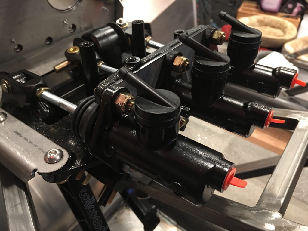
You can see that the clutch reservoir (closest in the picture) has a larger bore than the brake cylinders. After installing everything, I realized that the brake balance bar was misadjusted from the factory. I ended up removing one of the brake cylinders so that I could adjust the side-to-side clearance of the balance bar. After adjusting the balance bar, I threaded in the master cylinder shafts until the cylinders open all the way up when the pedals are released.