Steering Linkage, Chassis Mods and Timing Pointer

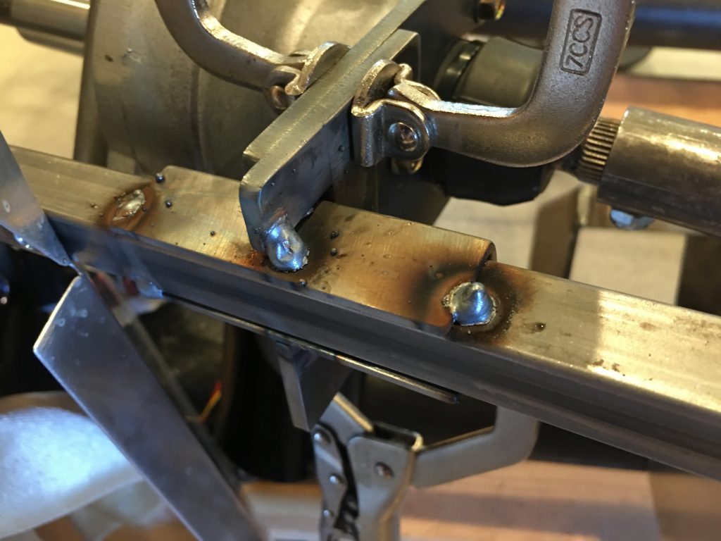
I installed the EPS brackets and tacked the two pieces of the bracket together and tacked it to the chassis. I’ll finish welding this after pulling the steering linkage off and unscrewing the aluminum F panel.

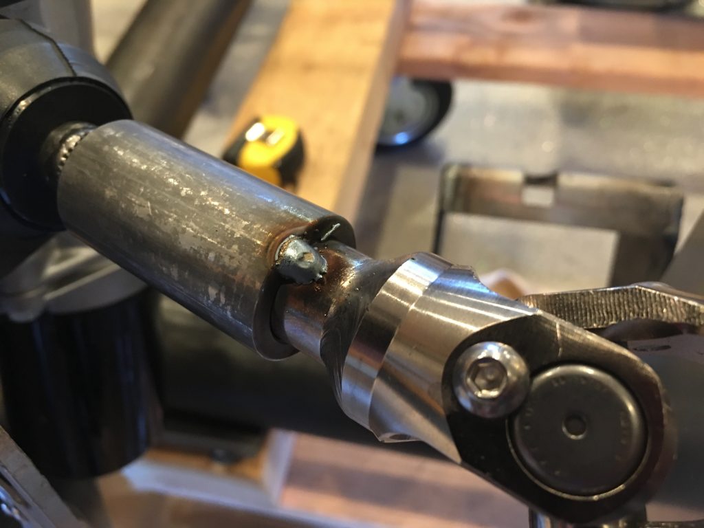
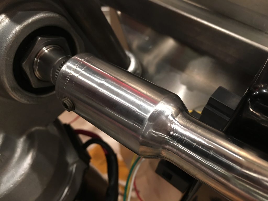
With the steering linking all bolted into its final location, I tacked the upper coupler to the steering shaft.

I also tacked the lower coupler.

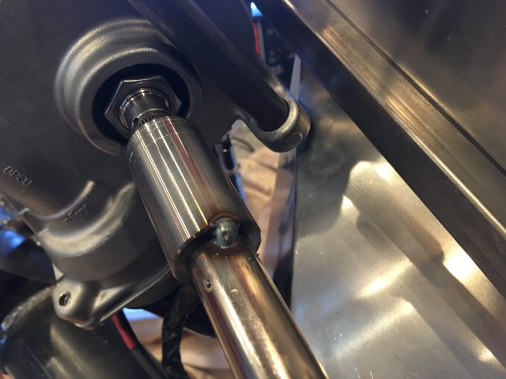
I then TIG welded the couplers all the way around and ground everything smooth. Here’s the upper coupler.

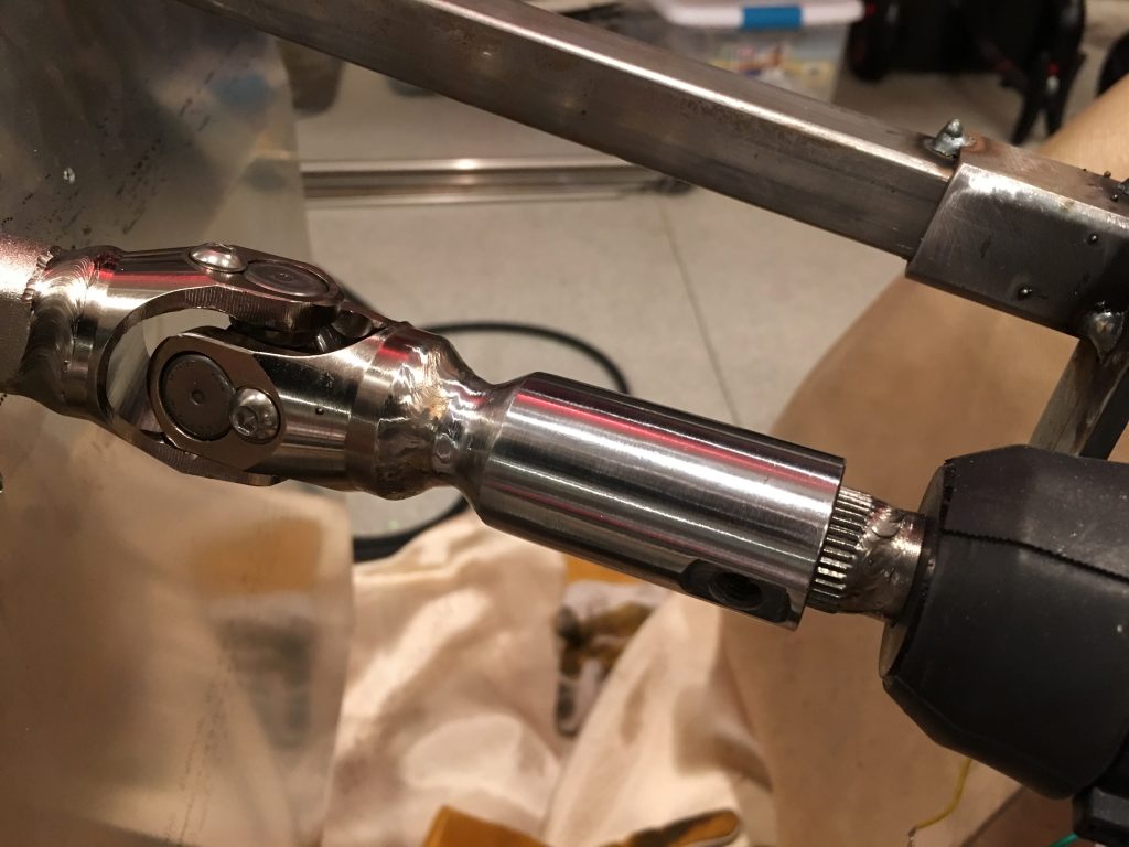
And here’s the lower coupler. I may have these chromed after the chassis comes apart for finishing.

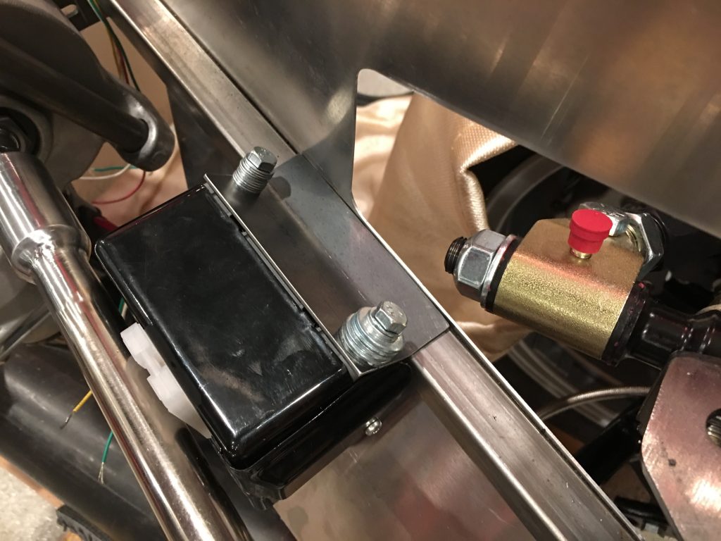
While I was at the TechShop, I fabbed up a piece of 16ga steel to attach the EPS controller to the chassis. The bolts are metric, so the only ones I had on hand were too long. I’ll pick up the right bolts before bolting this in for good.

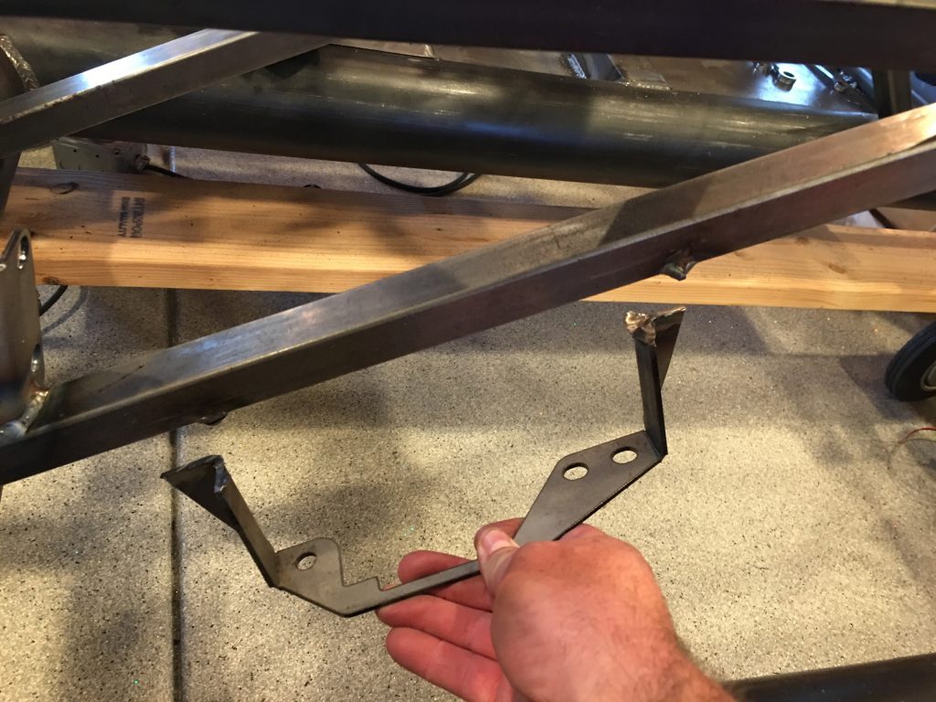
Since I’m relocating the parking brake, I cut off the bracket that holds the handle. I’ll have to fab up a bracket once I figure out the new location.

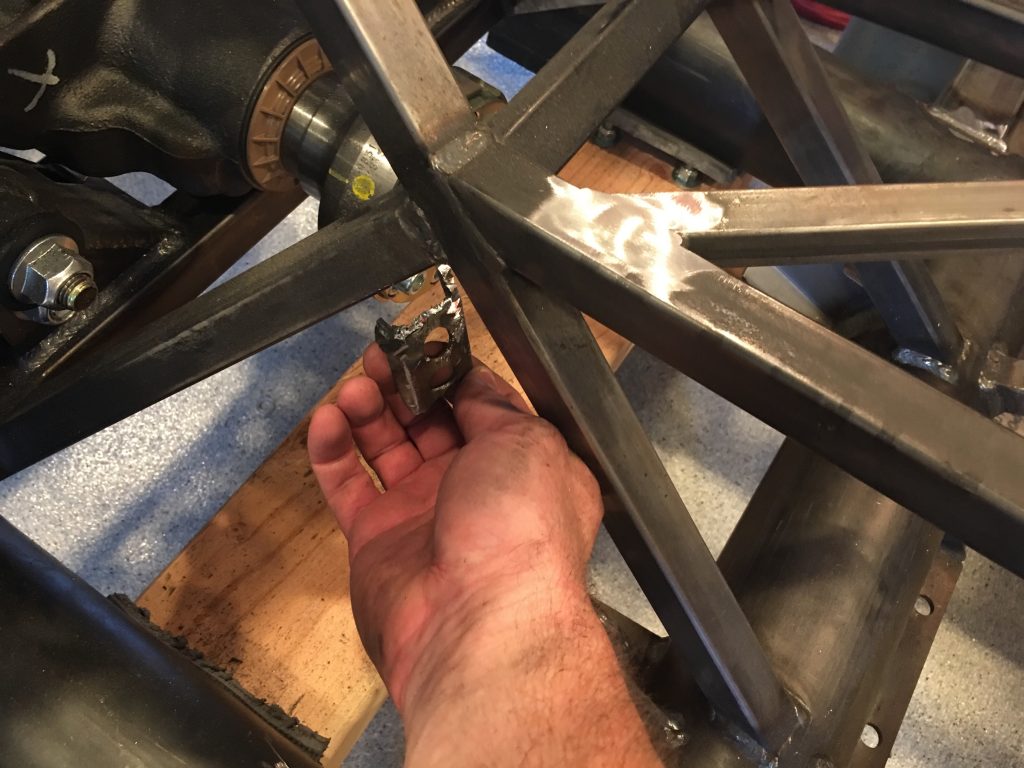
I also cut off the bracket that hold the parking brake cables. I really wish I had cut this off before installing the differential; it was a real challenge cutting this off while working around it.

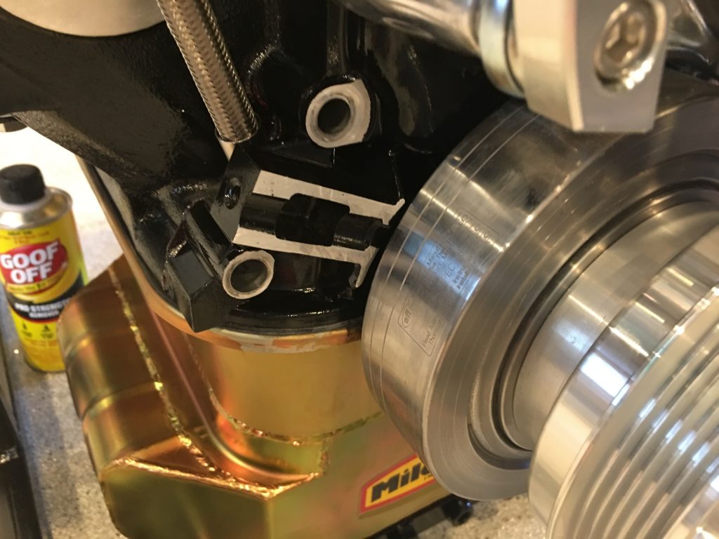
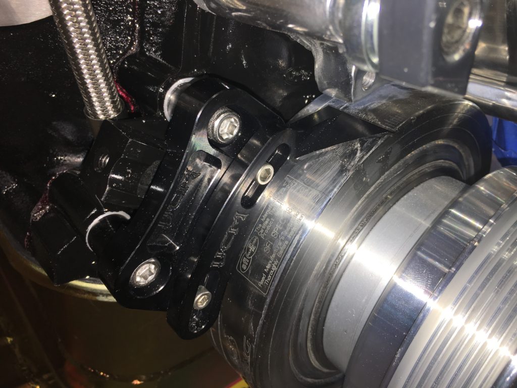
I originally purchased a timing pointer that mounts at the 2 o’clock position, but it turns out that that would be pretty hard to see since we’re using a water pump with a driver side inlet. I replaced that with one that mounts at the 11 o’clock position, but it interferes with a bracket on the Ford timing cover. Ford confirmed that it’s unnecessary, so I cut it off with a cutoff wheel.

After touching up the paint, I installed the pointer and aligned it with the 0º mark.

Installed Pedal Box

Jenn’s been sick since we got back from vacation. She’s disappointed to not be able to work on the car, but she wants to see some progress, so she’s been fine with me working on the car alone the last few days.

Next up is to install the pedal box. The complete kit comes with the Wilwood pedal box that contains the brake and clutch pedals. The brake pedal is set up to depress two master cylinders (one for the front brakes and one for the rear). The clutch pedal can use a master cylinder for those (like us) who are using a hydraulic clutch, or it can be configured to use a clutch cable for those running a manual clutch.

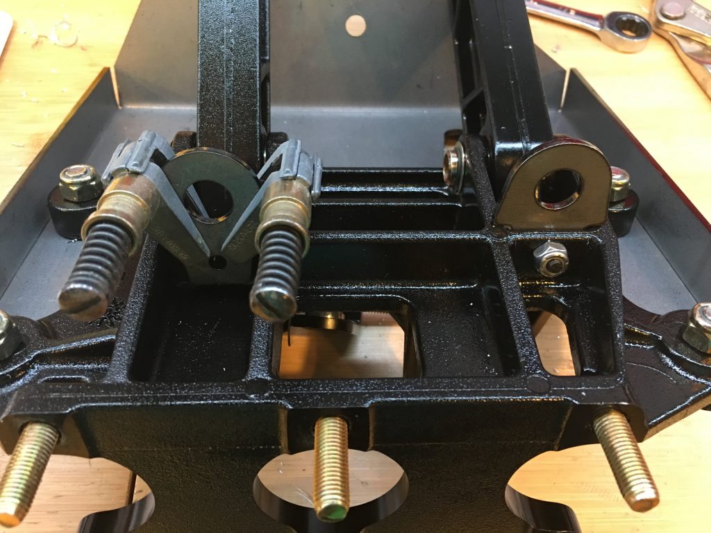
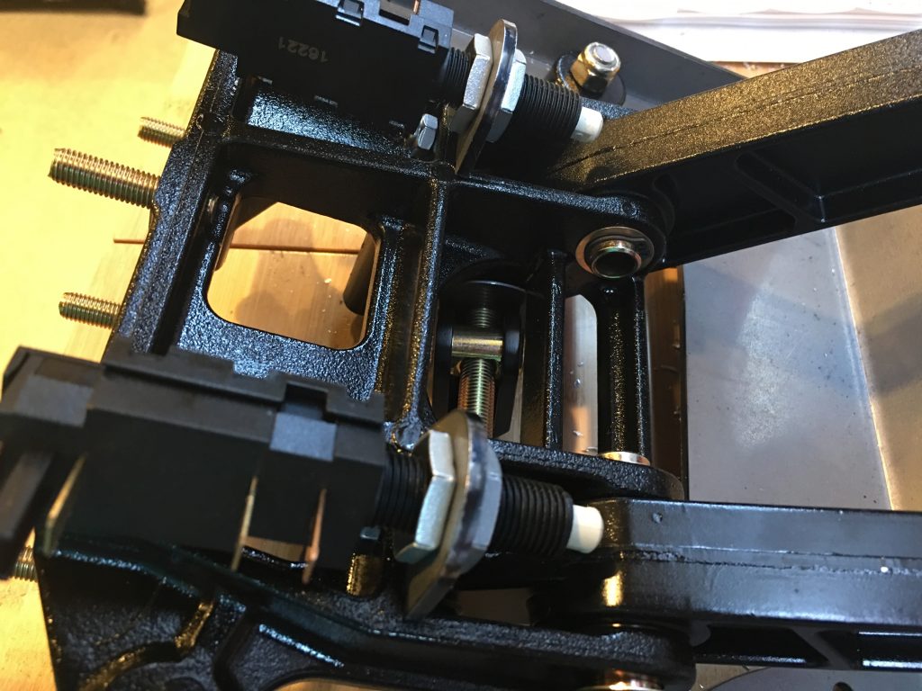
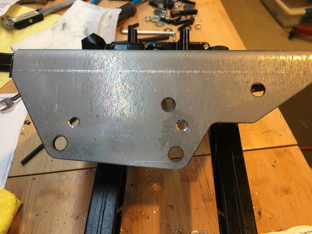
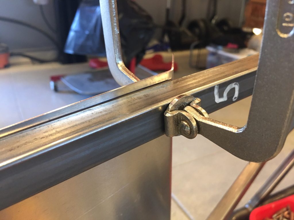
Both the clutch and brake pedals have switches installed so that systems can know when they’re depressed. The switches are mounted to tabs that need to be installed on the pedal box. To drill the holes, I clamped the tabs to the opposite side of the mounting flange since there is no room to drill from the other side. If you do this, don’t push the tab all the way down against the adjacent side flanges since they slope up toward the pedal and the hole won’t be aligned when you move the tab to the other side of the mounting flange. I just eyeballed it and it worked out great. You can see the right tab is already mounted and the left is ready to be drilled.

Once the tabs are in place, the switches can be installed. I’ll adjust the offset for these once all the systems are hooked up.

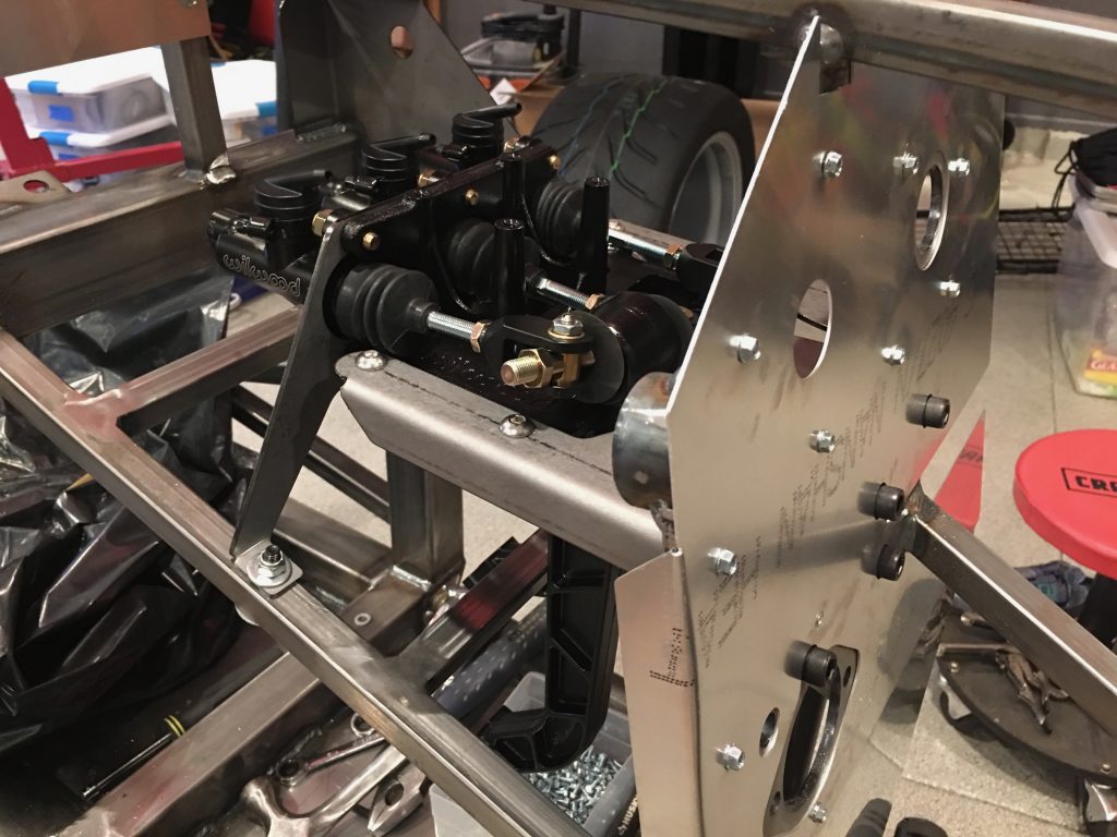
When I tried to install the pedal box in the car, two of the screws that I installed yesterday interfered. I removed them, installed the pedal box and then drilled through this flange. After removing the pedal box, I enlarged these holes to provide clearance for the screws (and eventually the rivet shop heads).

After fitting the rear mounting plate, I marked and drilled holes through the lower 3/4″ square tubing. Initially, they landed almost flush with the edge of the tubing. I couldn’t drill the holes there since that would compromise the side of the tubing. I ended up shifting the holes over about 1/16″. There is enough flex in all of the components that they can absorb some offset. You just need to make sure all of the bolts are installed loosely before tightening everything down.

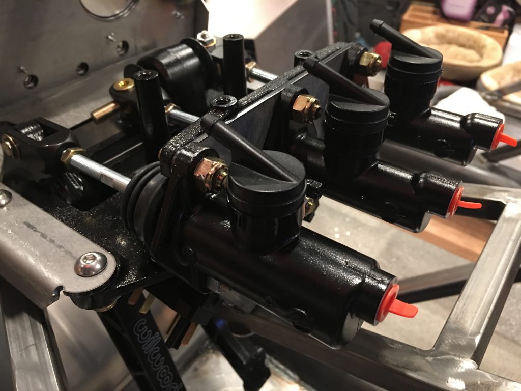
You can see that the clutch reservoir (closest in the picture) has a larger bore than the brake cylinders. After installing everything, I realized that the brake balance bar was misadjusted from the factory. I ended up removing one of the brake cylinders so that I could adjust the side-to-side clearance of the balance bar. After adjusting the balance bar, I threaded in the master cylinder shafts until the cylinders open all the way up when the pedals are released.

Parking Brake and Aluminum Panels

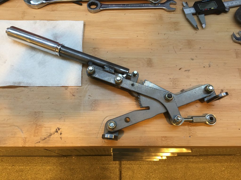
We’re relocating the parking brake to the top of the tunnel, so I wanted to assemble the mechanism so we could begin determining the best location. We can’t make a final determination until the transmission and seats are in place though.

Since we deleted the brakes from the kit order, we didn’t get the parking brake cables. Since we’re moving the parking brake anyway, the stock kit from FFR probably wouldn’t work without modification. Fortunately, Wilwood sells a universal kit (330-9371) that can be trimmed to exactly fit each application.

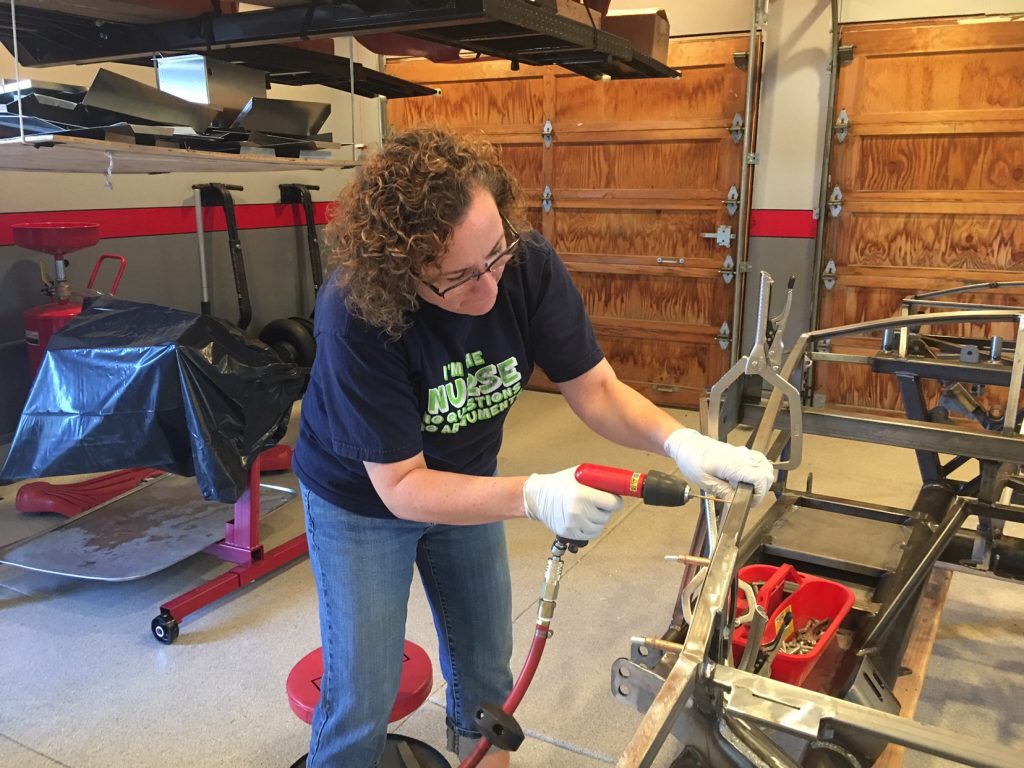
I fit and drilled the firewall to the chassis. I ran out of sheet metal screws and need to pick up some more.

I also drilled the foot box front panel to the chassis. I ended up laying out a couple of holes under the 3/4″ square tubing and needed to use a right angle drill to drill them.

Started Work on Suspension

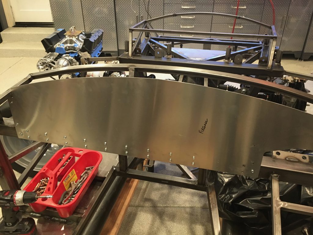
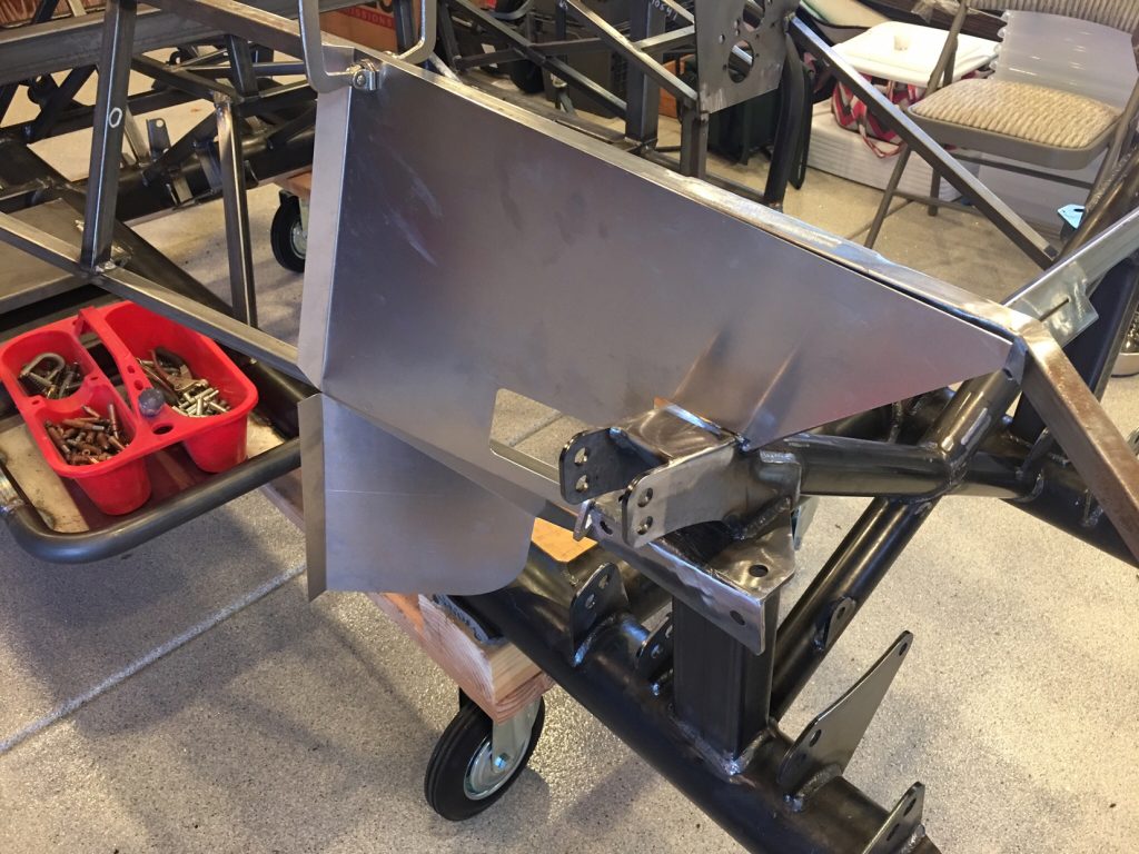
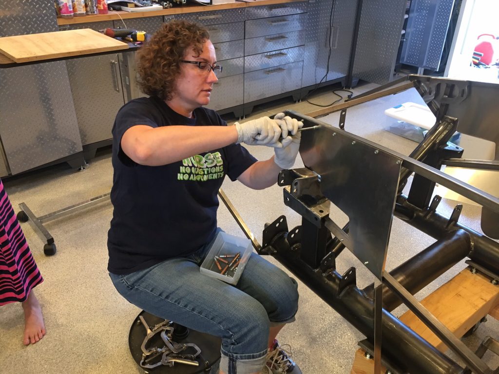
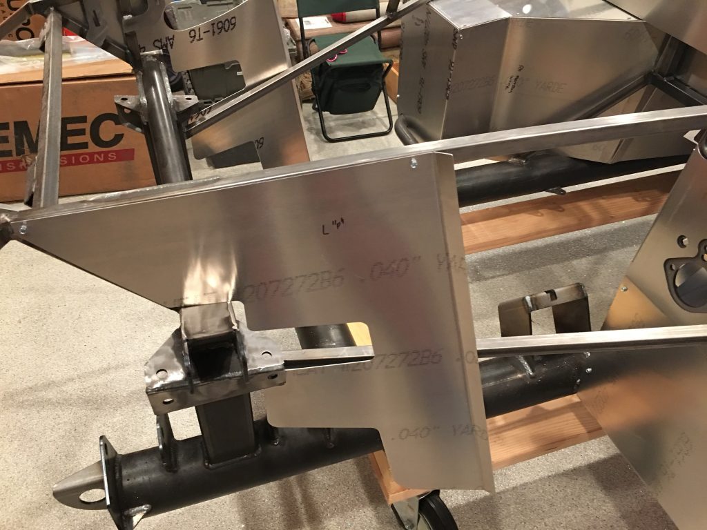
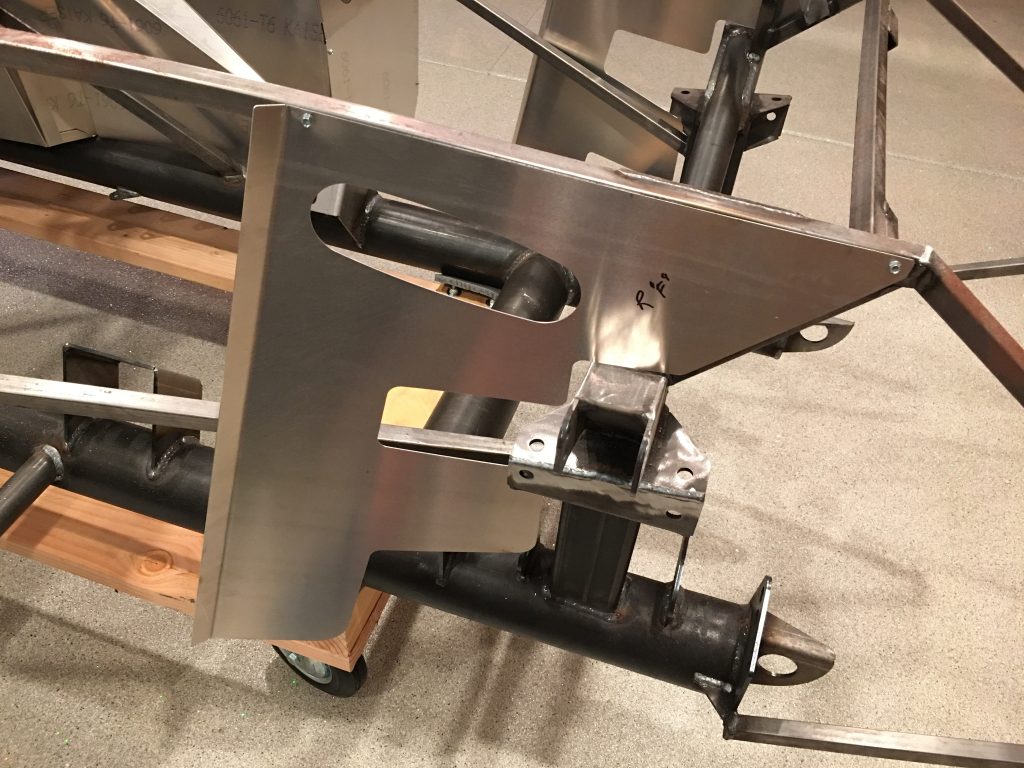
Jenn and I started work on the suspension this morning. First up is to mount the F panels. These are the Fat Tire F Panels from ffmetal.com. They let you run wider front tires (up to 275 or so) without rubbing when the wheel is turned to the stop. These are basically slid up until the lower bend is at the corner of the lower steel tube and the slid forward until the forward upper end is at the apex of the bend, then clamped in place.

That positions the panel a little bit above the upper support, so we marked and trimmed it to fit.

After laying out the holes on the F panel using a rivet fan, Jenn match drilled it to the chassis.

Since we’re going to be completely disassembling the chassis for finishing, we’re going to hold all aluminum panels on with screws until then.

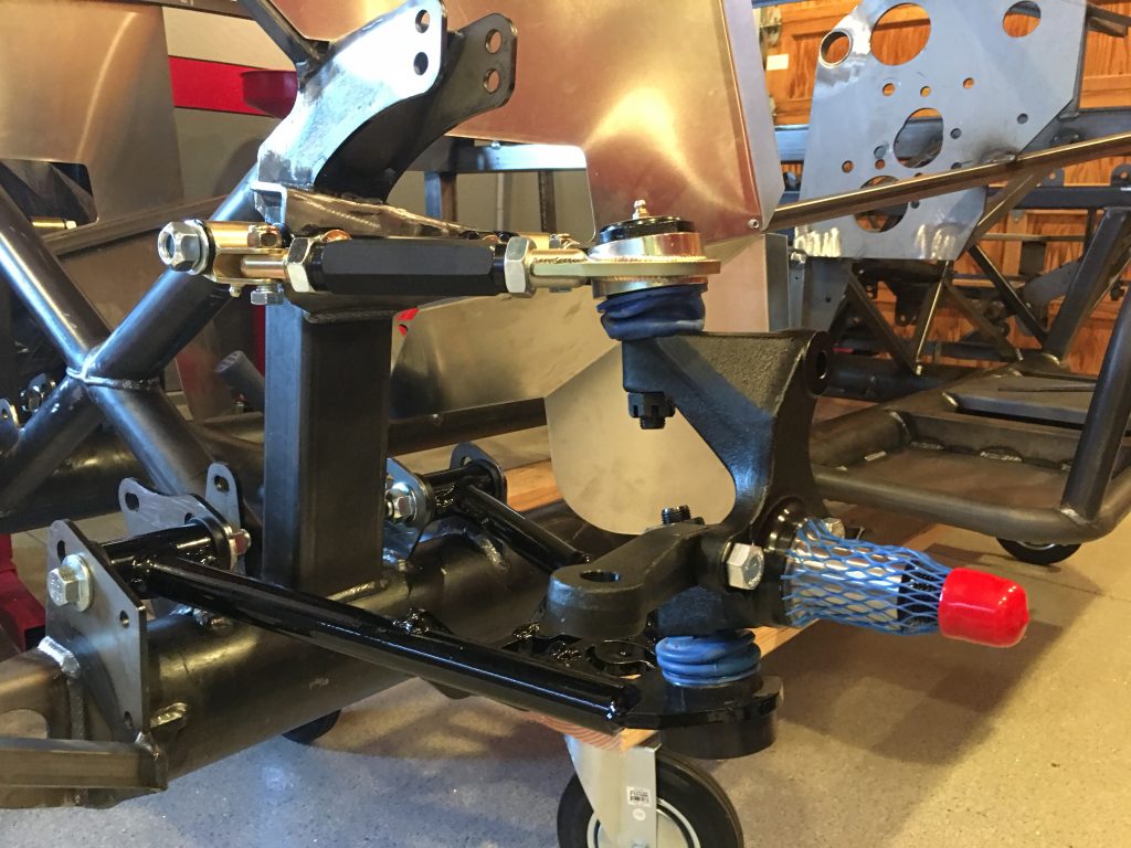
Afterward, we bolted the upper and lower control arms in place and then attached the spindles.

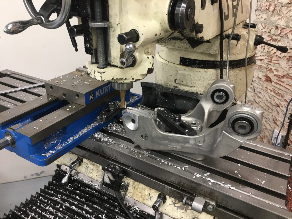
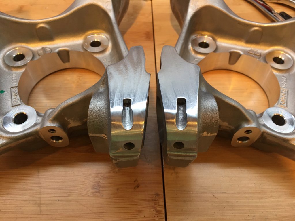
Jenn had a dinner planned with her friends, so I used that opportunity to run down to the TechShop and modify the rear knuckles. After roughly cutting off the extra ears on the band saw, I mounted them to the bed of one of the milling machines and used an end mill to clean up the cut.

Finally, I used their large disc sander to radius the corner and the scotchbrite wheel to smooth everything out.

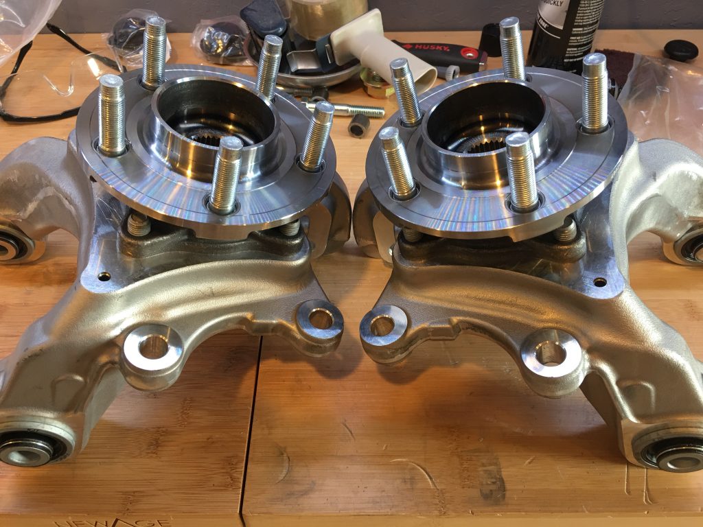
I then mounted the hubs to the knuckles. These are ready to mount on the car.

Finished Welding Floorboards

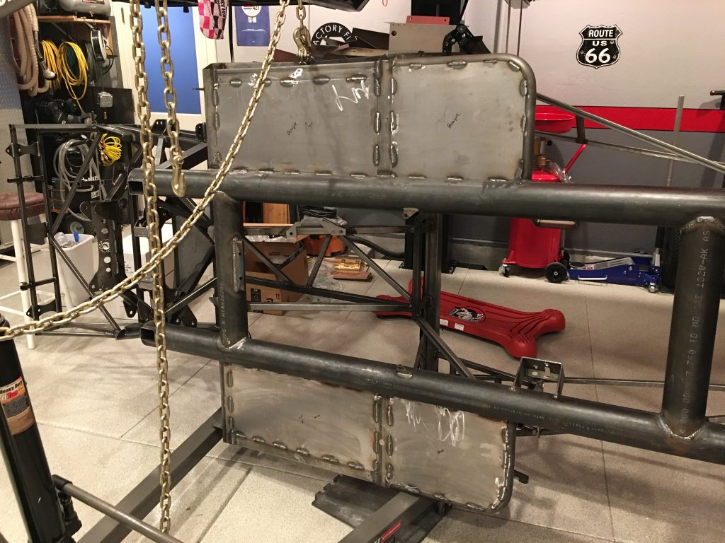
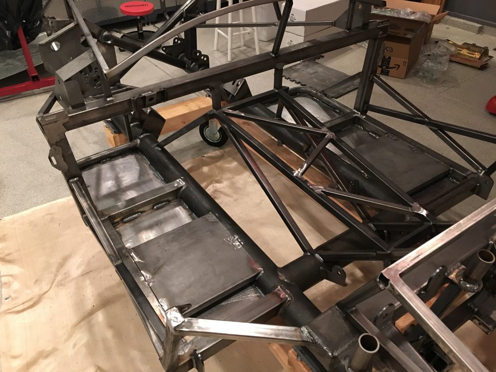
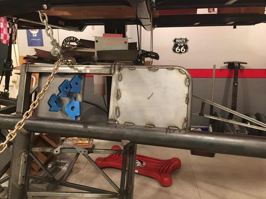
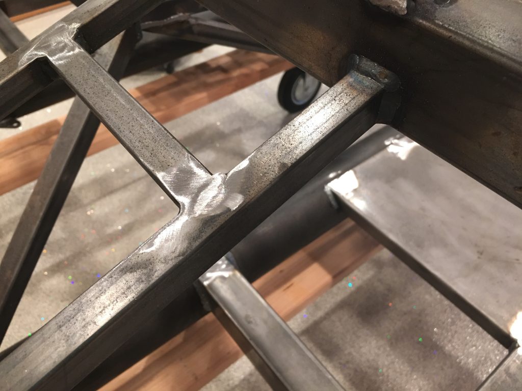
I finished grinding all of the sharp edges and weld spatter off the bottom of the chassis and then welded in the floorboards from the bottom.

I put the chassis back on the dolly and then added additional welds on top of the floorboards.

After dialing in the settings on the welder, I’m getting much more consistent welds. It’s still a little tricky to get sufficient penetration on the thick tubing without blowing through the thin plate, but using a zig-zag pattern and spending 60-70% of the weld time on the thicker stock works pretty well to get even penetration on both pieces.

Fabricated Floorboards

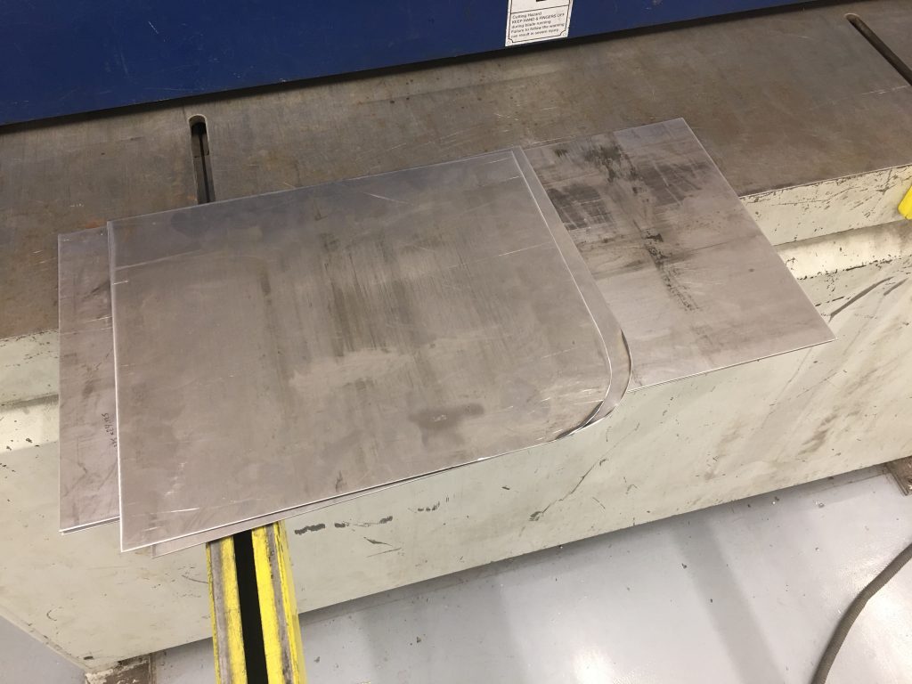
I picked up a sheet of 18ga steel at a local metal supplier this morning and stopped by the TechShop after work to cut them to size. I ended up deciding to cut each side into two pieces instead of one. Each side has a long, rectangular piece and a short, rectangular piece with a radiused corner.

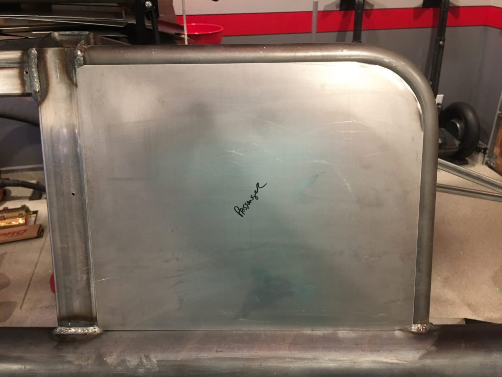
I test fit each of the panels.

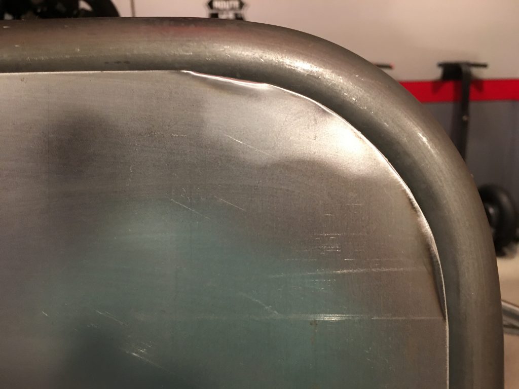
The corner radius was not quite right, but it will work just fine.

The only modifications I needed to do were to clip the corners to clear the existing welds.

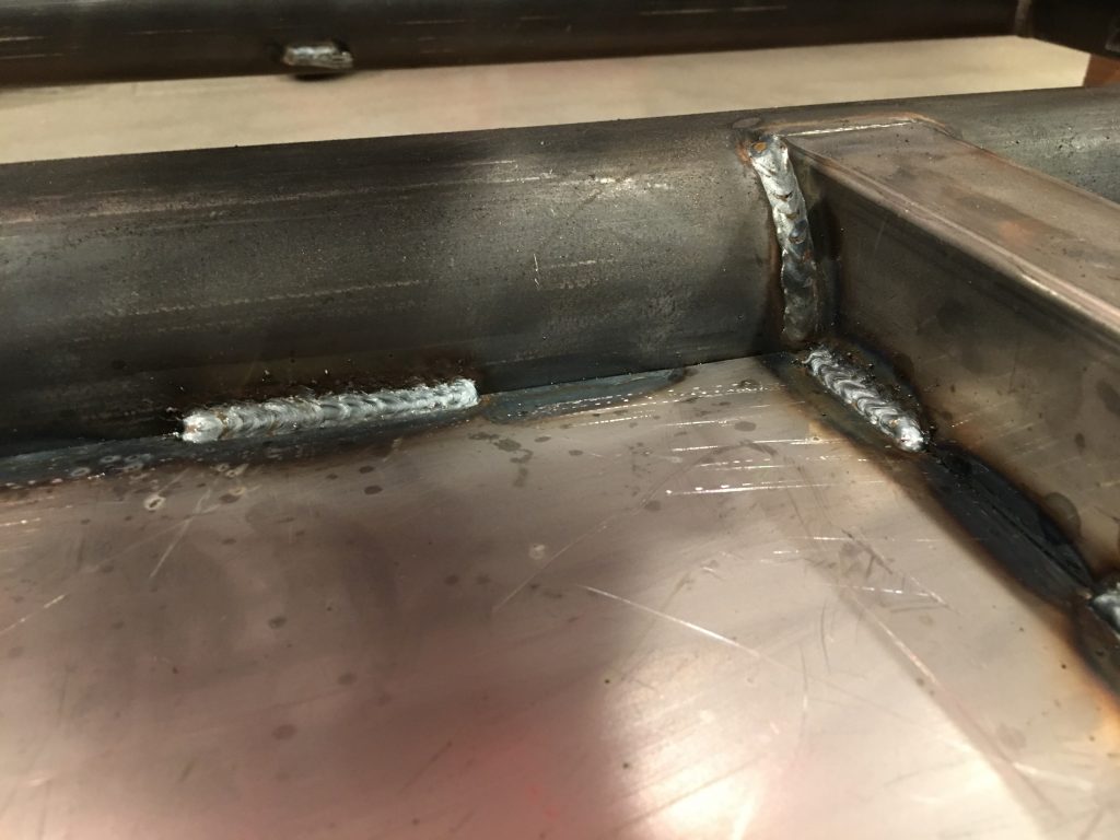
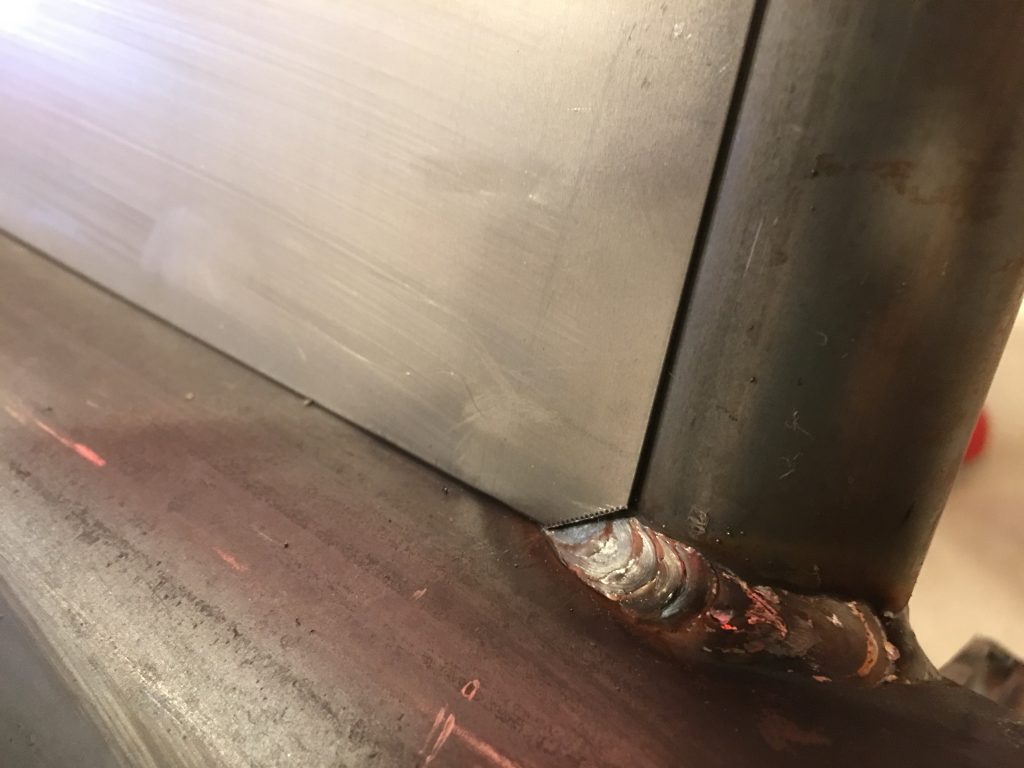
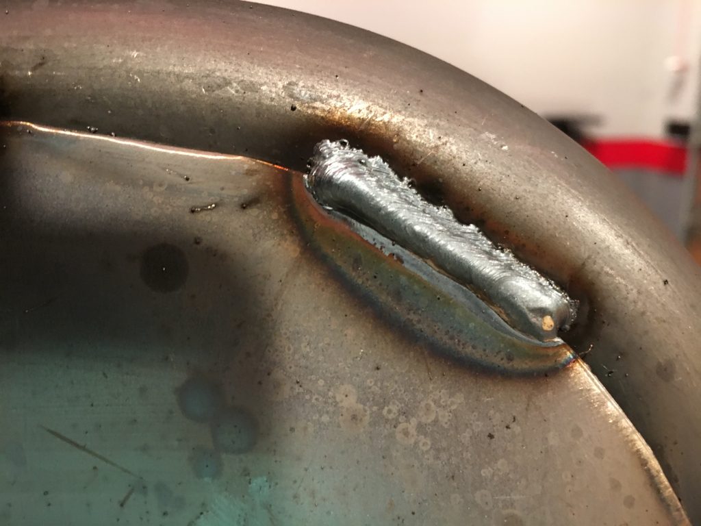
I set up the welder with the solid core wire and CO2/Argon gas bottle and welded the panel in place. I played around with different voltages/wire feed speeds until I found settings that worked pretty well.

Not all of the welds looked this good, but they should all be plenty strong. It was too late to weld in the other floorboards, so that will have to wait until tomorrow.

Painted Engine and Prepped Chassis

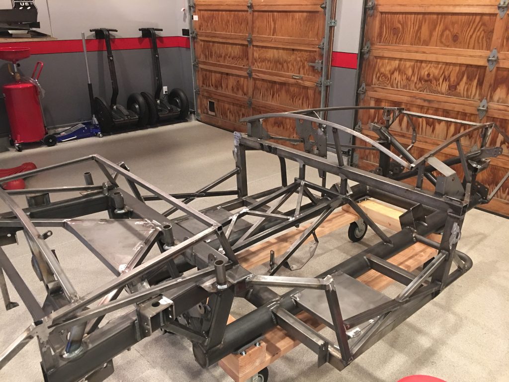
I still need to do a little more grinding on the bottom of the chassis to clean up some of the weld splatter and sharp edges. I’m also planning on welding steel floorboards onto the bottom of the chassis to better protect from road debris. I wanted to get a better look at the bottom to see if I needed one or two pieces of steel. The bottom of the round tube is essentially flush with the bottom of the square tubes, so it looks like I can use a single piece.

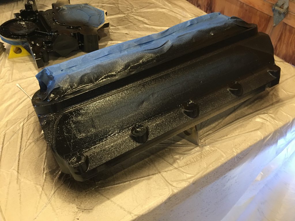
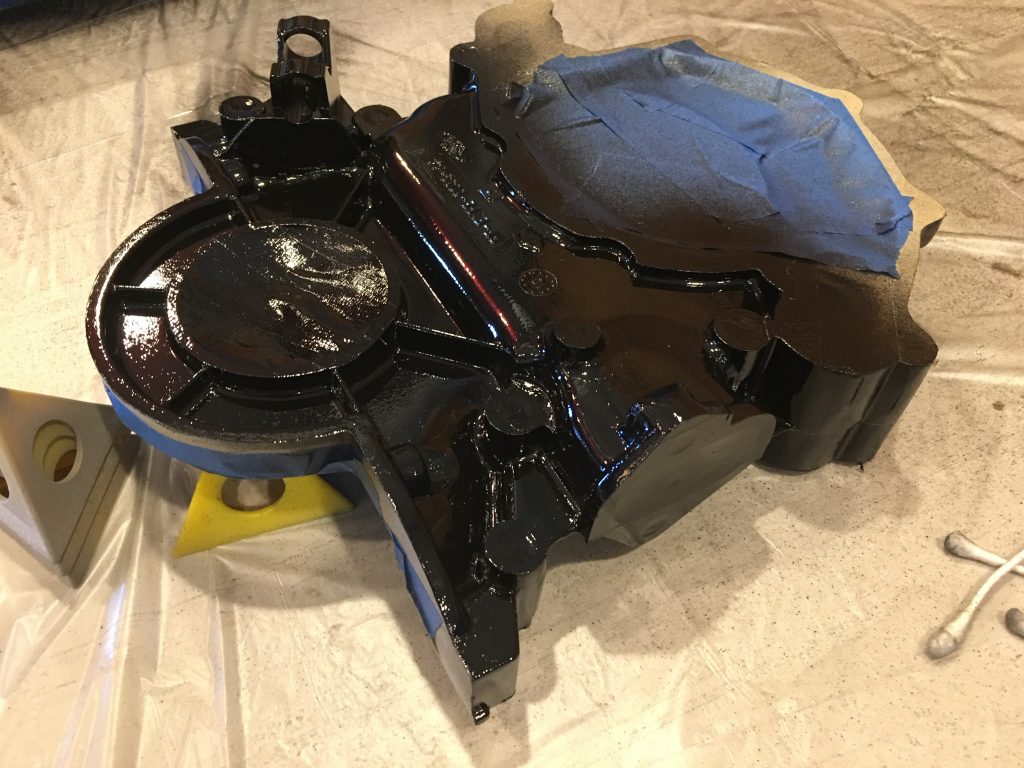
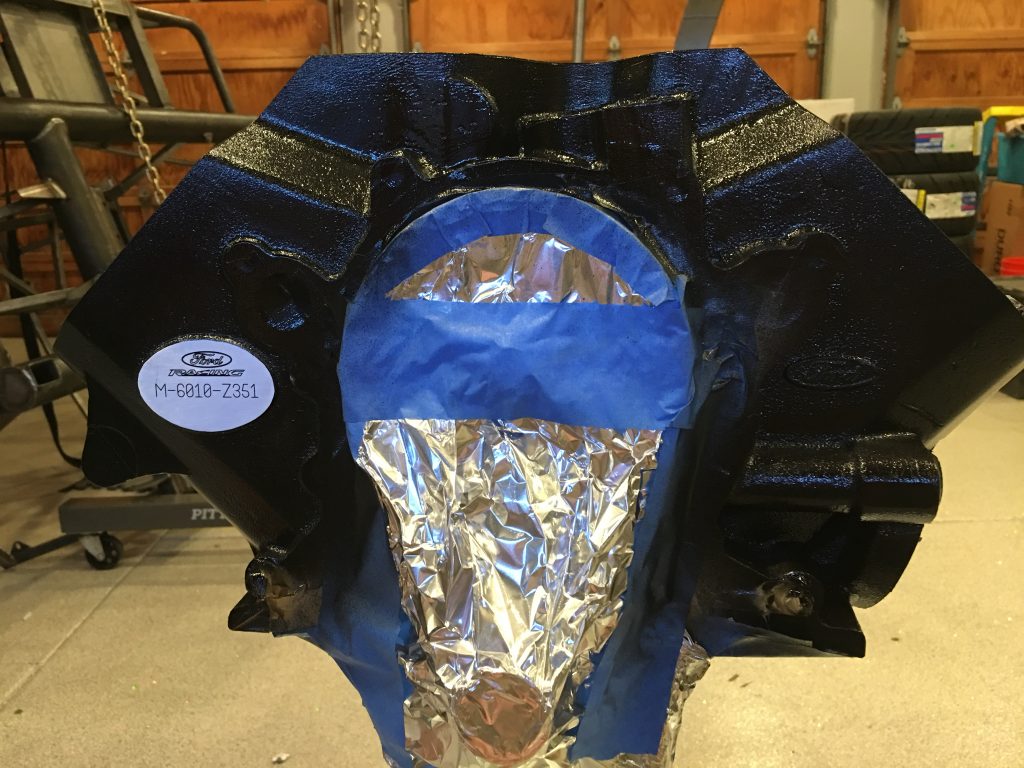
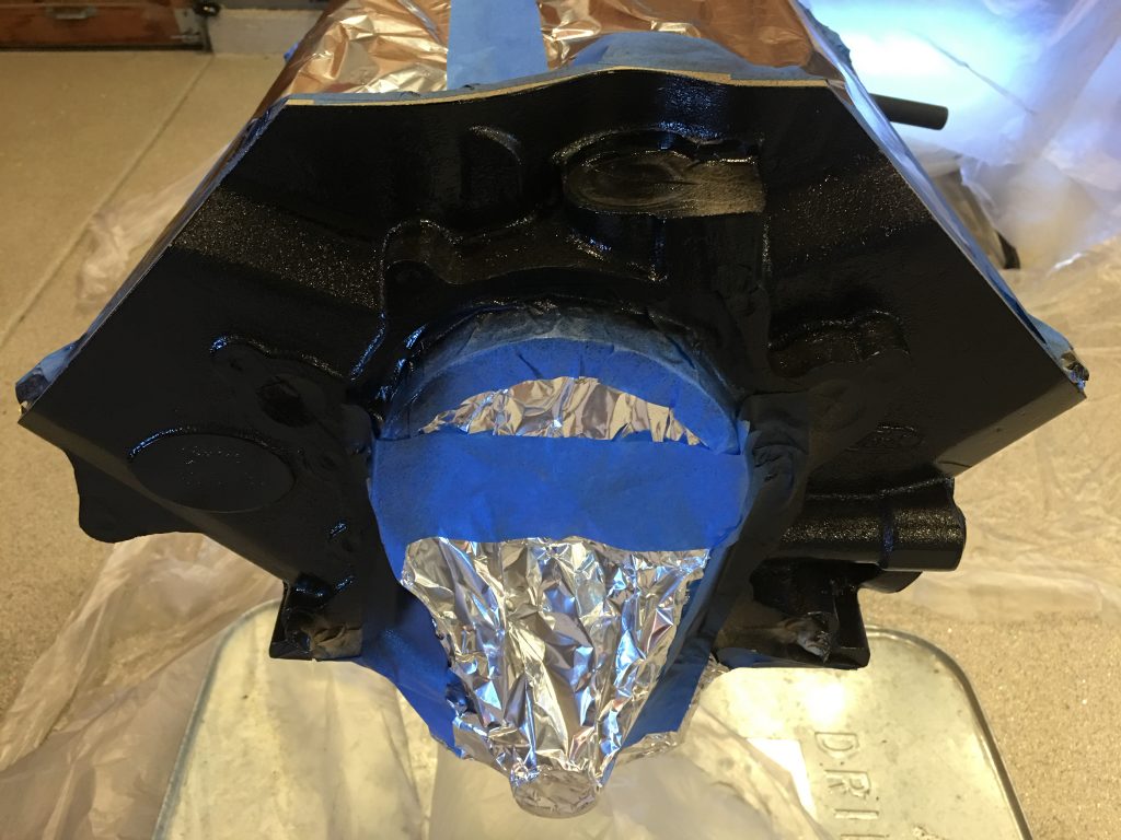
I finished taping up the engine block, heads and timing chain cover and cleaned them thoroughly before painting them with three coats of Eastwood’s high-temperature ceramic engine paint in gloss black. I haven’t pulled the tape yet since I want the paint to be fully cured before touching it. Touching the overspray on the tape showed that it will be easy to leave fingerprints in the paint until it’s cured.

All of the surfaces on the heads and blocks that were painted were a fairly rough case surface, so it doesn’t result in a truly glossy surface, but I think it looks really nice.

The timing chain cover is a smooth casting, so it looks much more glossy.

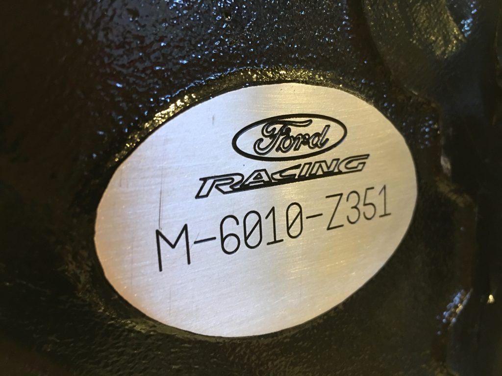
While I taped up most of the front of the engine, there was a small oval part of the casting that had been sanded smooth and engraved with the Ford Racing logo and block part number. I didn’t mask that off and painted right over it. I took some 320 and 400 grit sand paper and sanded off the paint on this oval.

This left the paint down in the engraved areas. It’s unfortunate that the “c” in Racing” wasn’t engraved properly, but I still really like the way this looks.

Chassis and IRS Knuckle Prep

I spent some time cleaning up the chassis. Although the workmanship is outstanding, there were a few things I wanted to address:

  • There were a number of sharp corners and edges that I wanted to smooth over so we don’t scrape ourselves working on the car.
  • All of the laser cut brackets had some sharp burrs from the cutting process that I wanted to clean up.
  • There was some weld splatter all over it that I wanted to clean off.
  • There were a number of places where they had ground down part of the weld, but I wanted to make them flush so that the aluminum panels would lie flat.

Here’s an example of some of the cleanup I did. There’s still a bit more to do, but the chassis is already looking much better.

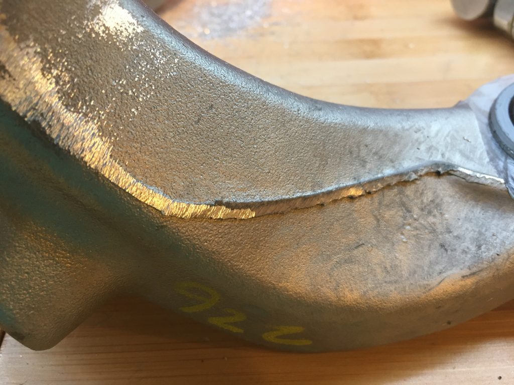
The IRS knuckles have a really sharp parting line from the casting process. I didn’t want to get cut working on the car, so I wanted to remove it. I used a carbide burr in a die grinder to take it down flush to the surrounding material (you can see the difference below between the left and the right side). After grinding it down, I used a scotchbrite roloc disk to smooth out the surface. This took longer than I expected, so I only completed one side.

Removed Body and Aluminum Panels

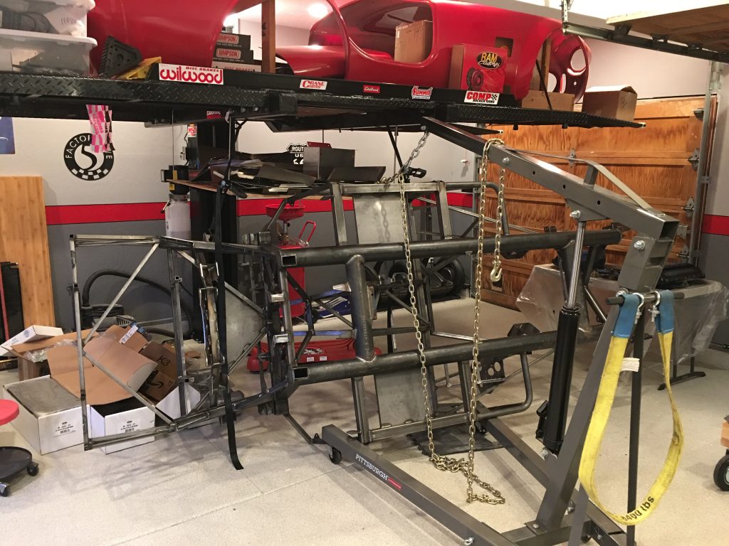
Jenn and I pulled the body off the car. It’s a little bit of a pain with only two people, but manageable.

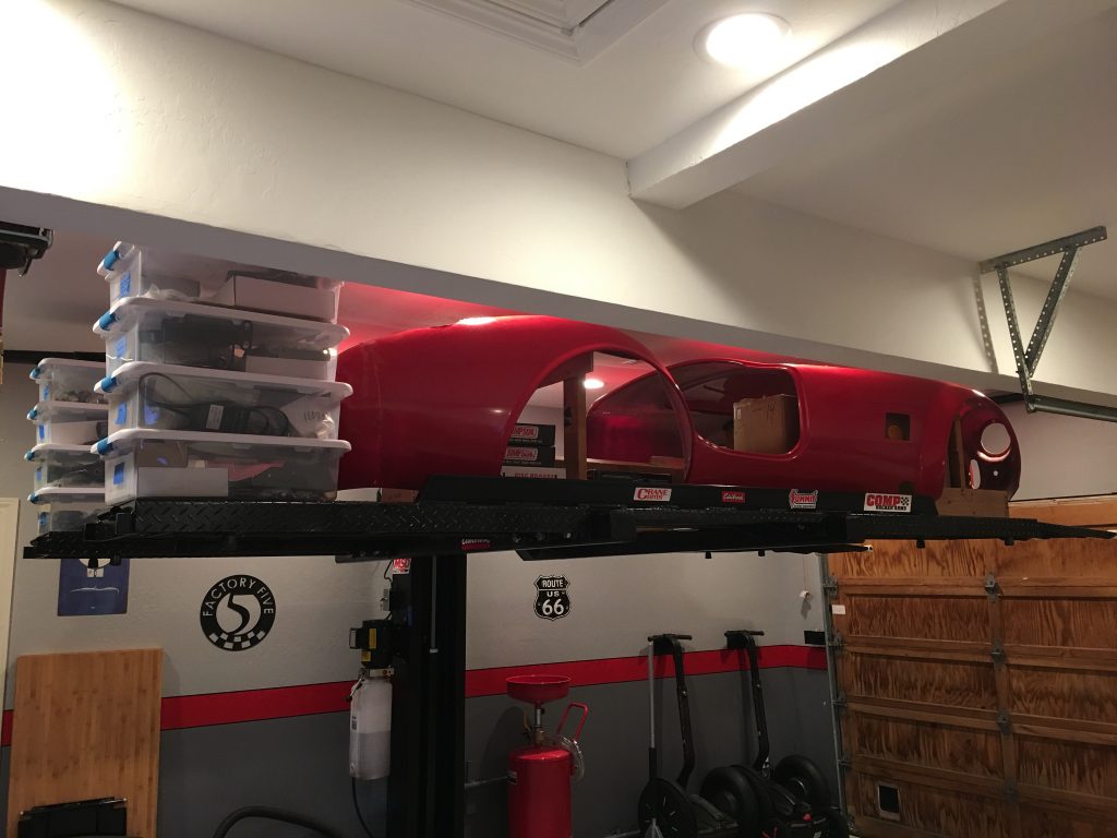
I built a really simple little body buck and put the body up on the lift. There’s plenty of room under and around the body to store most of the parts.

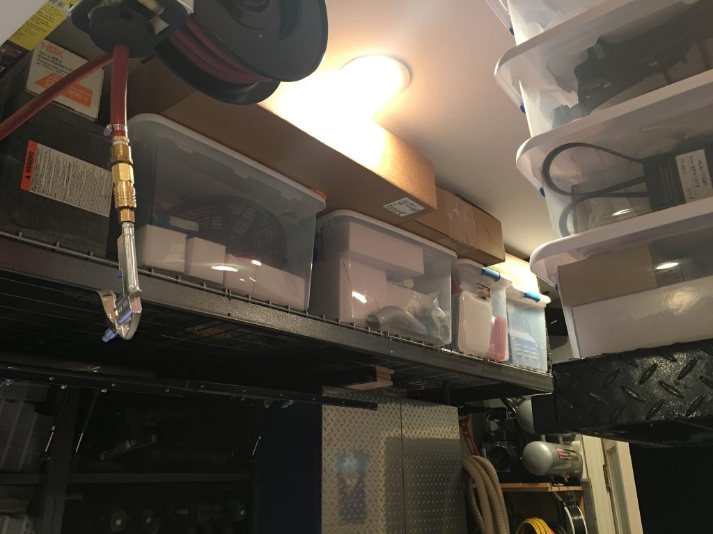
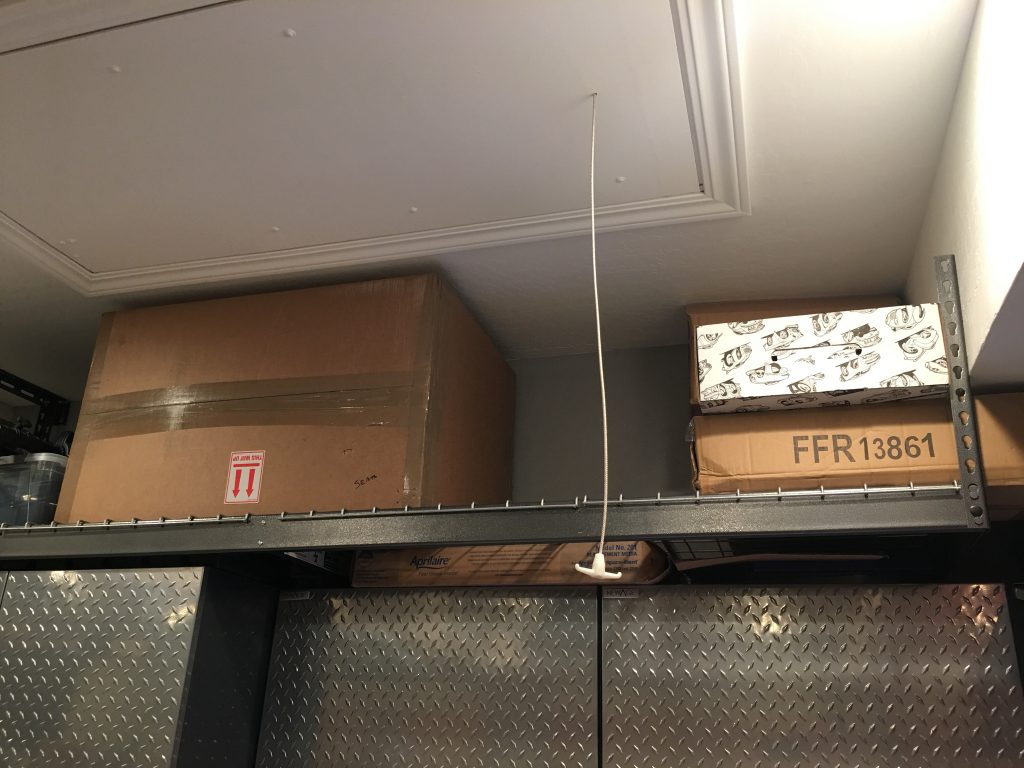
The rest of the parts are tucked up on our overhead storage racks.

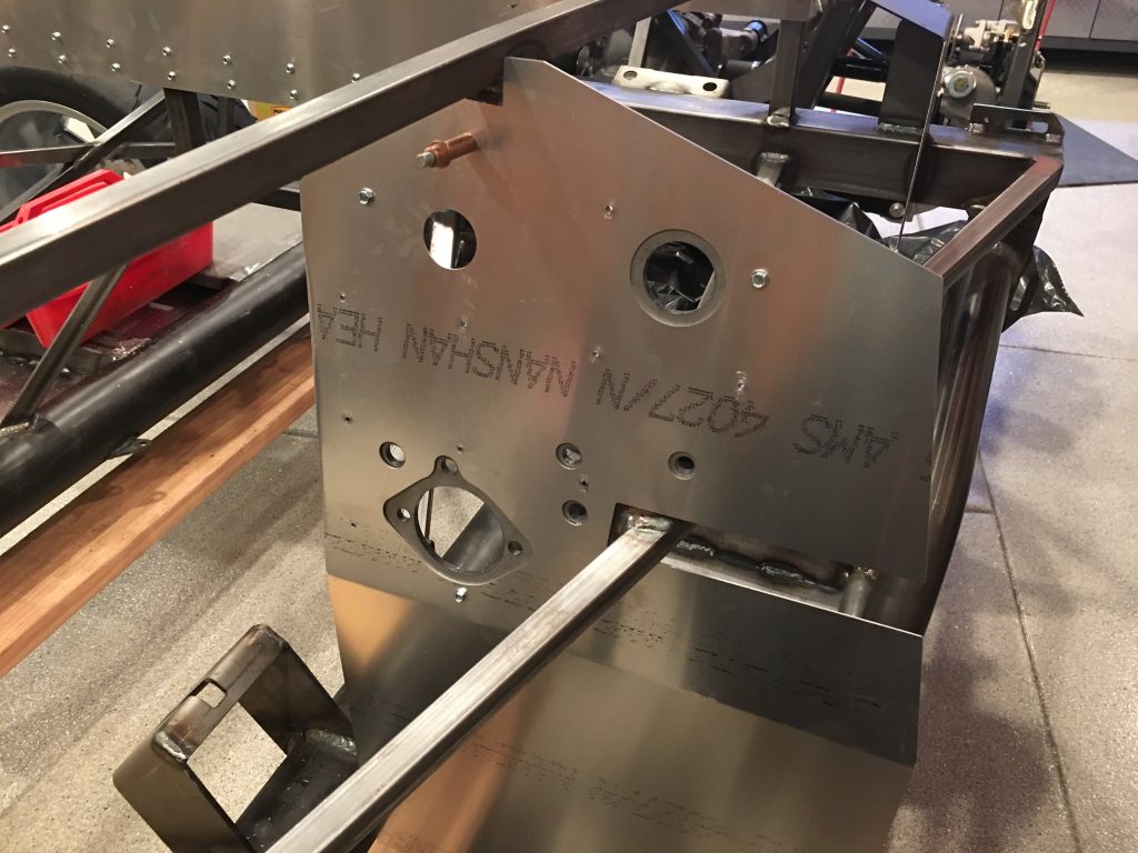
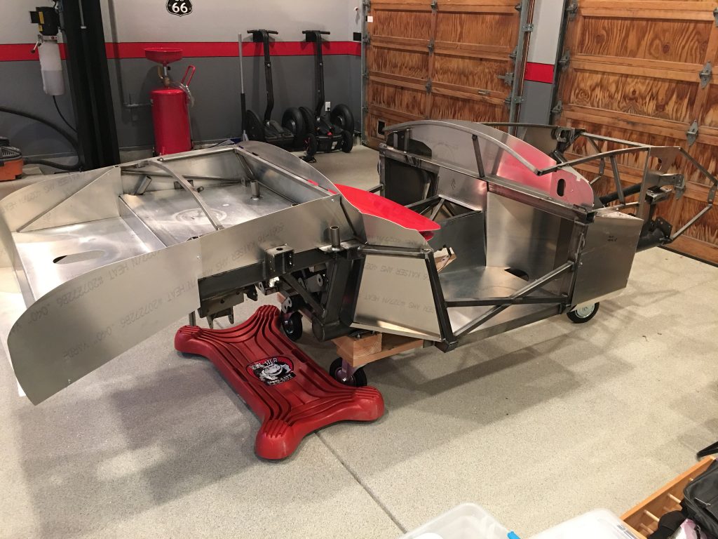
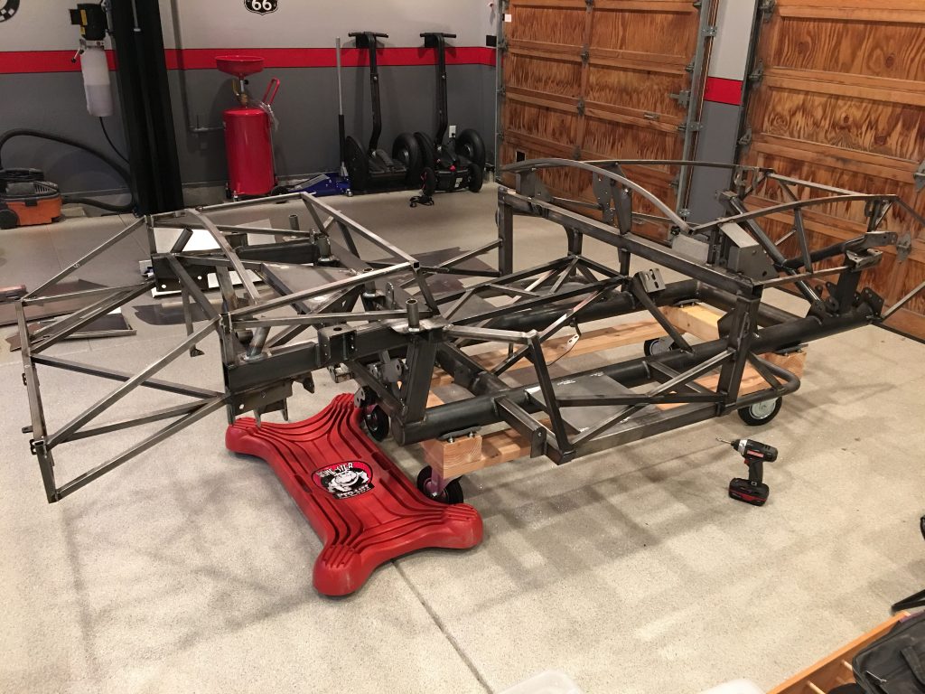
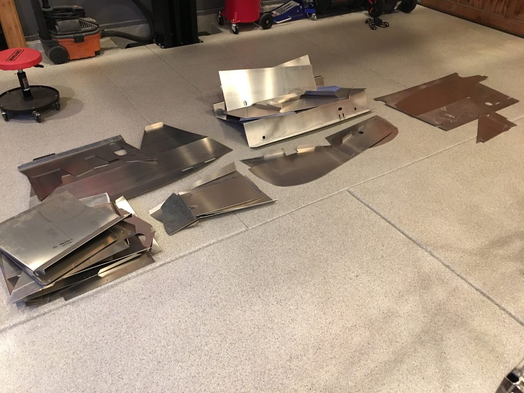
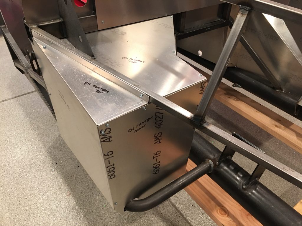
After inventorying all of the aluminum panels and jotting the name on those that aren’t obvious, I pulled all of the panels off of the chassis.

I have quite a pile of aluminum that I need to find a place to store.

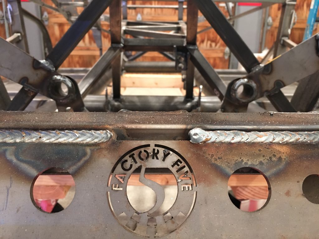
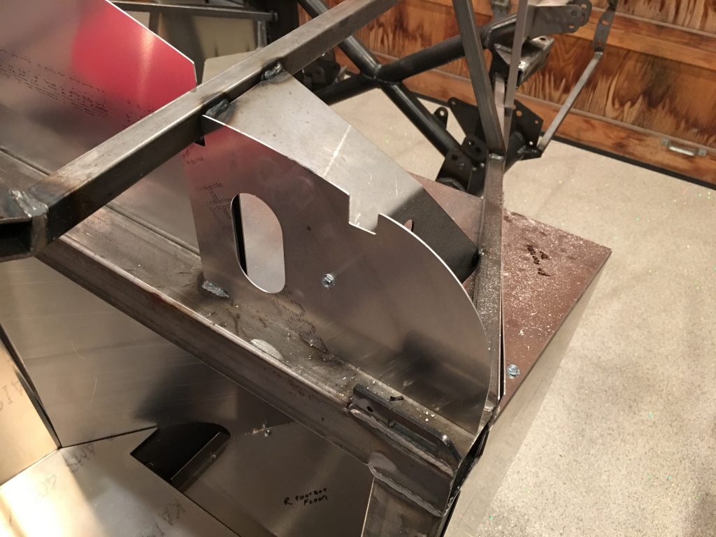
The chassis is really a beautiful piece of work. They even included little details like their logo laser cut into part of the chassis in a place that virtually no one will ever see.
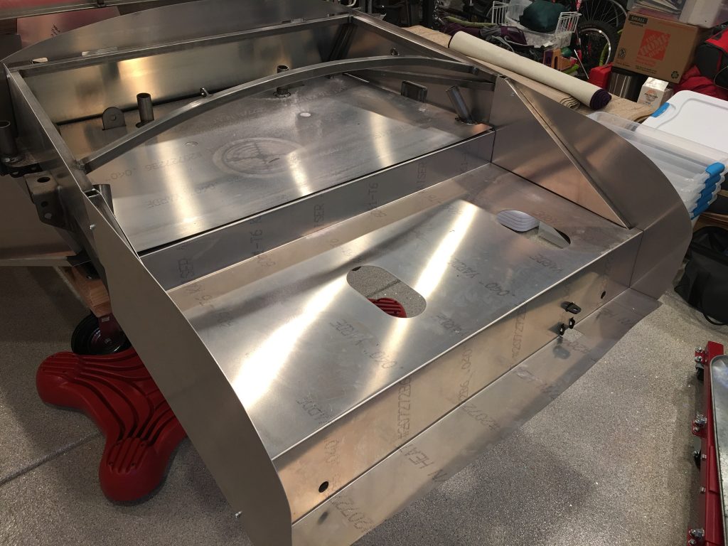
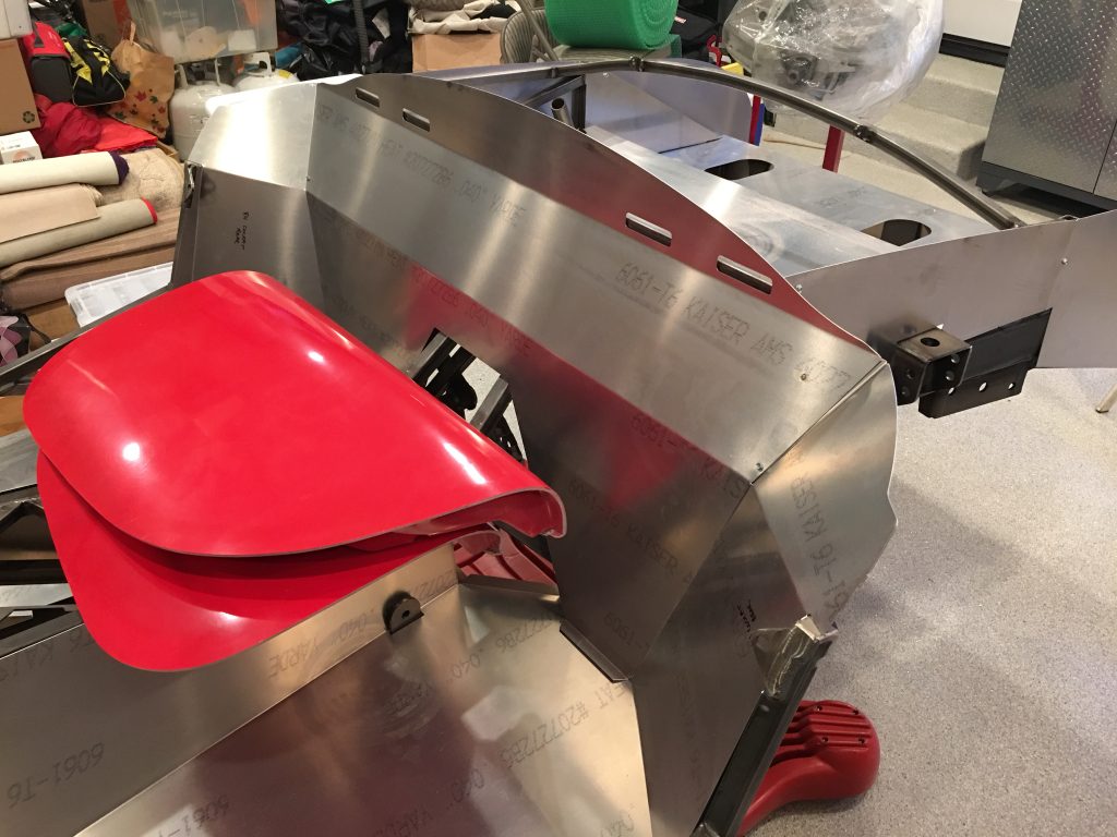
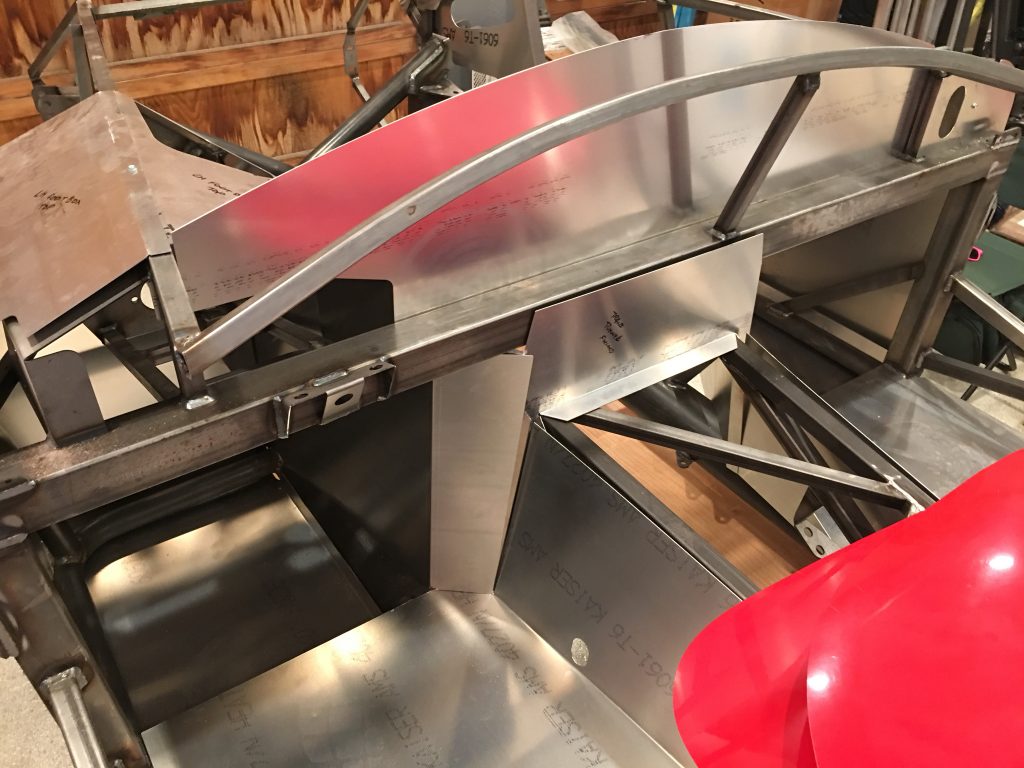
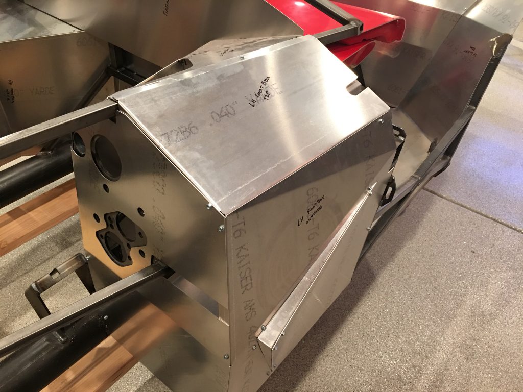
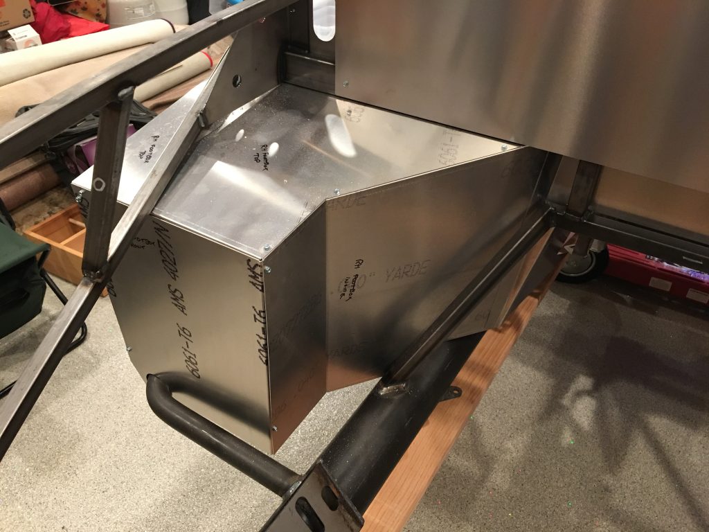
The rest of the pictures are just a reference for us to refer back to when reassembling the chassis aluminum panels.