Fit Fuel Tank

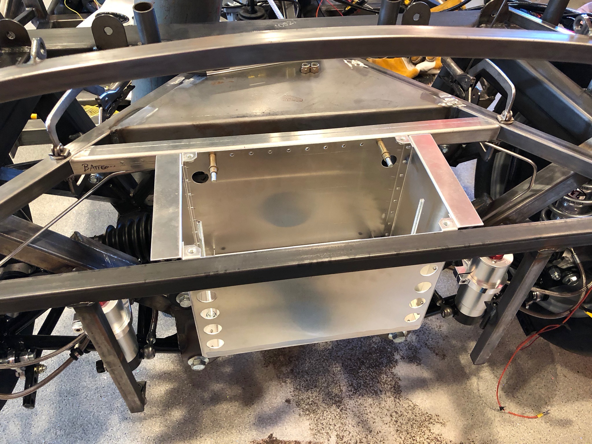
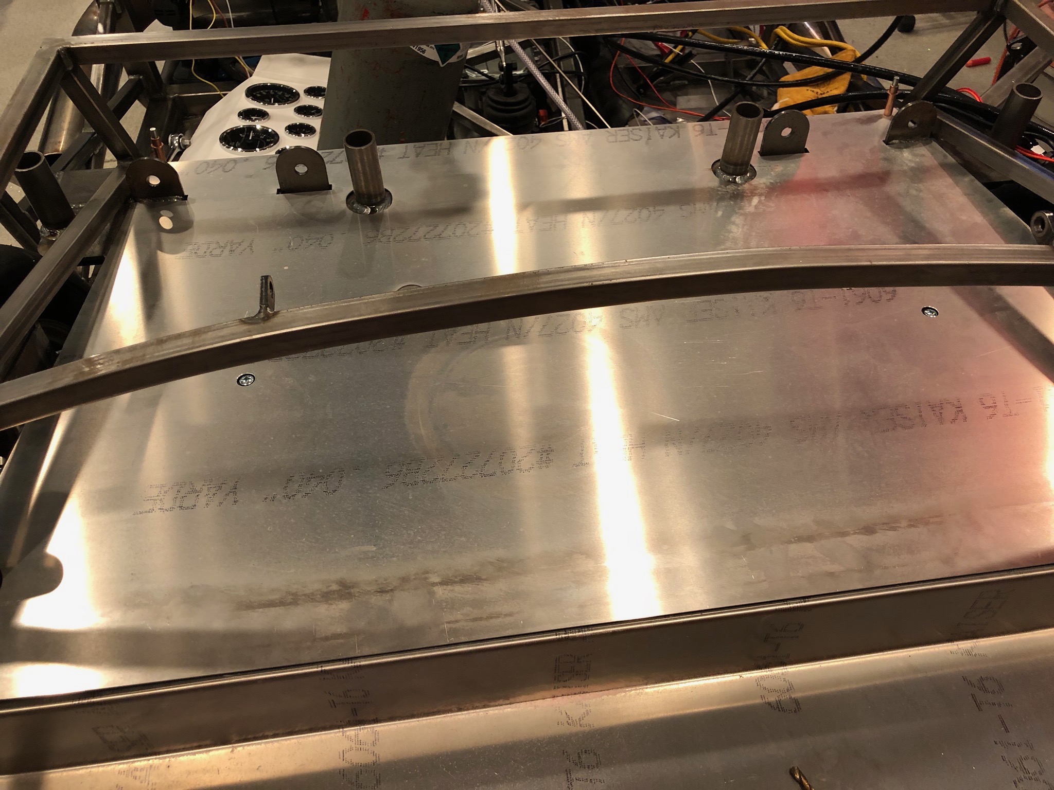
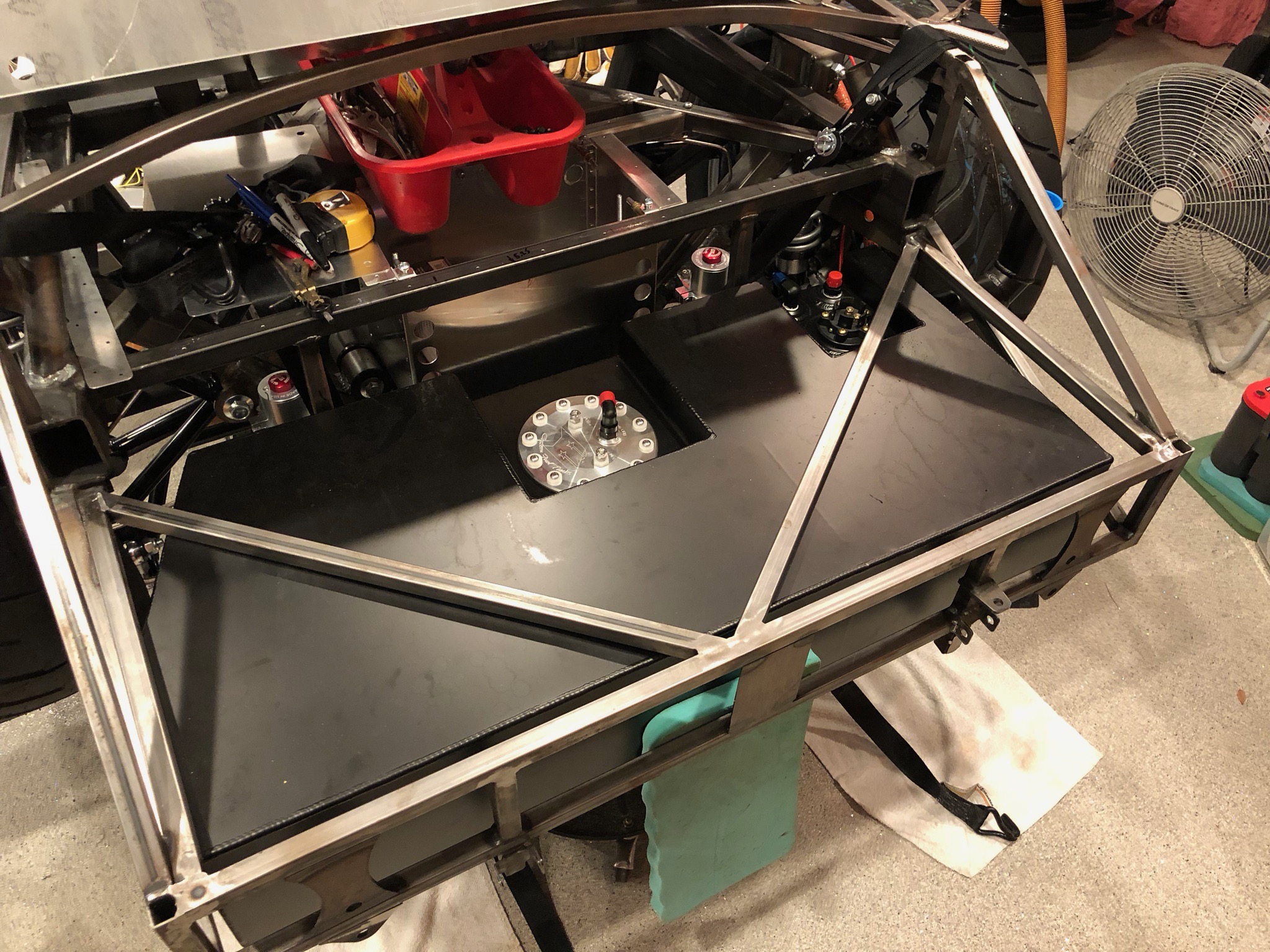
I test fit the fuel tank because I need to cut new access panels in the lower trunk floor. The fuel sender sticks above the top of the tank, so I needed to shift the tank most of the way forward and slightly left of center in order for the sender to clear the right diagonal square tubing.

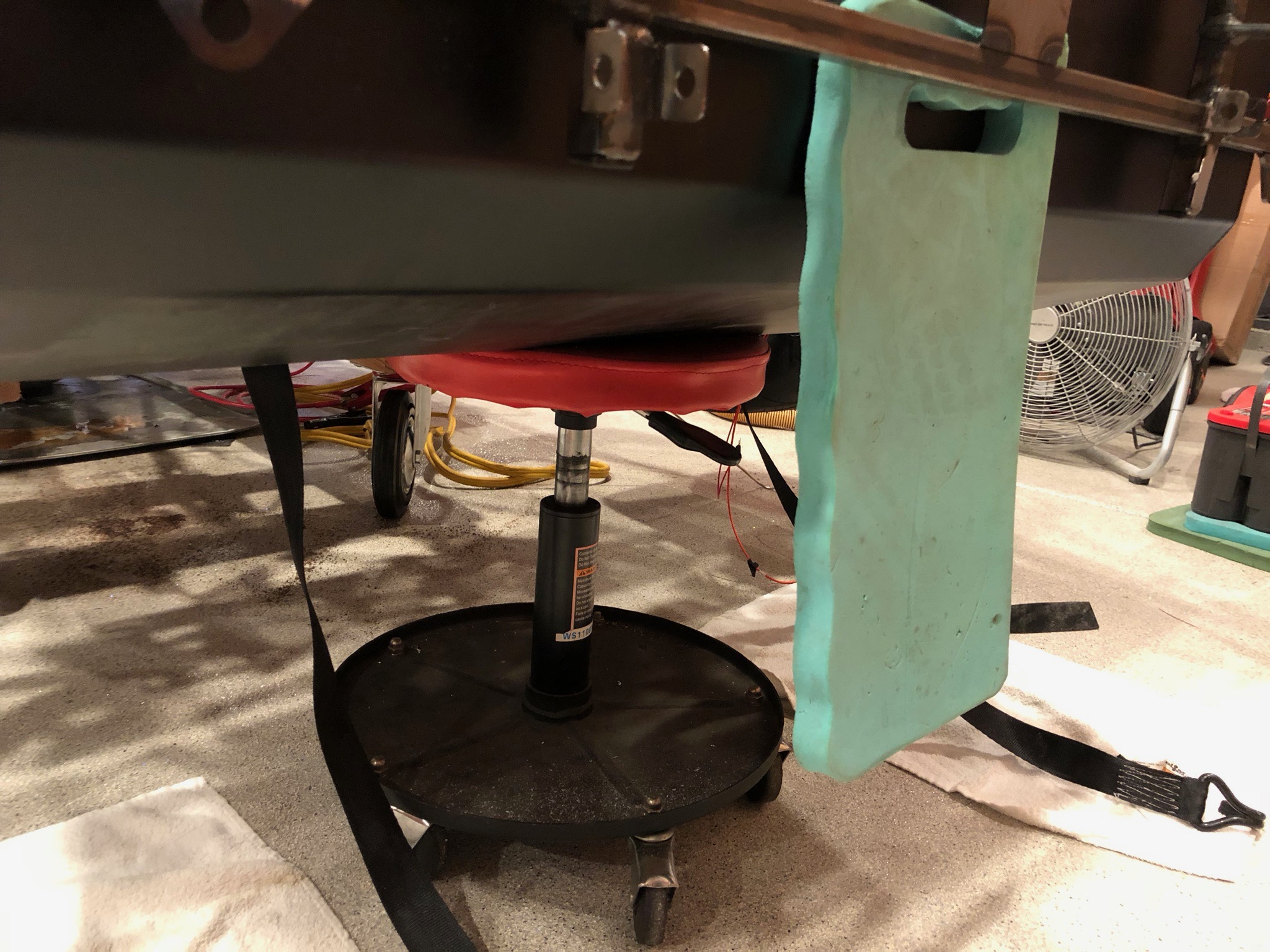
I temporarily supported the tank with my pneumatic stool and removed the straps so that I could install the lower trunk floor.

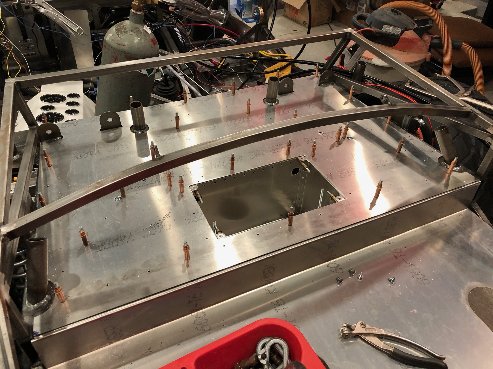
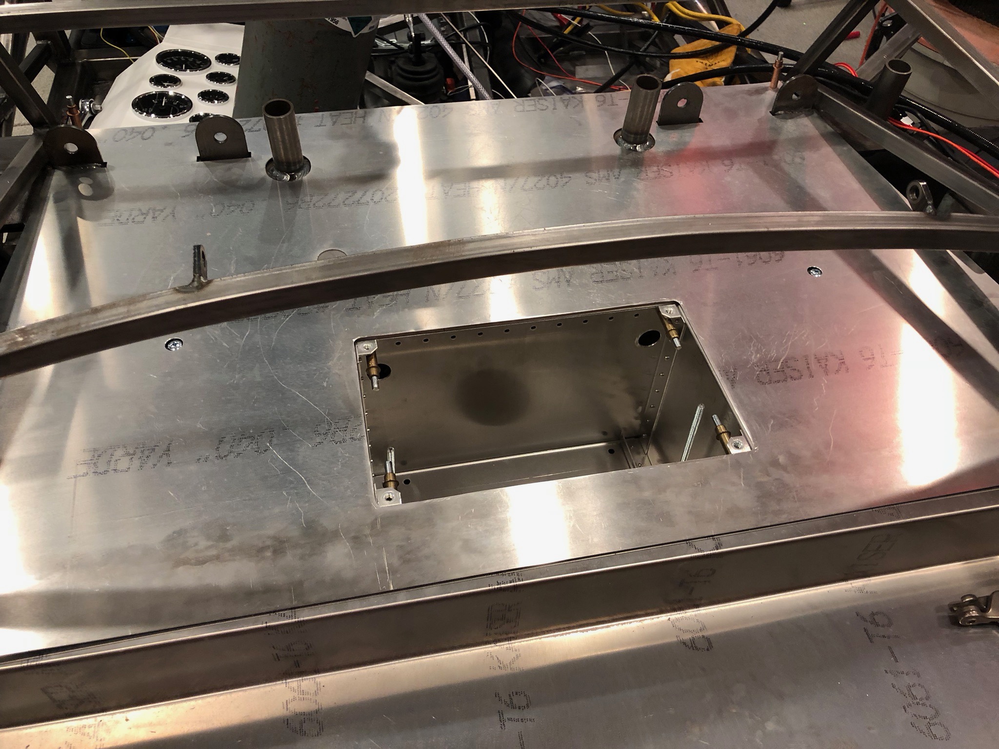
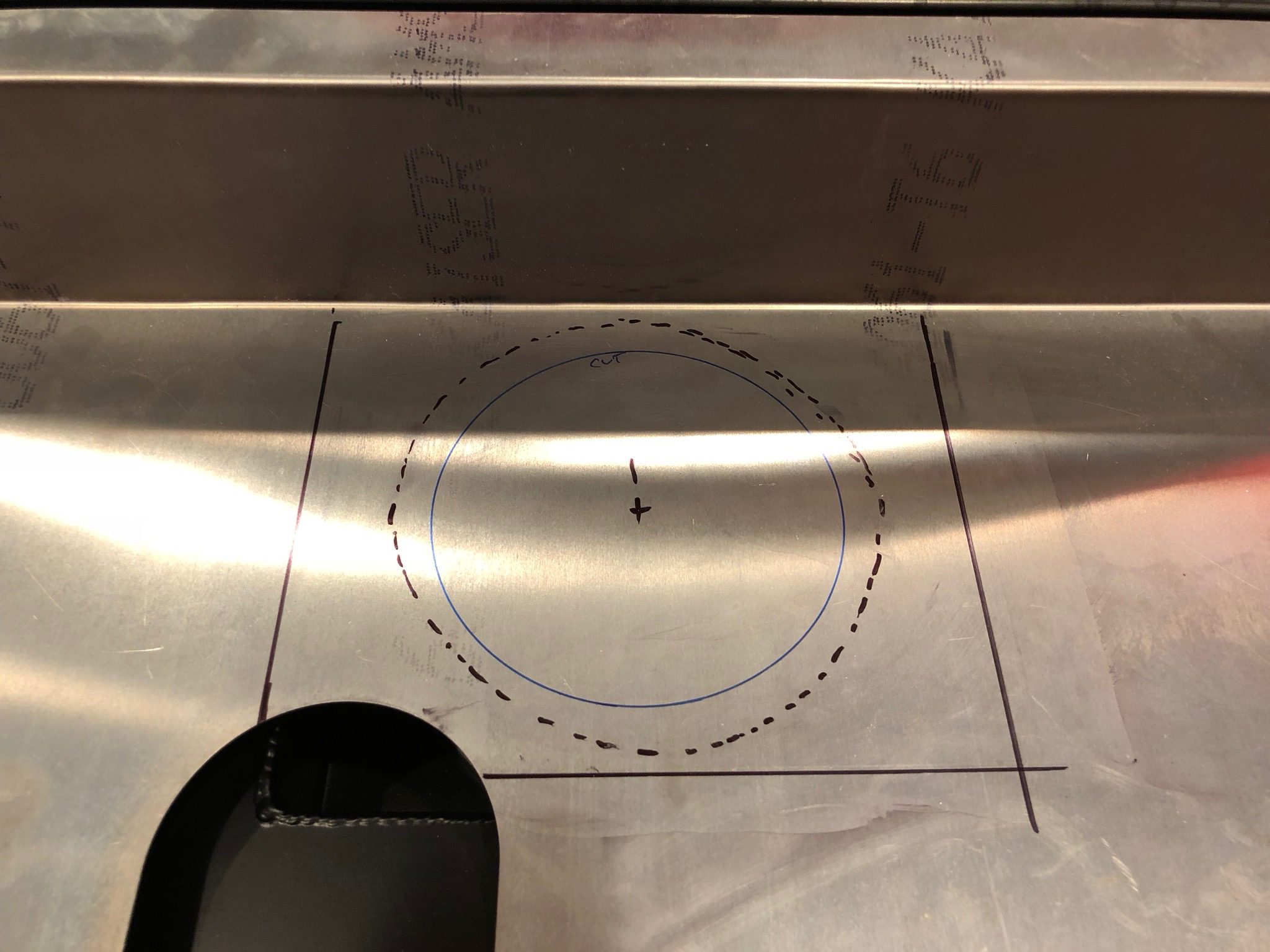
With the floor installed, I marked the location of the new access panel for the fuel pump. I’ll probably make this slightly bigger so that I can remove the fuel pump through the hole if that ever becomes necessary.

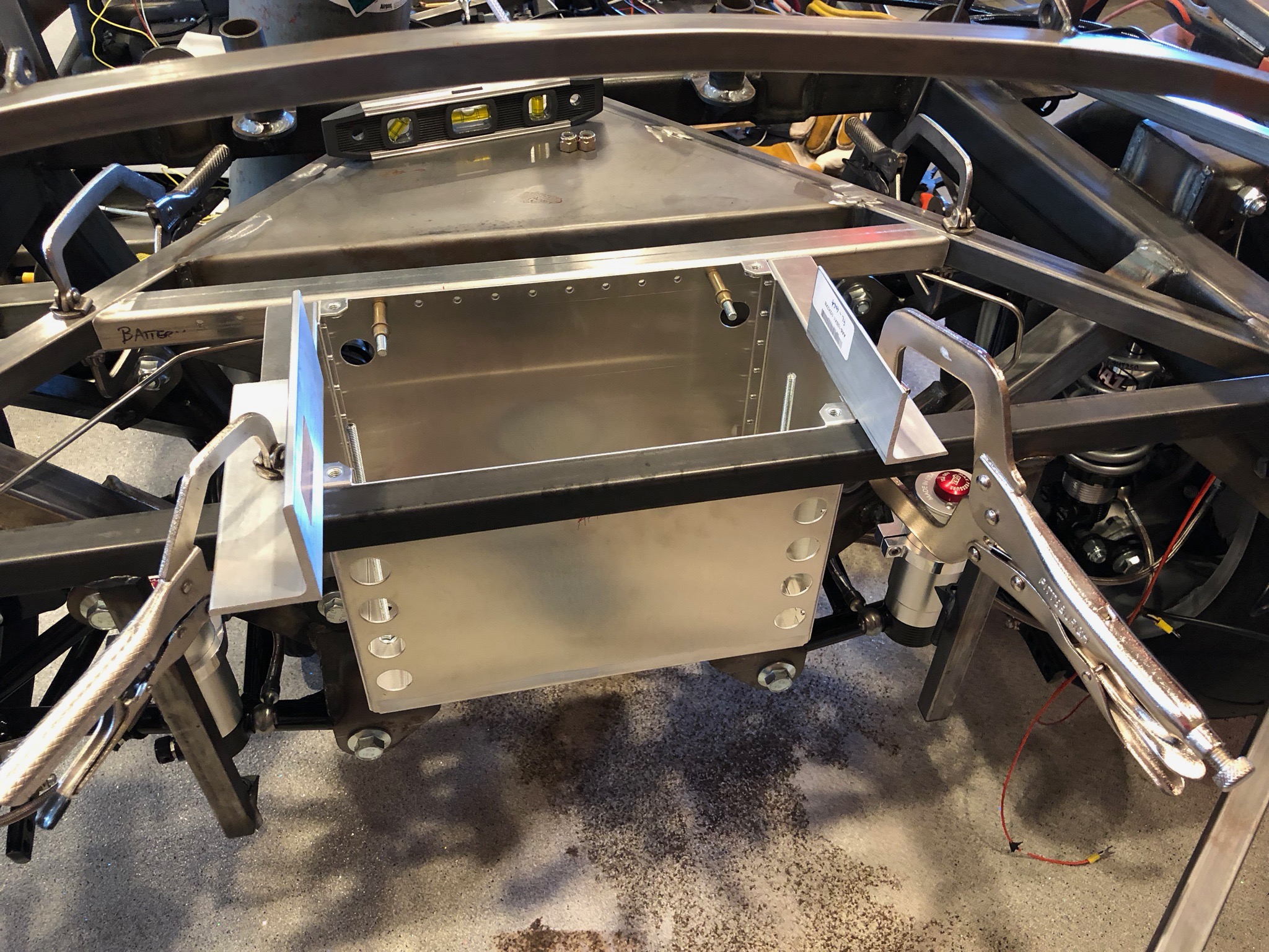
I also laid out the hole for the access panel that covers the fuel level sender, fuel return and vent fittings. This access panel will wrap up the vertical portion of the lower trunk floor since the plumbing fittings are forward of this surface and would be difficult to access only through the lower portion of the hole.

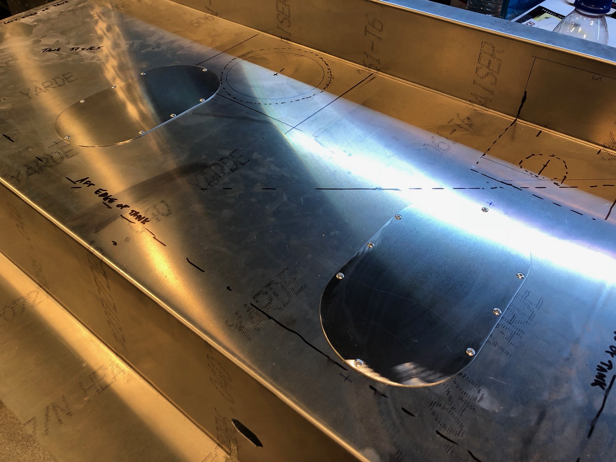
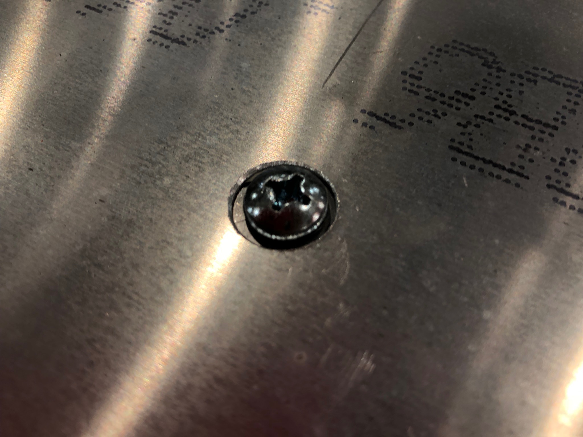
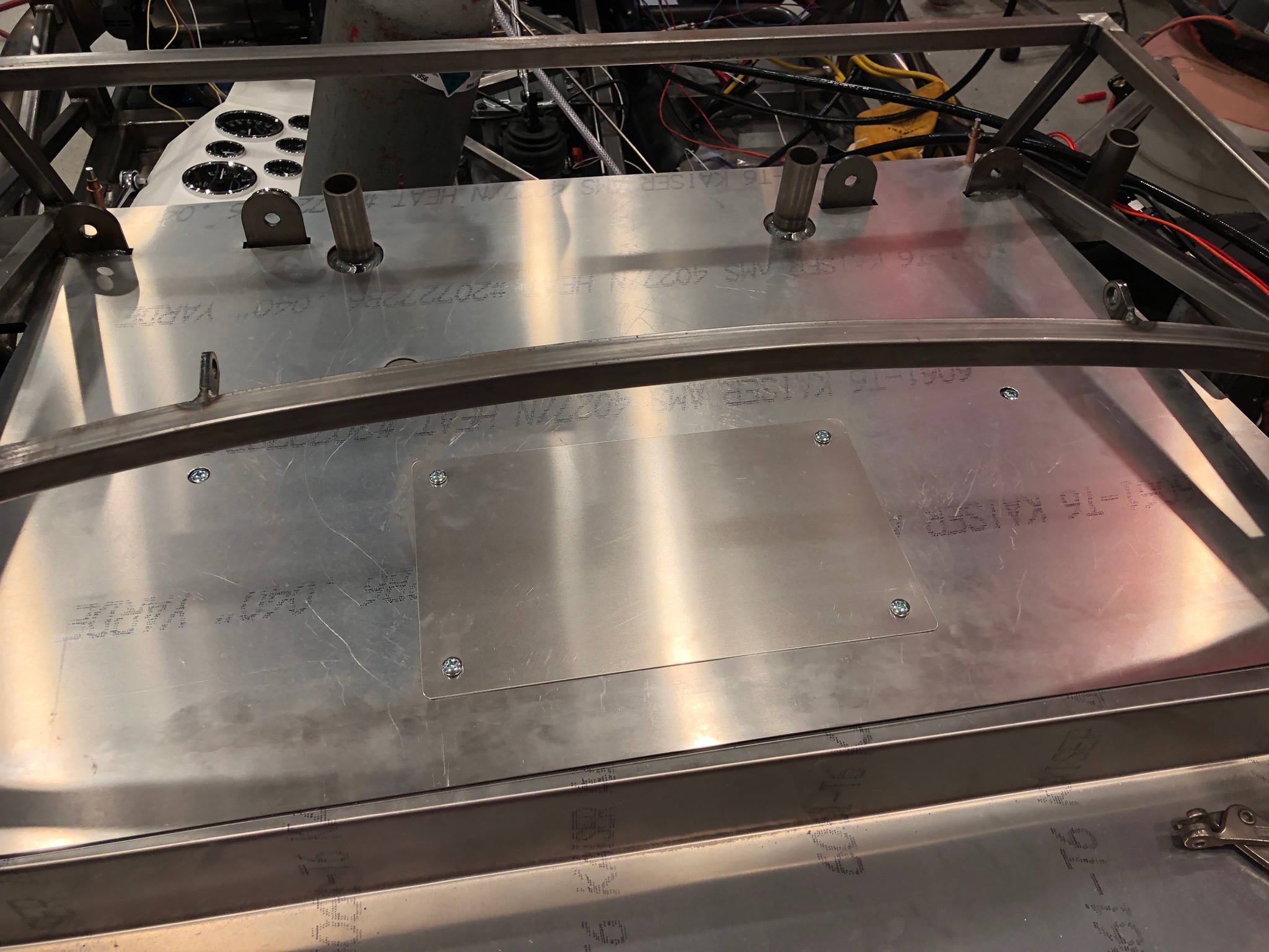
Since I don’t need these access holes, I made sure the rivets wouldn’t interfere with the 3/4″ square tubing below and then drilled and riveted these plates in place.

Drilled Upper Trunk Floor

With the upper trunk floor in place, I reached underneath and traced around all of the supporting structure with a sharpie. I then removed the floor and laid out and drilled holes through the aluminum. Afterward, I repositioned the floor and match drilled the underlying structure.

Installed Battery Box

I decided to install the battery box. I disassembled it so that I could debur all of the edges and then riveted it back together. The forward cross bar needed a little trimming to fit between the angled square tubes. I then positioned everything in place and clecoed the box to the cross bar.

After verifying that the box clears the diff mounting ears, I clamped some straight edges to the flanges of the battery box to make sure it was flush with the aft square tube. I then drilled the box to the aft square tube and drilled the cross bar to the angled square tubes.

After positioning the floor in place, I drilled a couple of holes at the forward corners to lock in the position, then marked and drilled the holes that clear the bolt heads holding the cross bar in place.

The bolt heads still stick up above the floor slightly, but all of this will be covered by carpet.

I reached up through the bottom of the battery box and marked the edges for trimming. After cutting out the hole, I test fit the floor in place.

The hole will be covered by a plate that is also held down with button head screws. I briefly considered making these use flush head screws, but I don’t think the extra effort is worth it.

Finished Steering Linkage

I cut the tie rods so that I could thread on the bump-steer linkage. Despite the steering rack being centered, I needed to cut off 1/2″ on the right and about 1 1/4″ on the left. This lets me thread the bump-steer linkage on fully and have a bit more toe-in than you’d ever want.

The bump steer kit from Fortes Parts has a tapered shim that fits around the bolt and fits up into the taper in the steering arm, but it doesn’t look like it fits all the way in. I don’t think this is a problem, but I want to run this by Mike Forte just to be sure.

With the linkage complete, I pulled the boots back in place and zip-tied them in place.

Installed New Driveshaft

I received the new shorter driveshaft from FFR today. This one is 3/4″ shorter than the old one, so it should fit fine.

I had to loosen the engine mount bolds and remove the lower transmission mounting bolts in order to shift the transmission to the left enough to slide the slip yoke over the transmission output shaft. I then slid the aft flange in place and installed the bolts. Given the mechanical advantage of the diff, I couldn’t hold the rear wheel in place firmly enough to torque these bolts, so I put the transmission in gear to prevent the driveshaft from rotating.

The driveshaft is just short enough that the seal rubs on the slip joint instead of the face of the u-joint.

Initial Idle Adjustment

I turned the idle adjustment screw in a half turn and fired up the engine. It was still idling fairly low, so I continued turning it in until it was idling around 1500 rpm and let it warm up. After it was warm, I started turning the idle down until the Idle Air Control (IAC) was between 3-10. Unfortunately, I blew the lower radiator hose out of the rubber tubing connecting it to the radiator and dumped the coolant. I really dislike the corrugated hose from FFR; I’m going to replace it with some rigid tubing from Breeze Automotive.

Finished Reassembling Engine

I finished reassembling the engine and then did an oil change, refilled the coolant system and installed new spark plugs. Jenn did the honors and the engine fired up immediately. The idle still isn’t set right, so you needed to hold the throttle open slightly to keep it running. It was getting late, so we shut it off for the night.

Started Engine Reassembly

Jenn and I started the engine reassembly tonight. We started by thoroughly cleaning the heads and deck and then torquing them down. After reinstalling the pushrods, and rocker arms, I installed the intake manifold gaskets with some gasket sealant to hold it in place while installing the intake manifold.

After applying some RTV to the china walls, I installed the intake manifold, throttle body, water neck and rocker arm covers. We should be able to fire up the engine this weekend.

Prepped Cylinder Heads

My dad dropped off the cylinder heads today. Fortunately, resurfacing them did remove most of the damage. I removed the valves and cleaned up some more to make sure there were no protruding bits of metal.

I also inspected the valve seats carefully to make sure there was no damage. Fortunately, they were spotless.

I cleaned up the valves and inspected them as well. The mating surfaces looked perfect, so I reinstalled the valves in the head.

Finally, I cleaned all the RTV off the heads and then trimmed the new head gaskets to match the old ones.