Engine Build

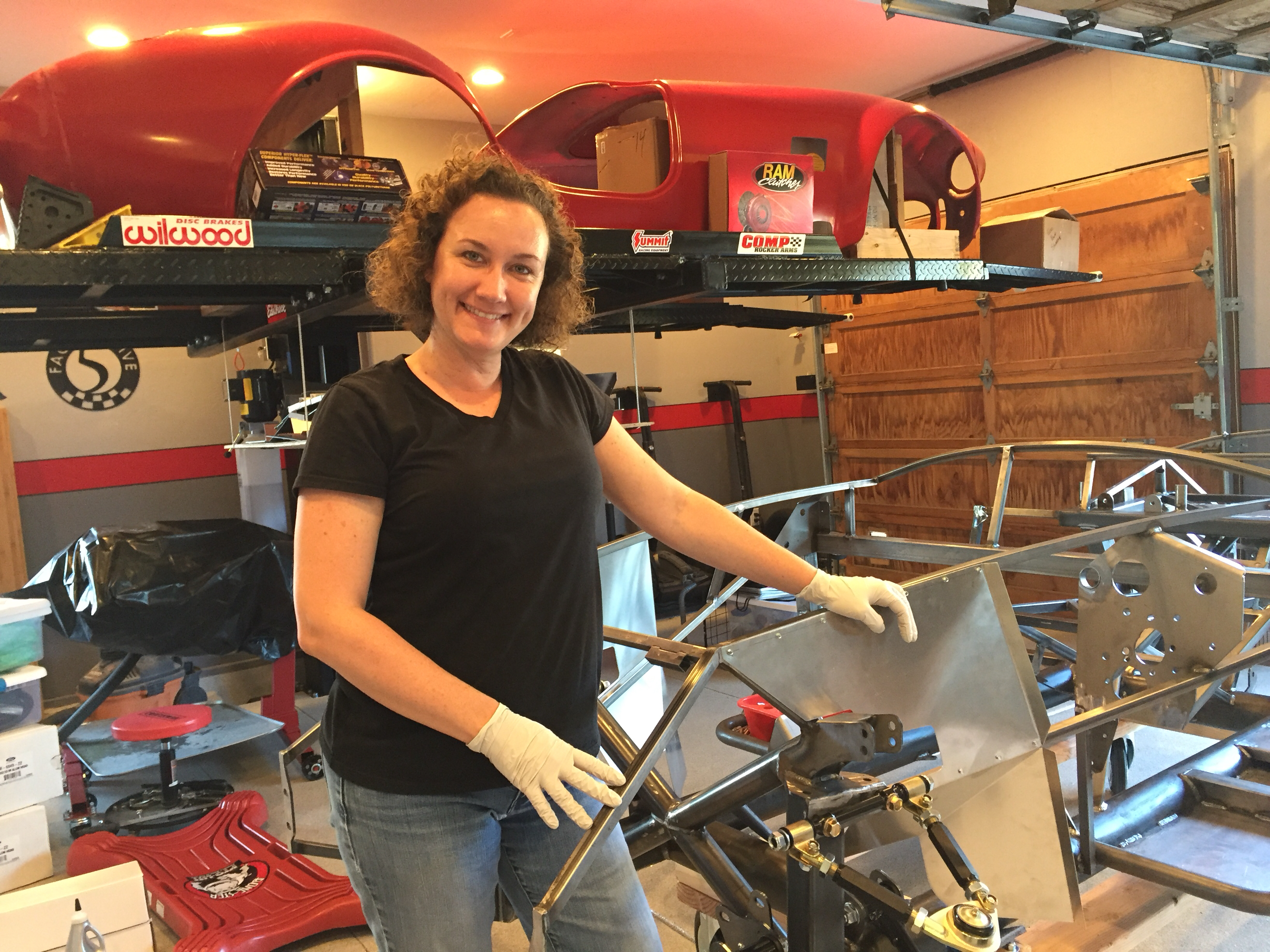
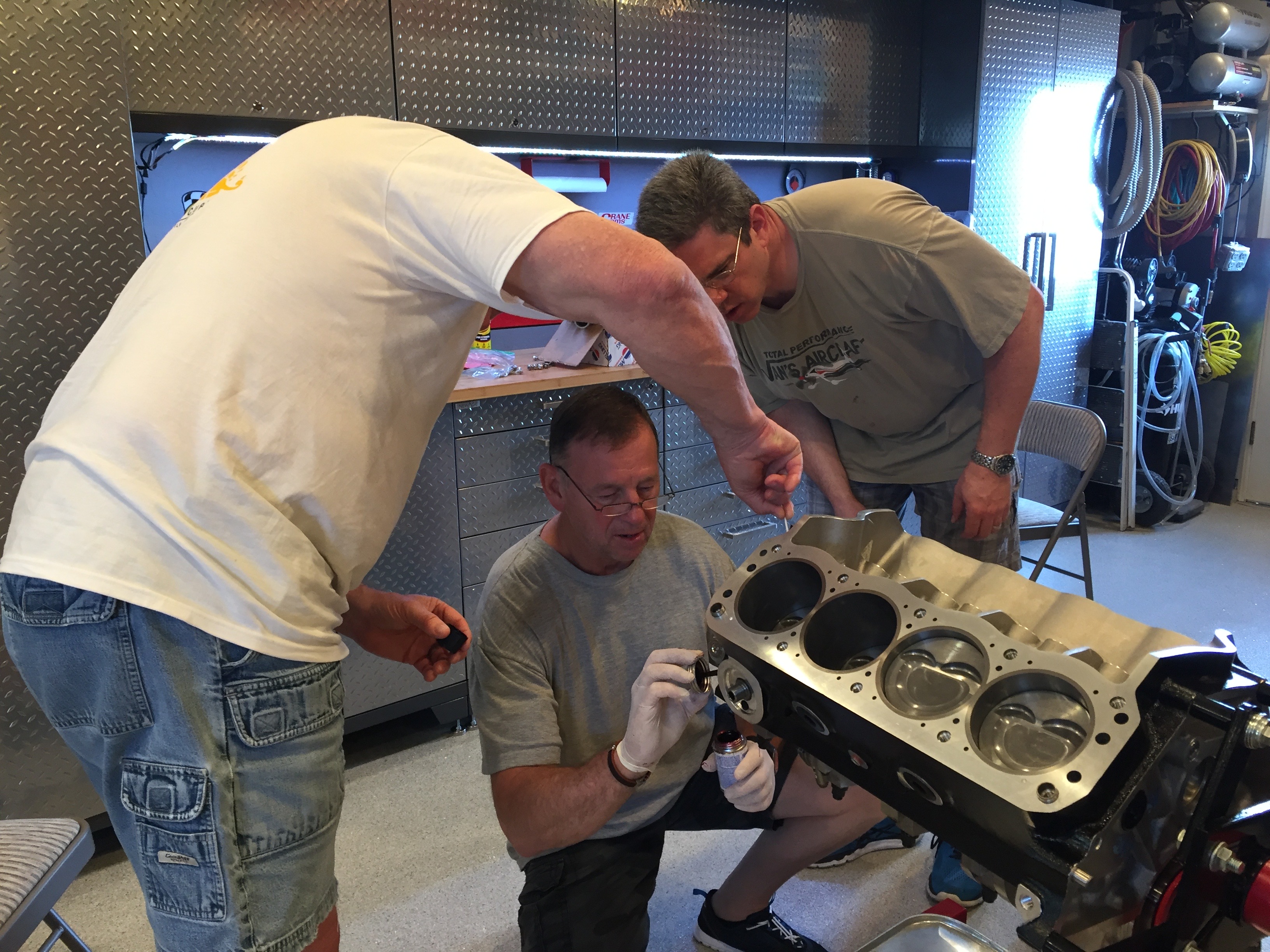
My aunt and uncle are in town this week at least in part so that my uncle could help us with building the engine for our Cobra. He’s done far more engine work than either my dad or I have and we thought it would be fun to all work on this together. We also scheduled this so that Jenn would be done with work and could assist with the build.

I put together a little video of the build, but I’ll also describe the process with pictures below.


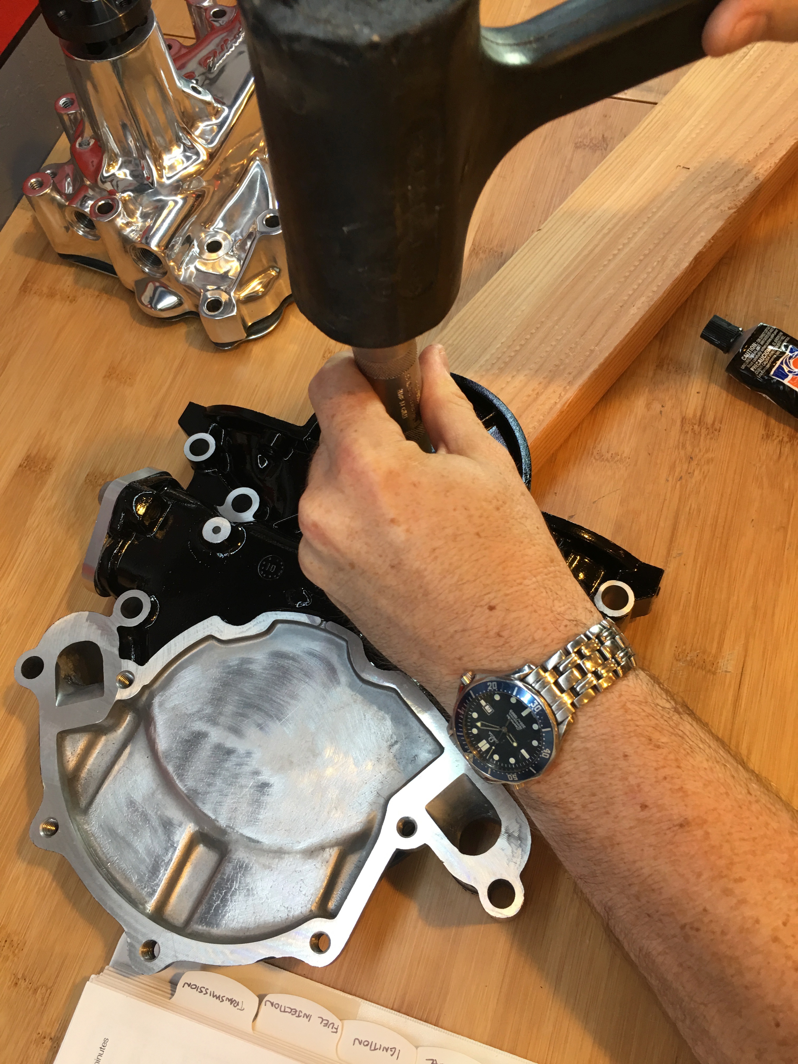
First up was to install the front seal in the timing chain cover. I put a thin film of RTV around the flange to ensure a leak free installation.

I then used a seal driver to seat the seal in the cover. This was a surprisingly tight fit and required a fair amount of force to seat.

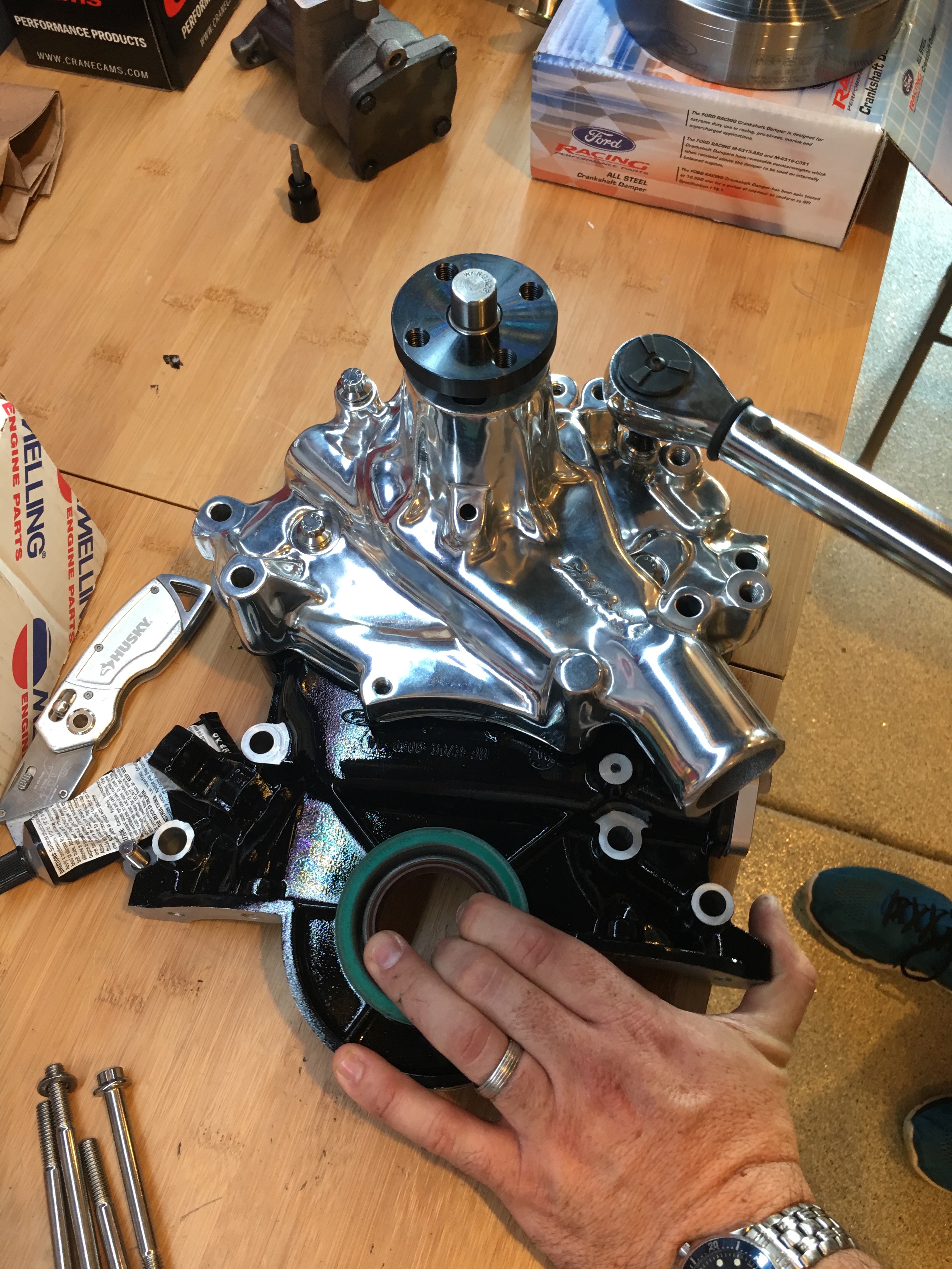
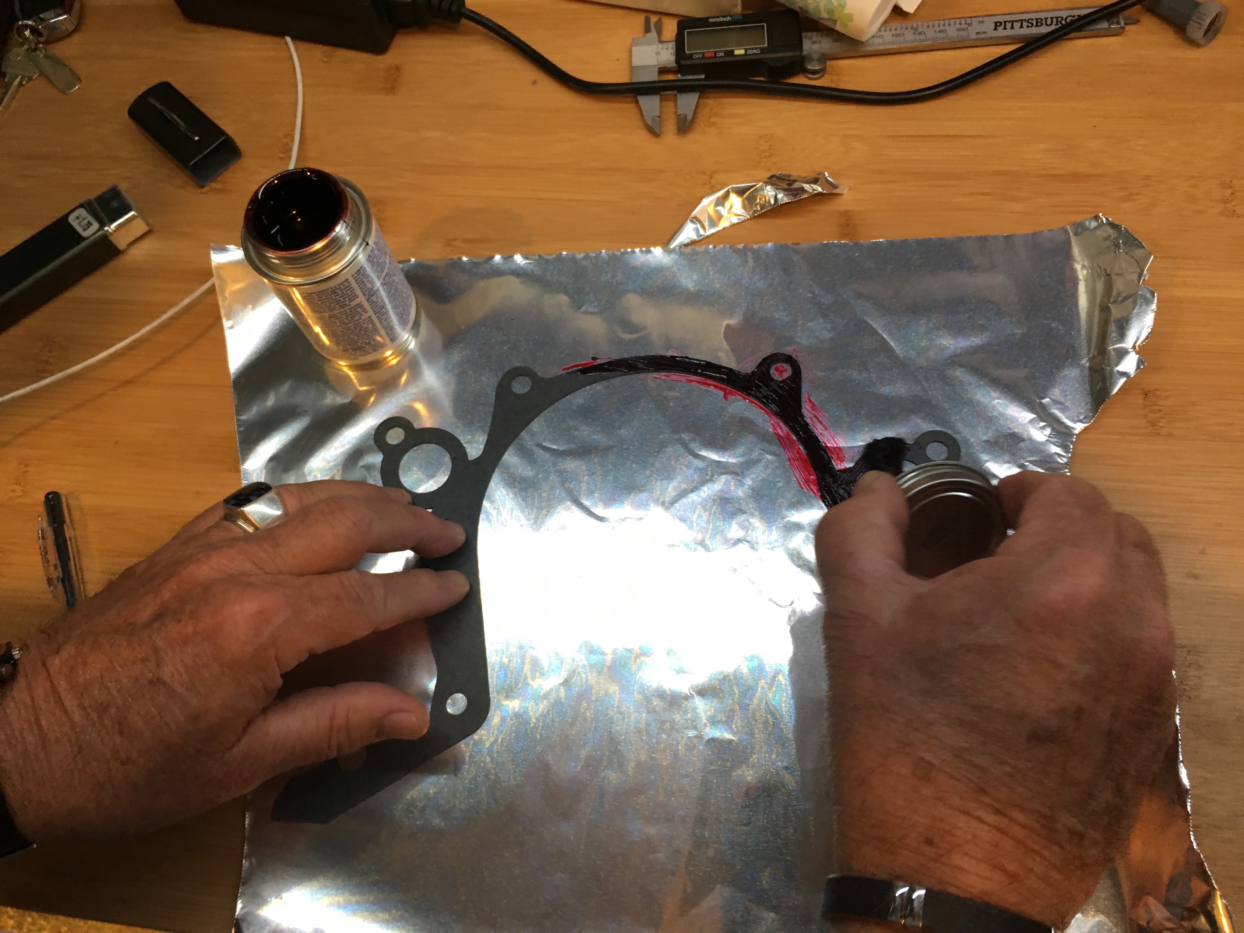
Next up is to install the water pump on the timing chain cover. We applied a thin film of RTV to the mating surface.

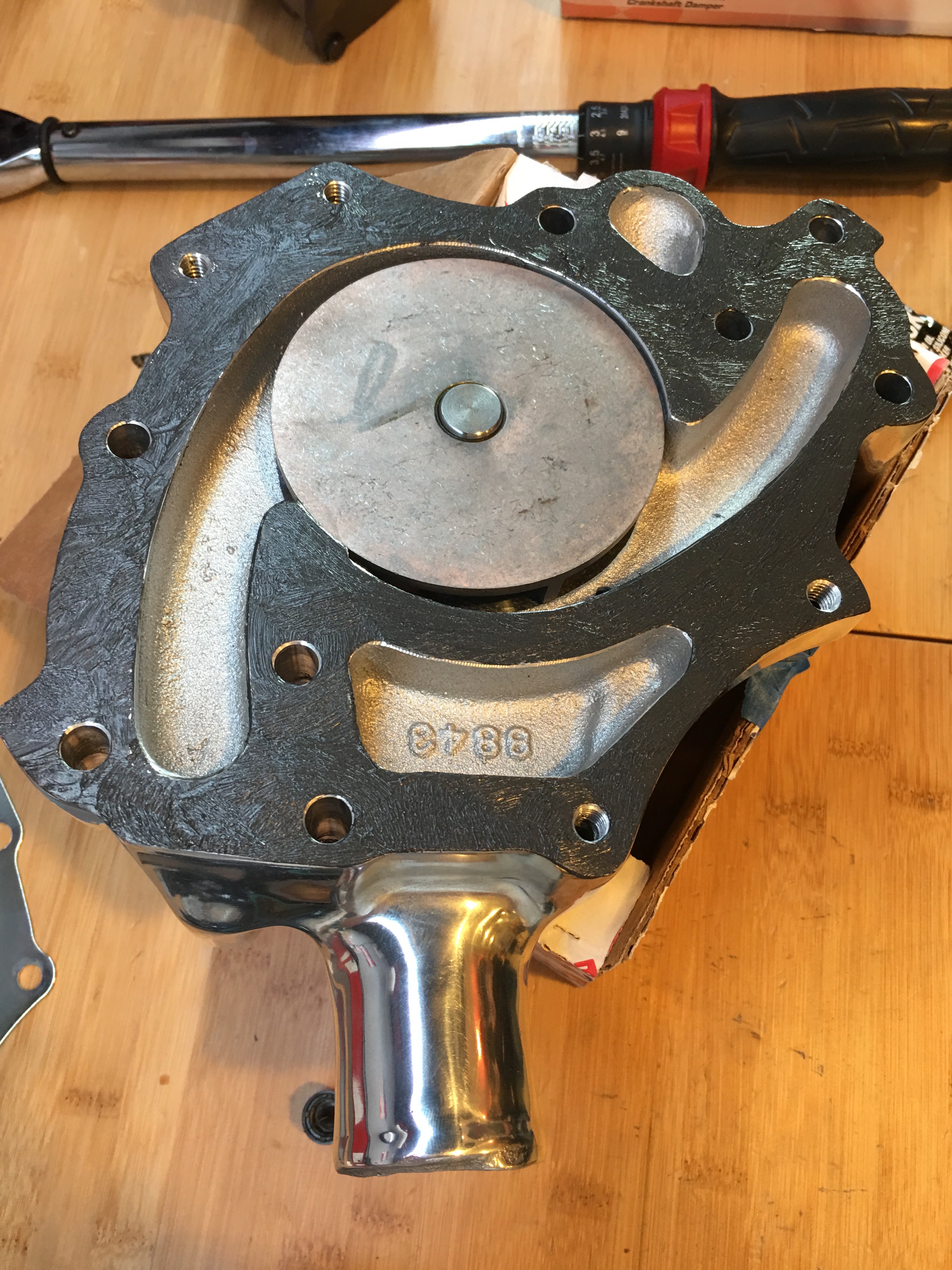
We installed the gasket and then applied a thin film on the other side of the gasket.

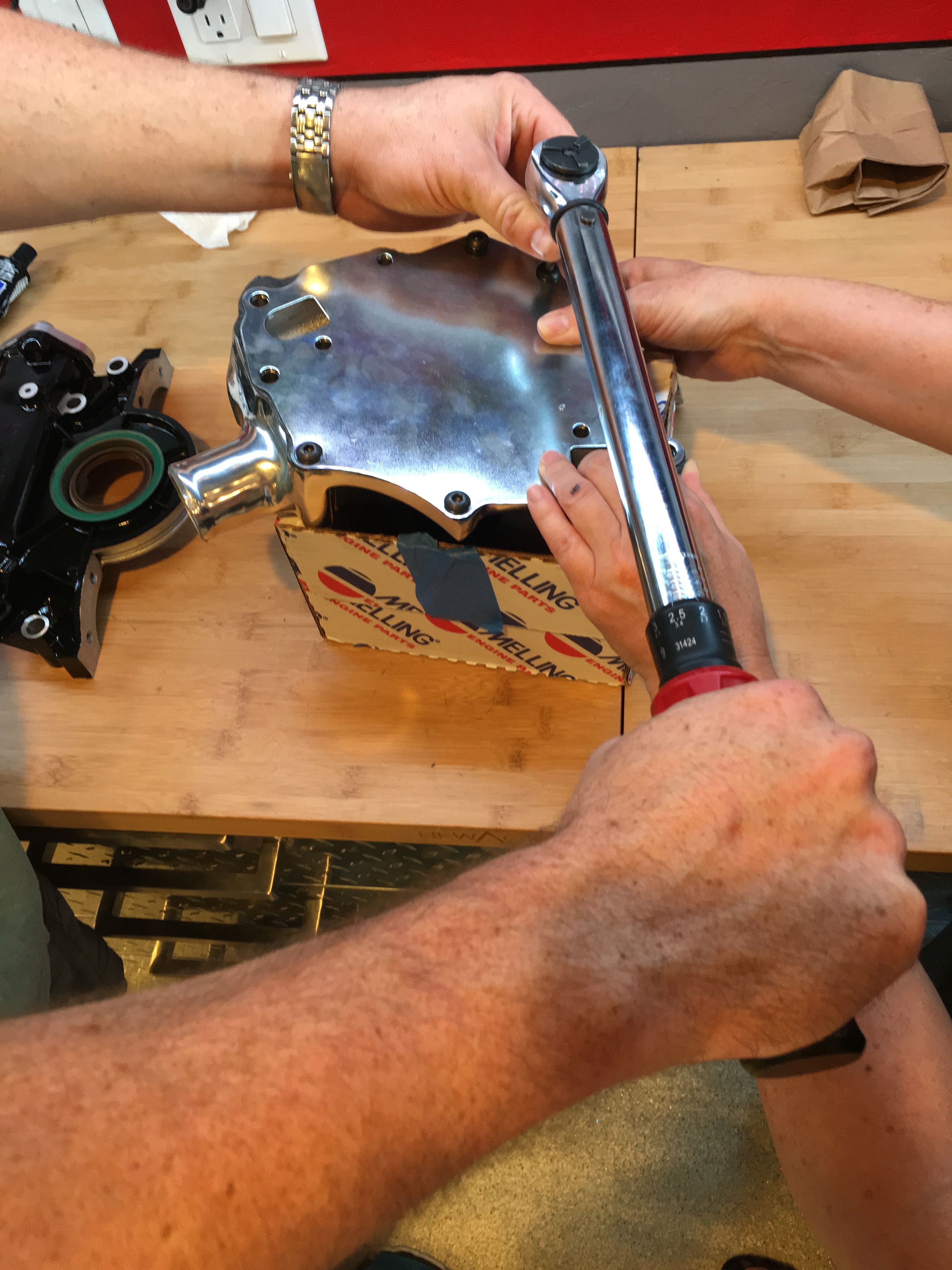
The water pump cover is installed and the upper and lower bolts are torqued.

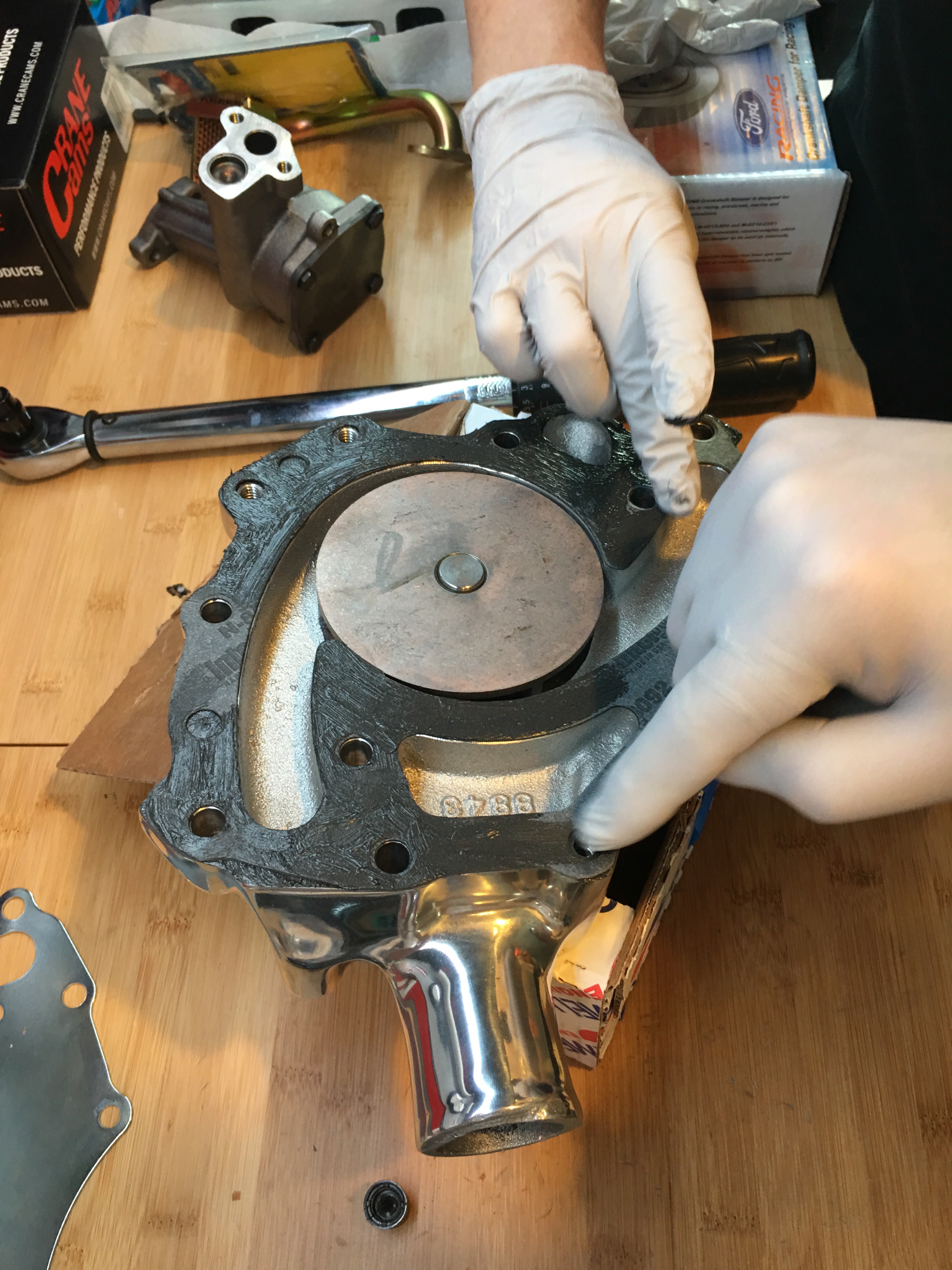
We then applied RTV to the timing chain cover and gasket before mating it with the water pump.

There are a few bolts that attach the water pump to the timing chain cover. The rest go all the way through the timing chain cover and into the block.

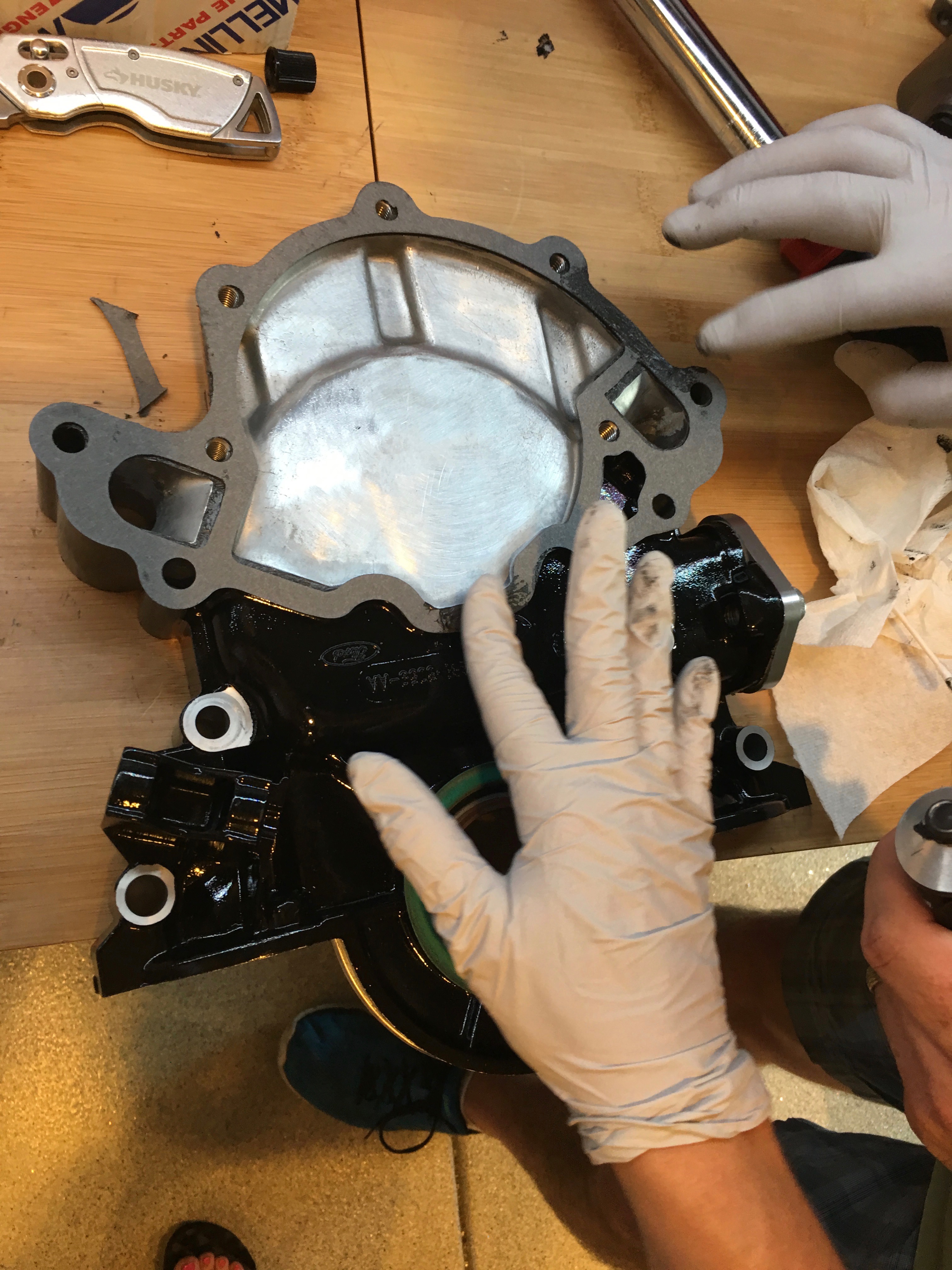
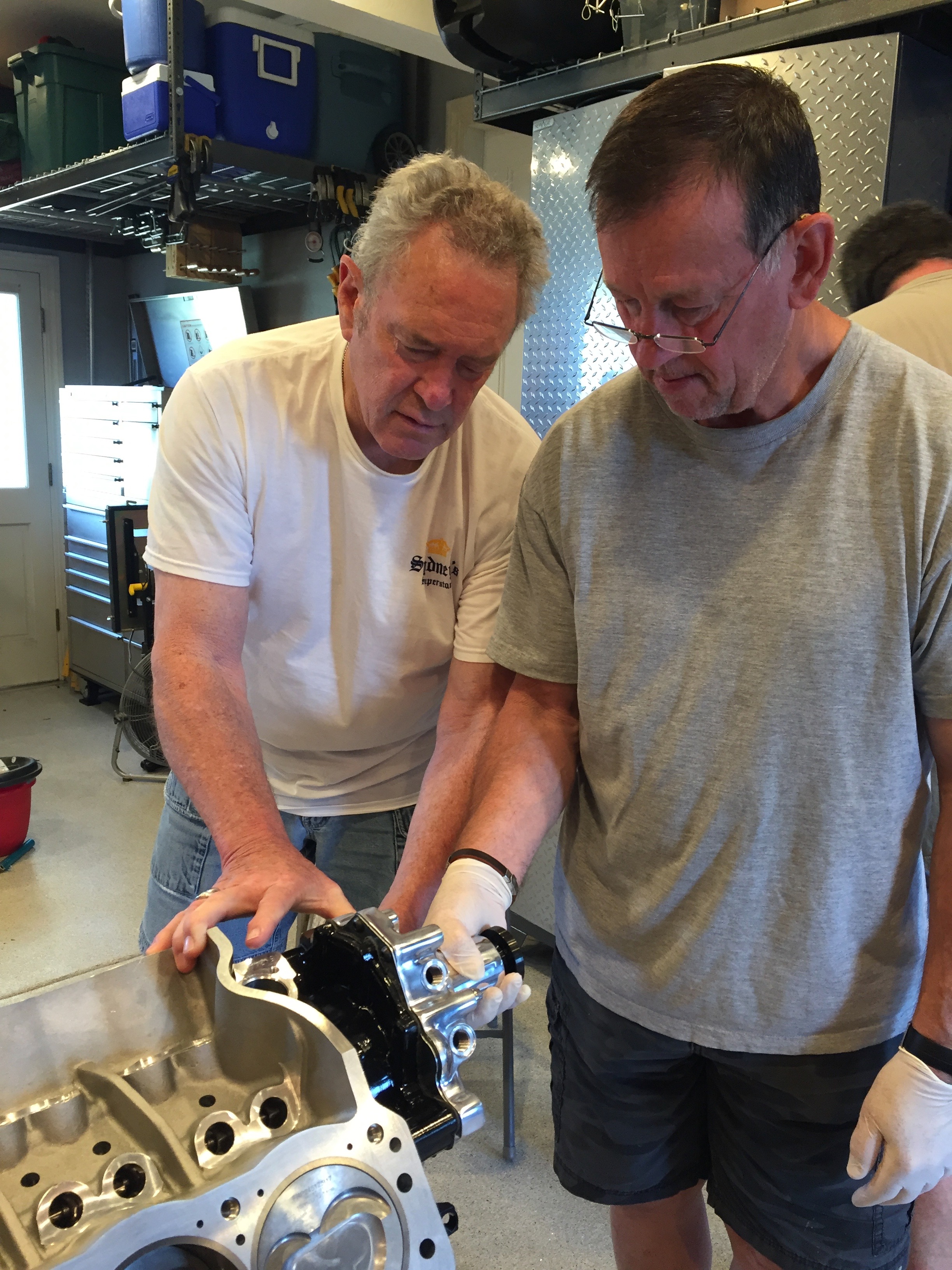
My uncle applied some high-tack sealant to the timing chain cover seal.

The mating surface on the block gets another coat.

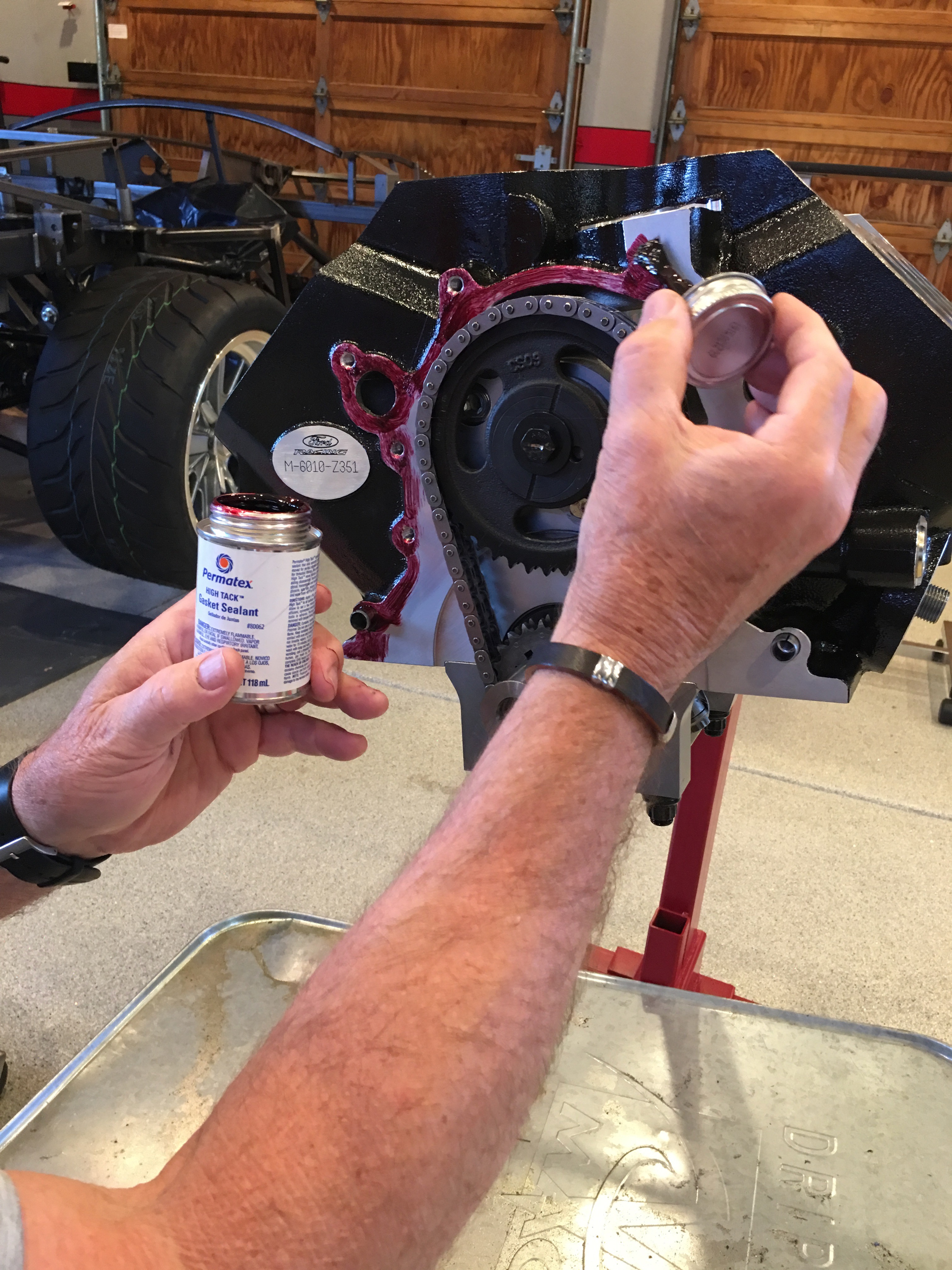
This stuff works like contact cement, so you have to let it tack up on both surfaces before sticking them together.

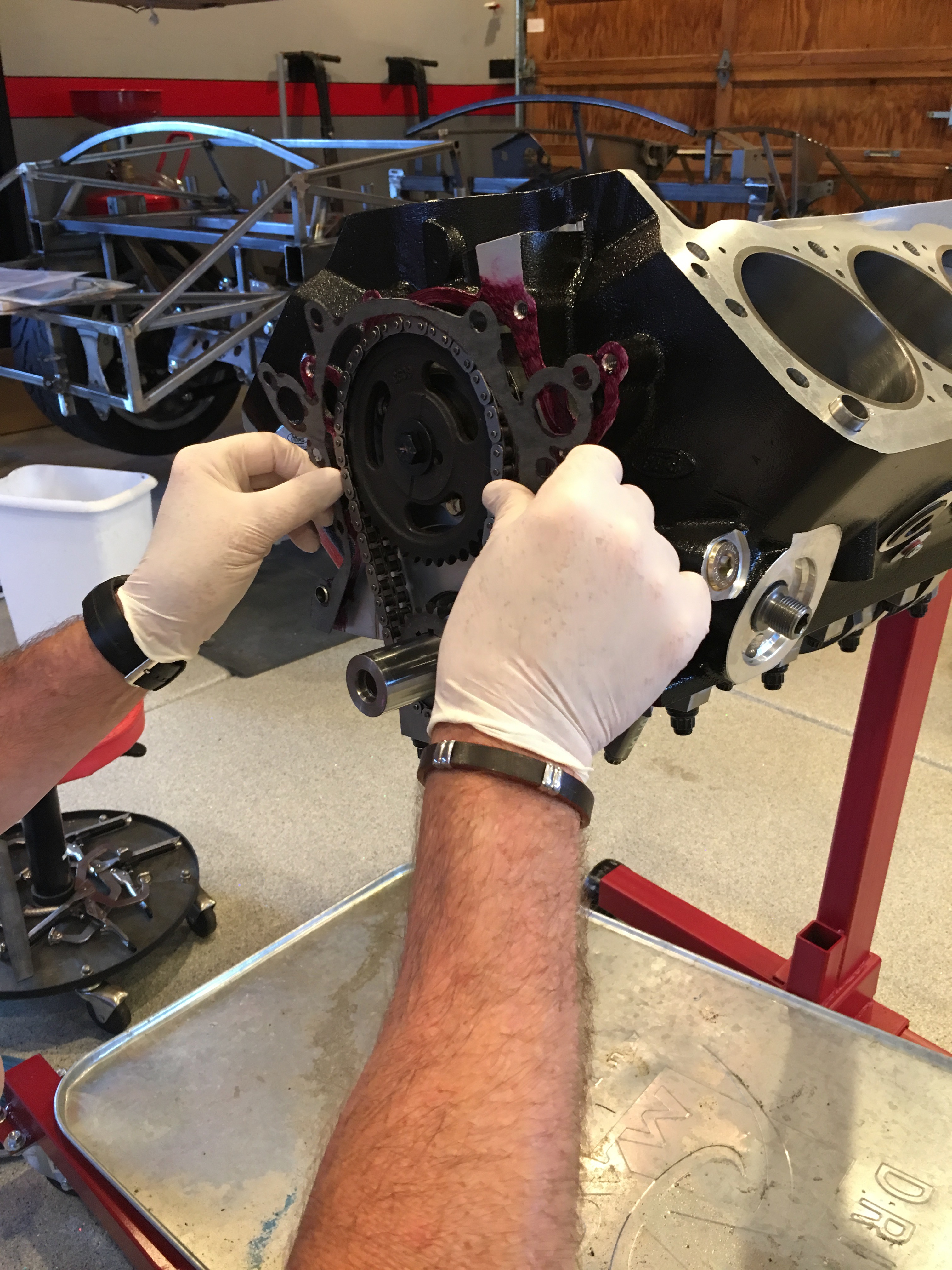
A second coat was then applied to the other side of the gasket and the mating surface on the timing chain cover.

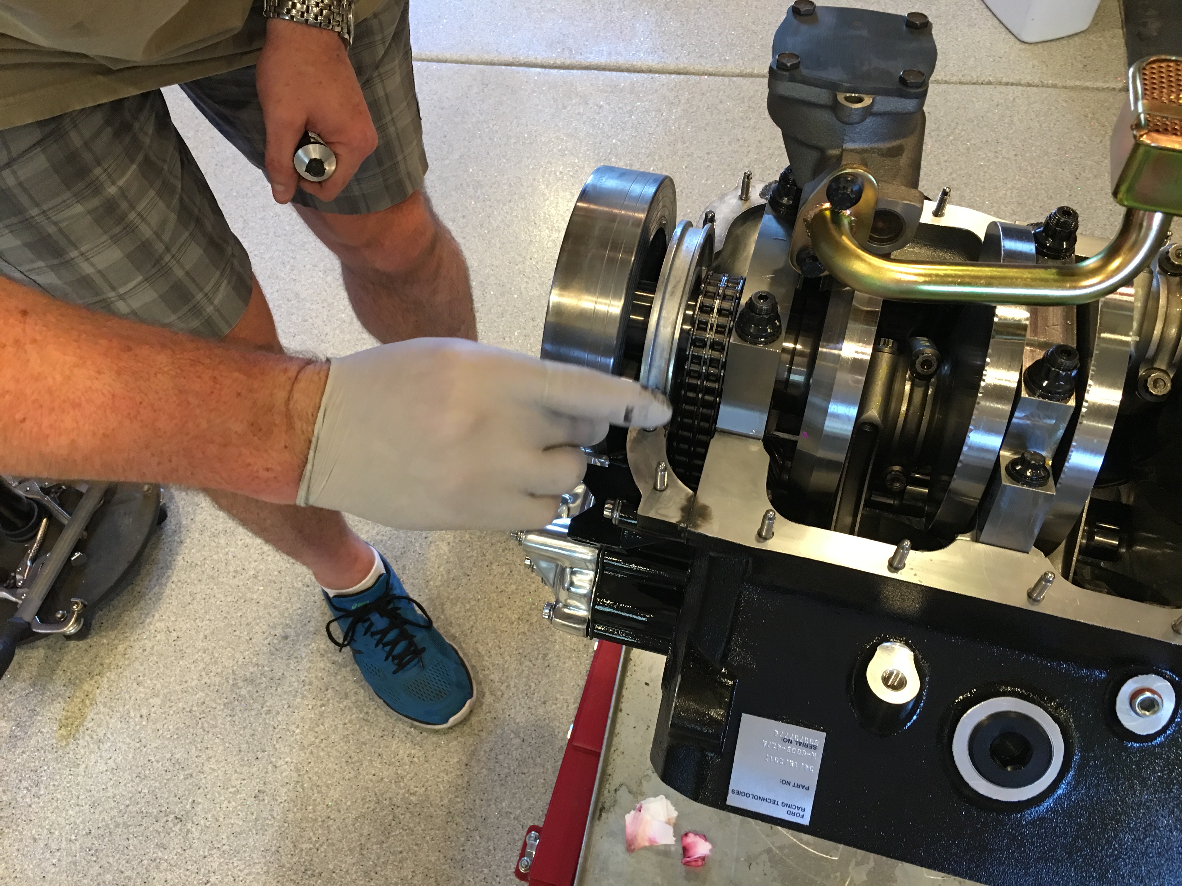
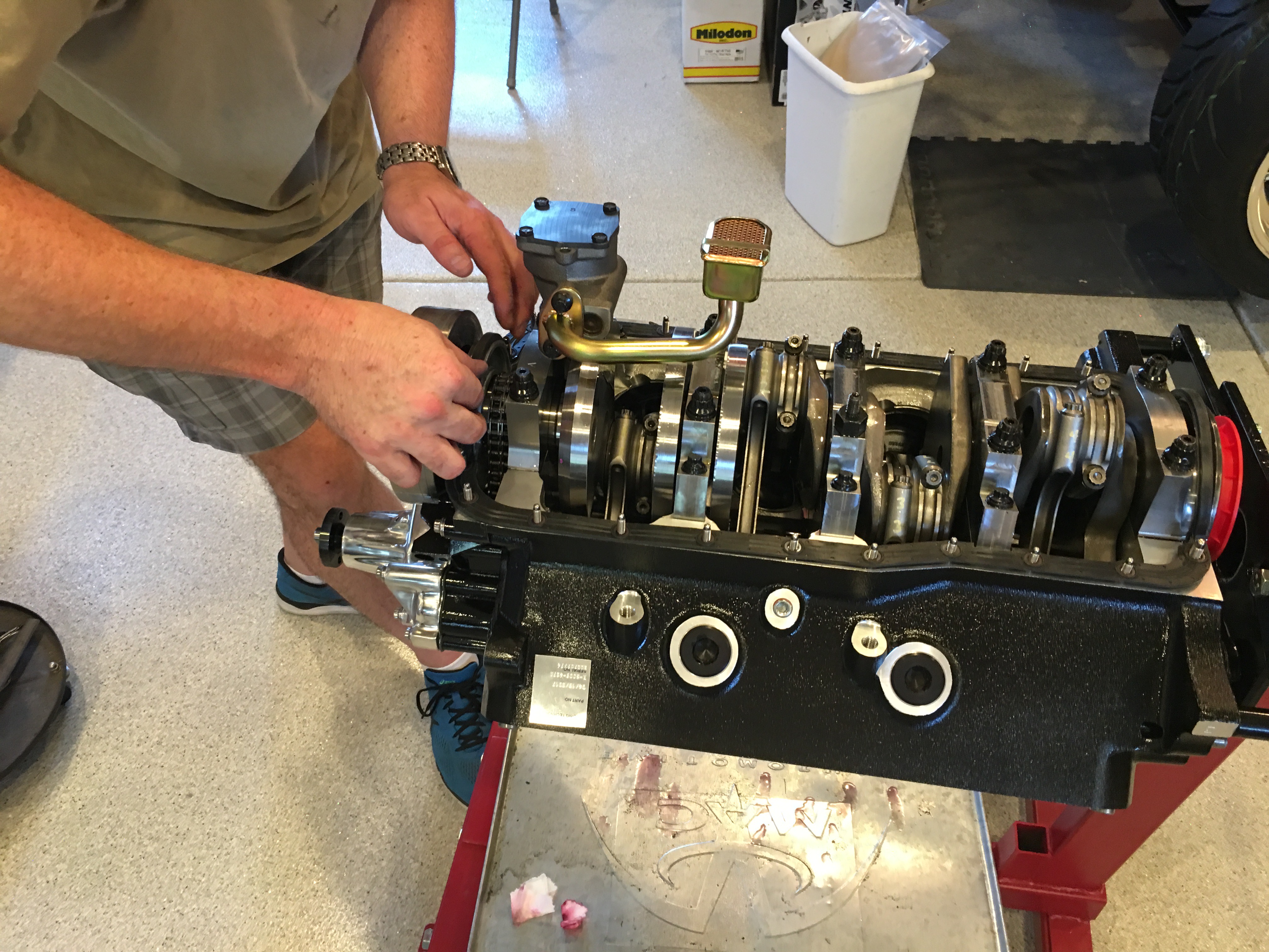
My dad and uncle installed the timing chain cover and water pump on the engine and held it in place until I could get a couple of bolts installed.

Jenn installed the remaining bolts…

… and then torqued them in three steps up to final torque.

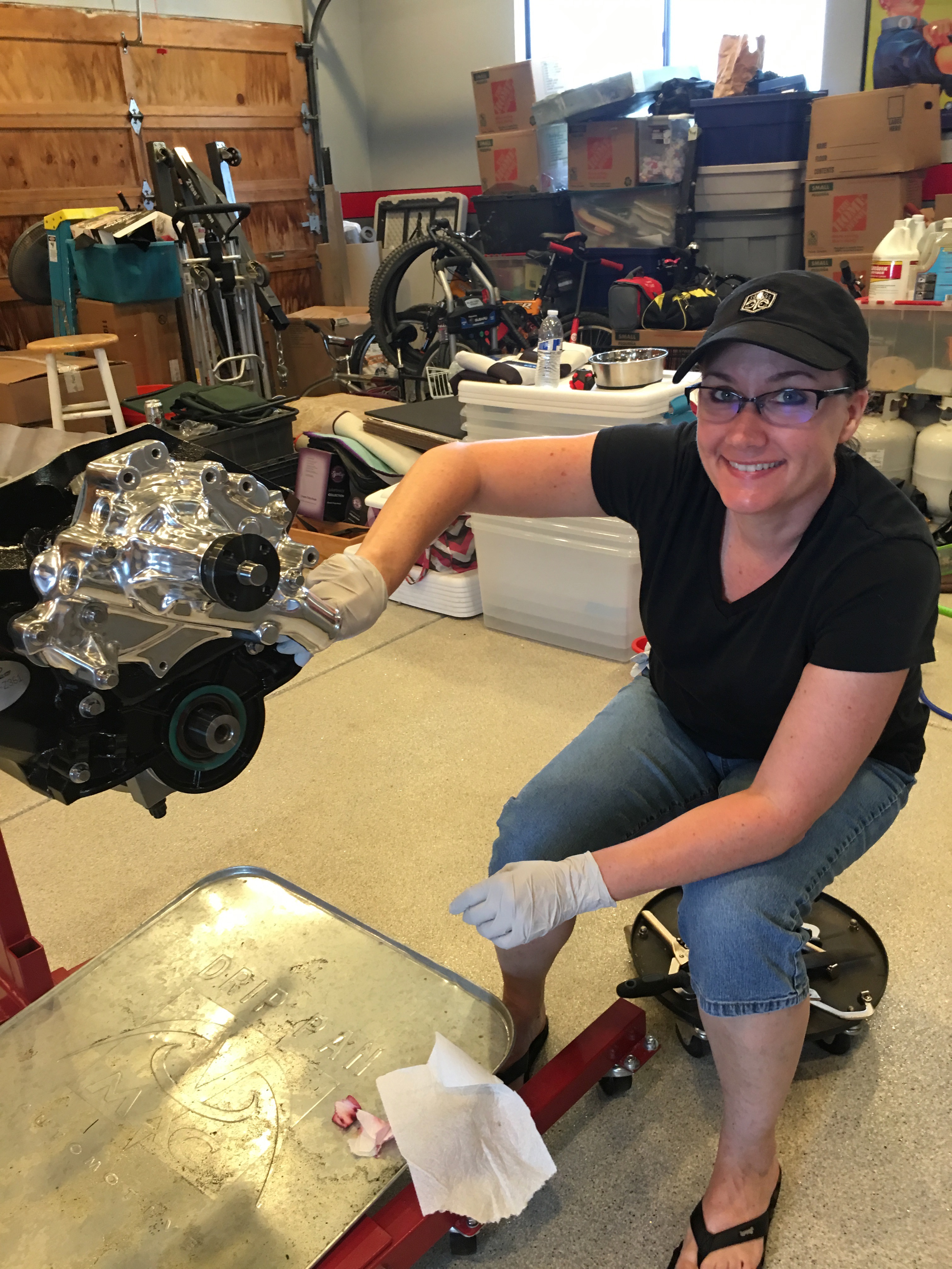
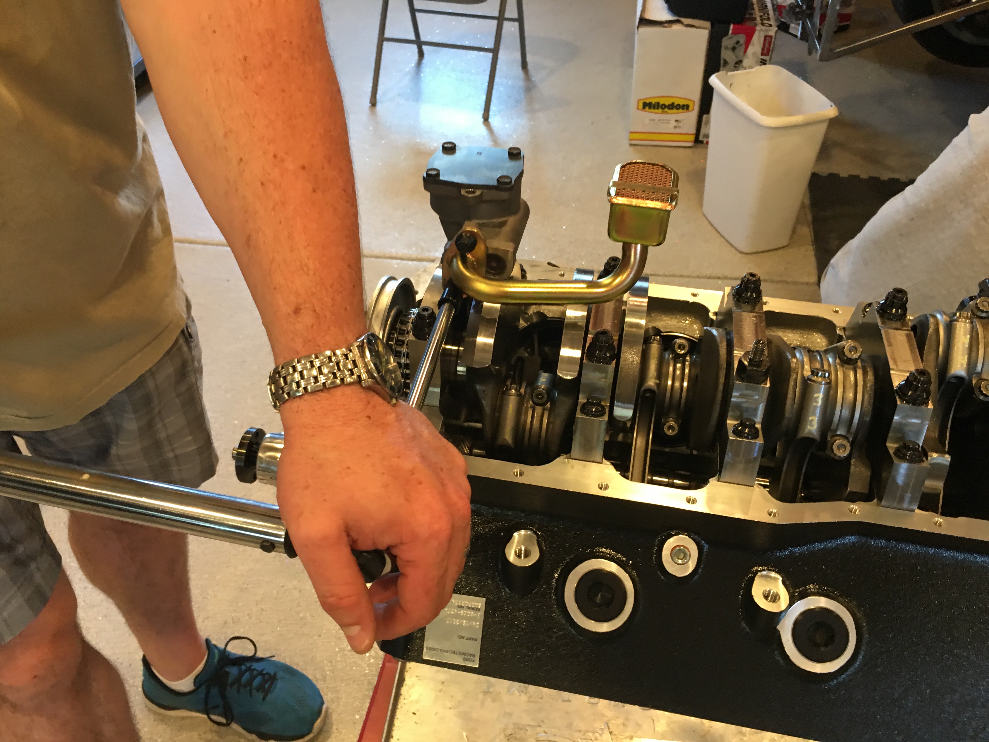
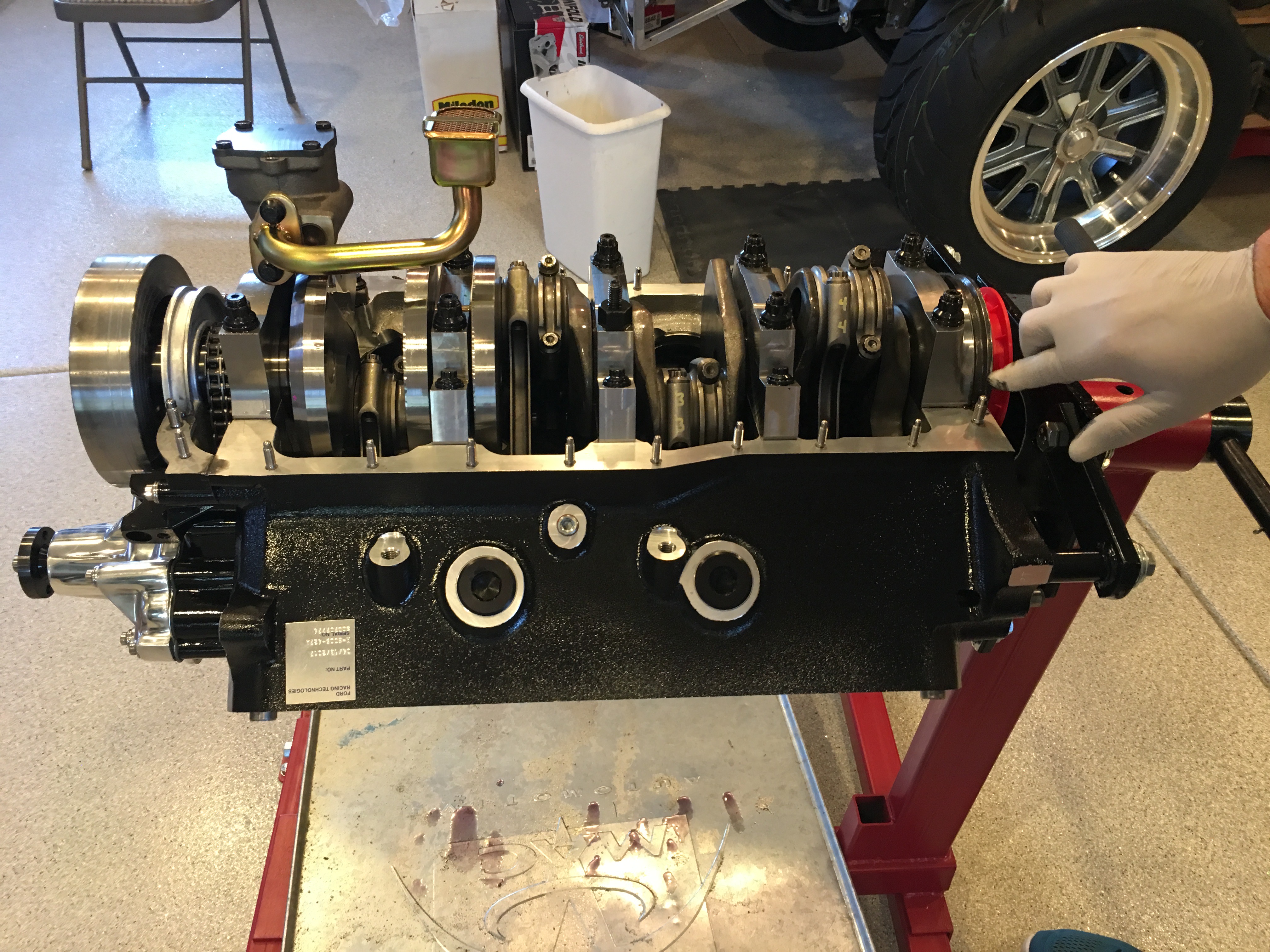
We then flipped the engine and installed the oil pump and pickup.

Before installing the oil pan seal, I applied a thin film of RTV over the end seals.

I also installed a small blob of RTV at the intersection between the arch and flat section. I also put a thin layer at the joint between the timing chain cover and the block.

We then dropped the oil pan seal in place. I applied a thin film of RTV along the sides of the arches to act as a lubricant to allow the oil pan to slide into place without distorting the seals.

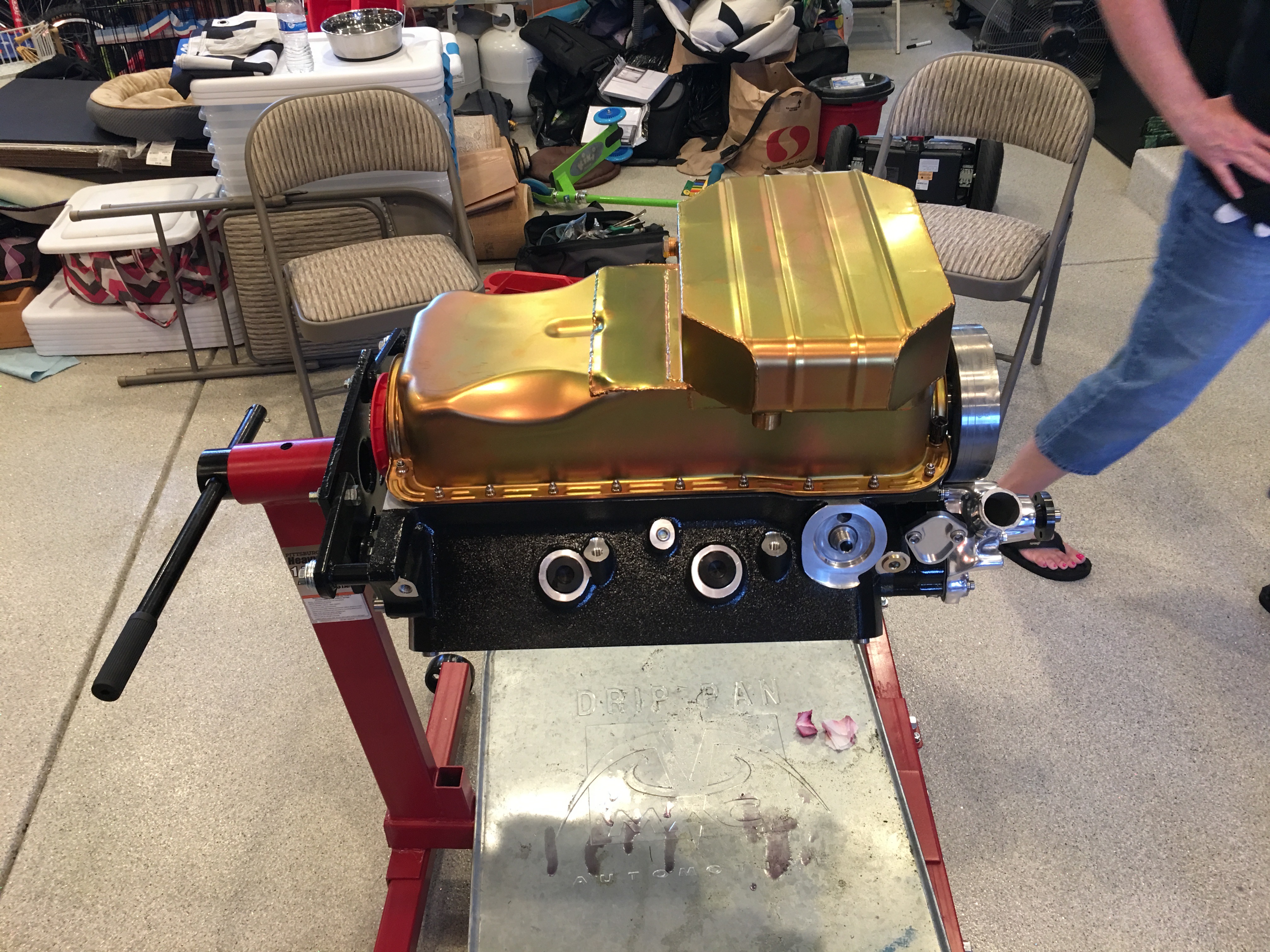
We then installed the oil pan and torqued the bolts to spec.

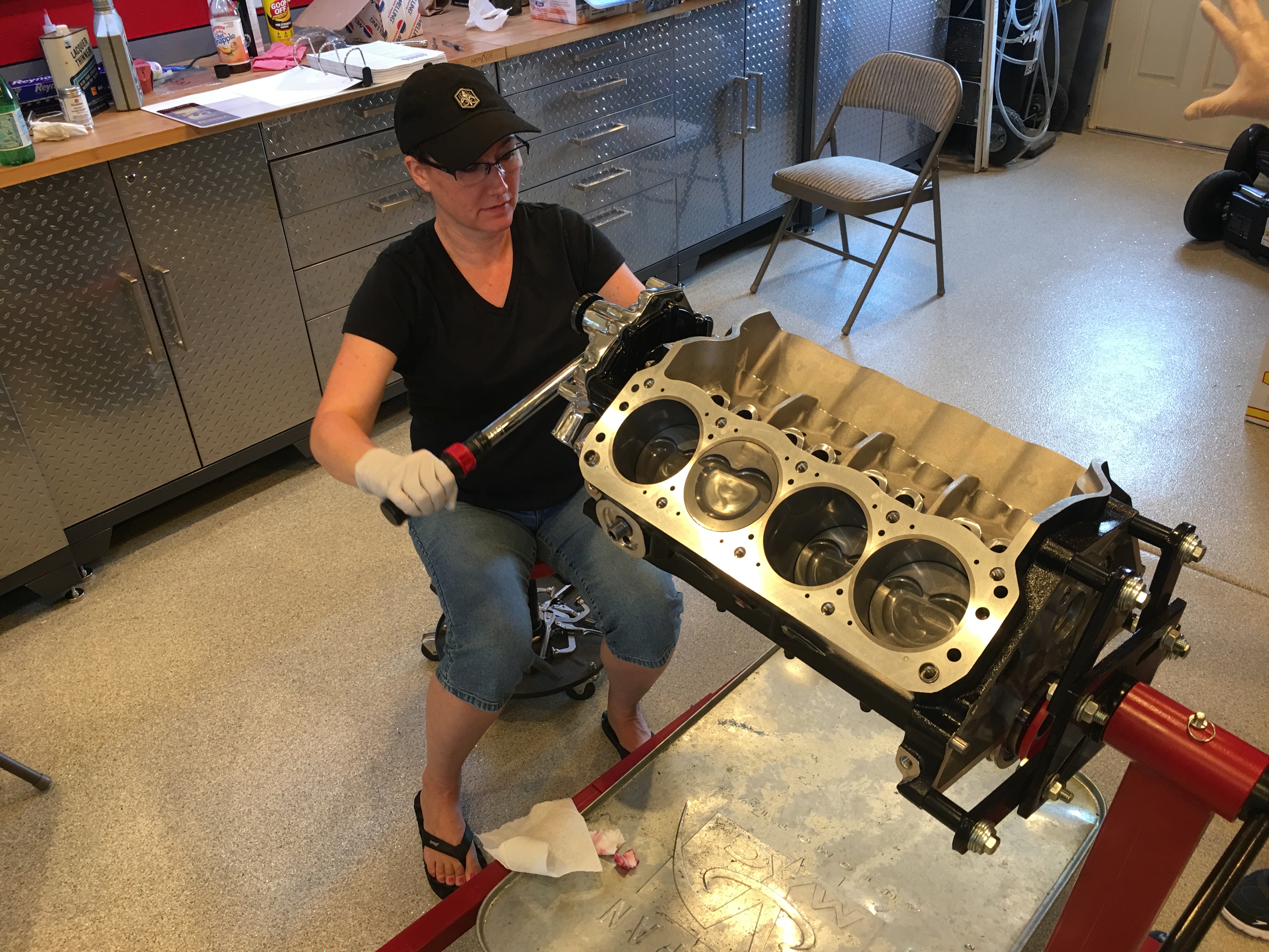
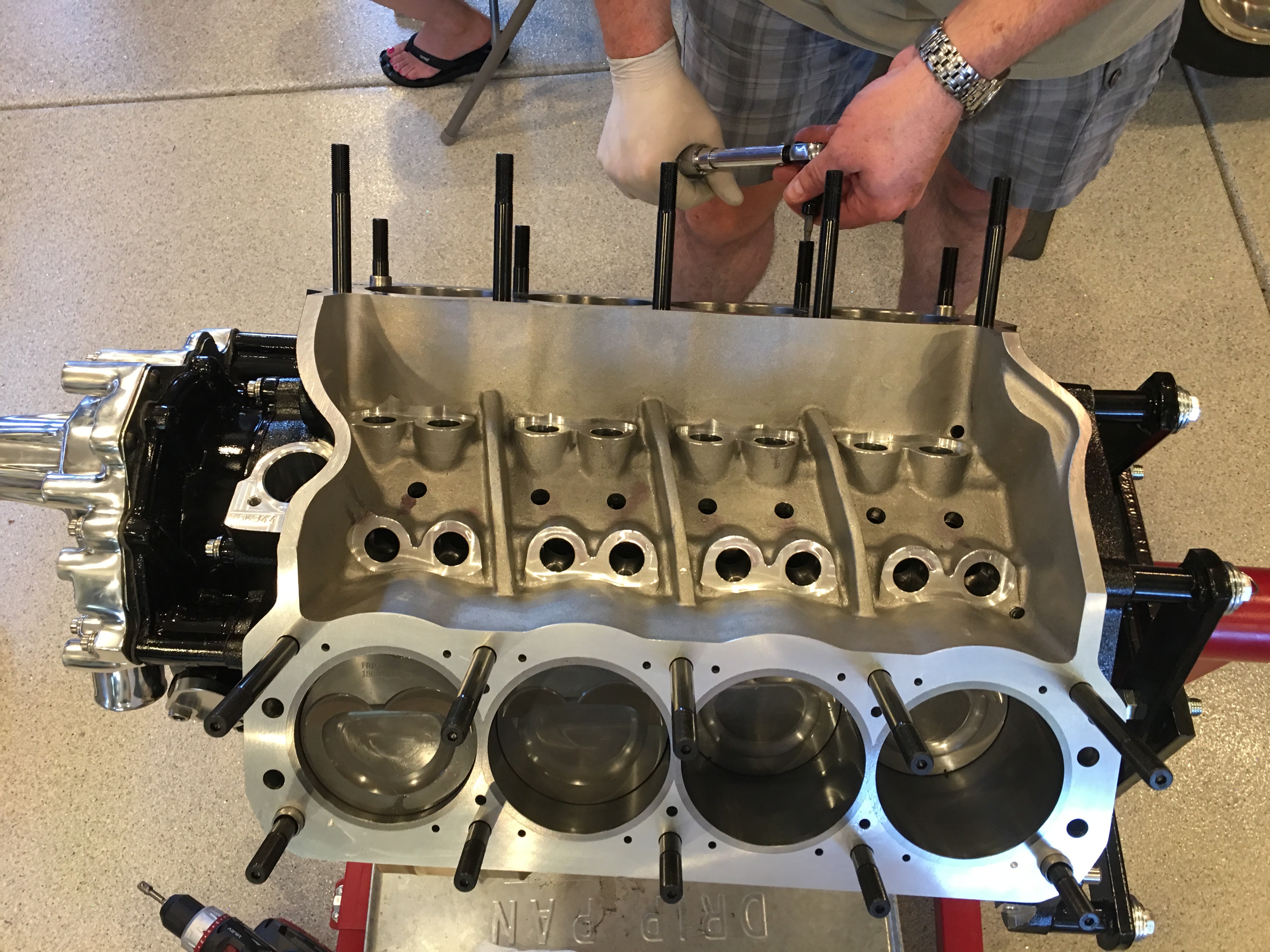
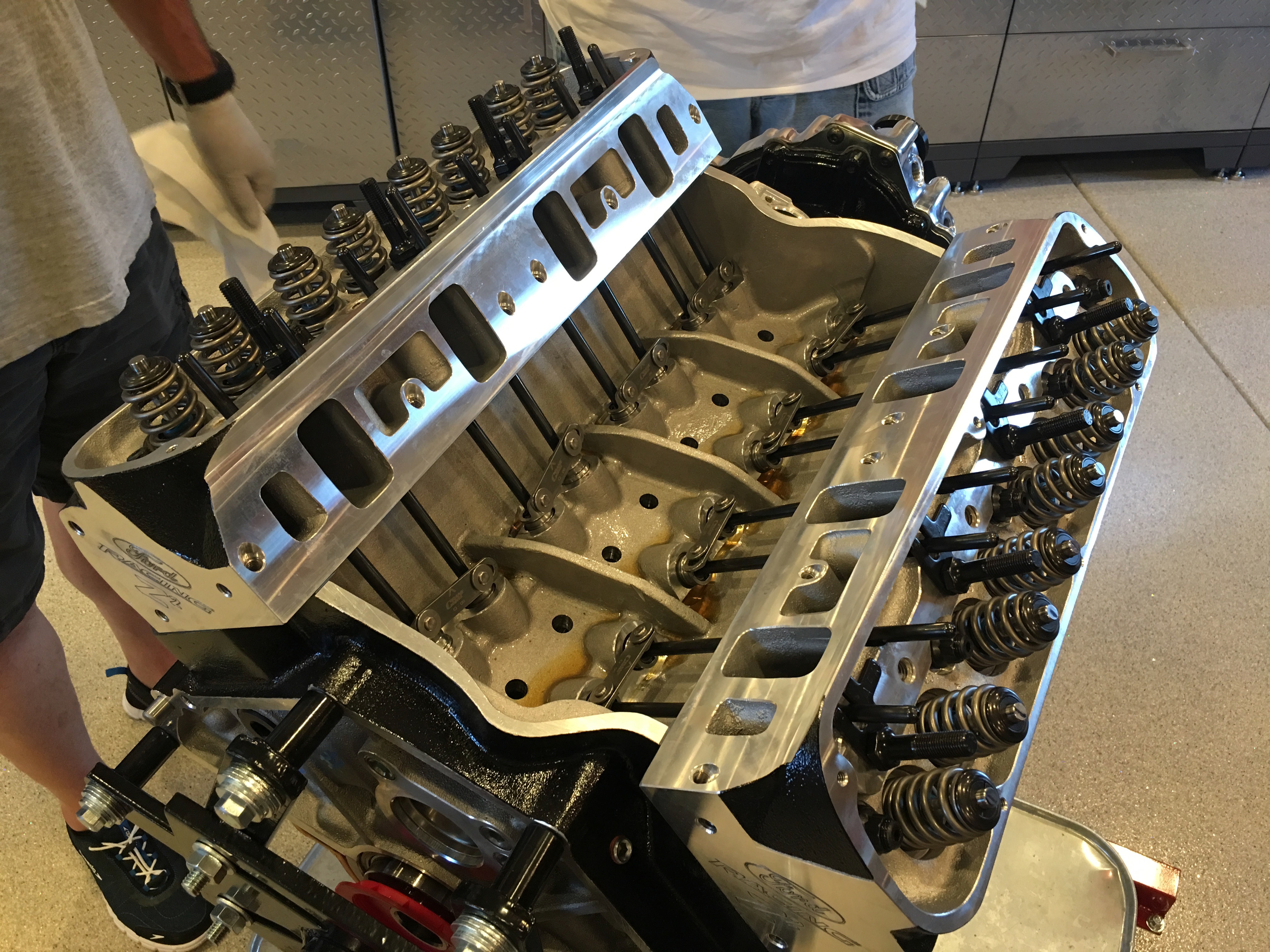
With the bottom end of the engine done, we flipped the engine over and installed the head studs. These get lightly torqued into the block (about 3-5 ft-lb). Jenn also dumped 7qts of oil into the lifter valley where it will drain down into the pan.

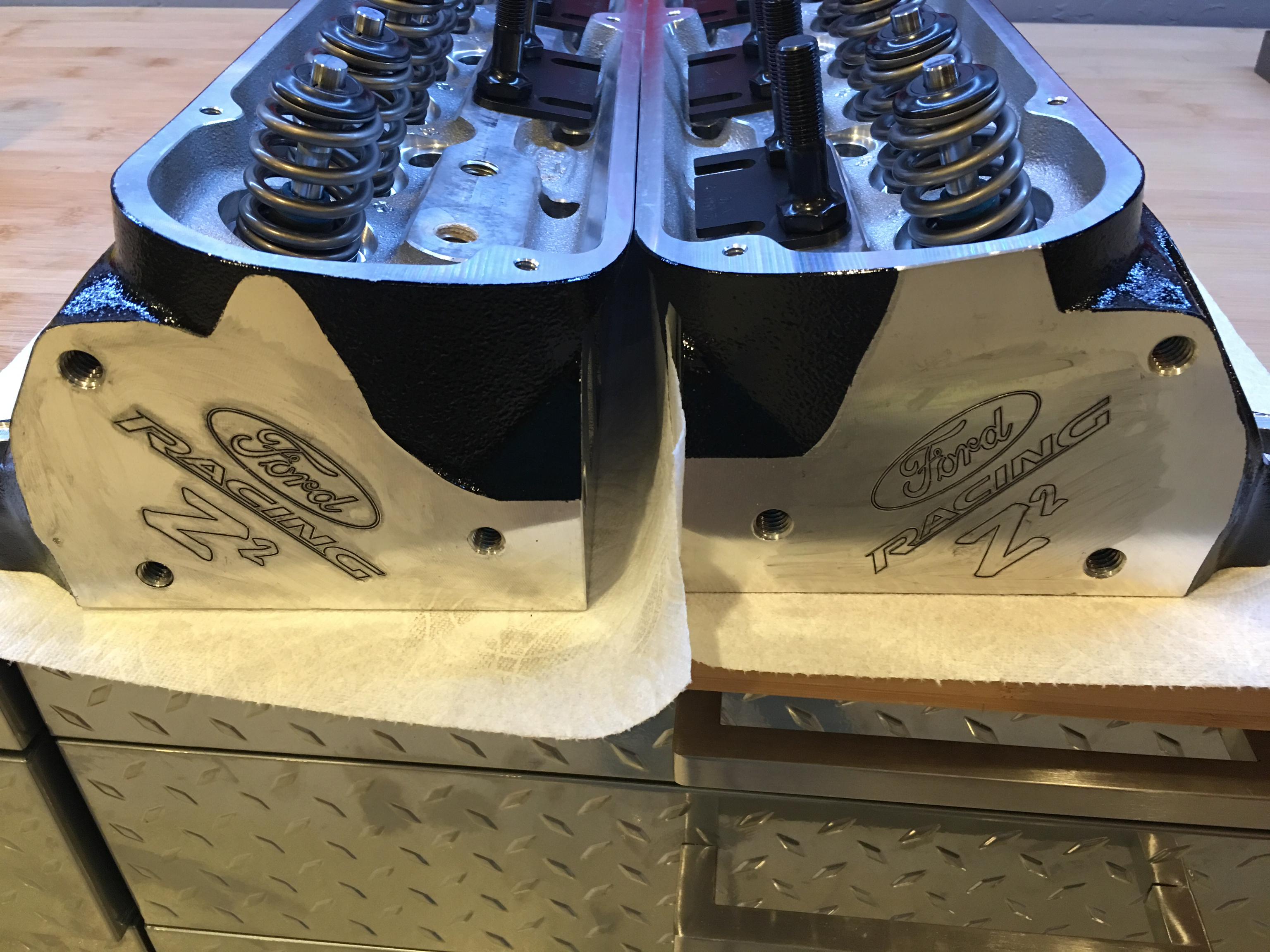
We then dropped the head gaskets into place. I had previously trimmed these to exactly follow the edge of the heads so that they don’t hang out.

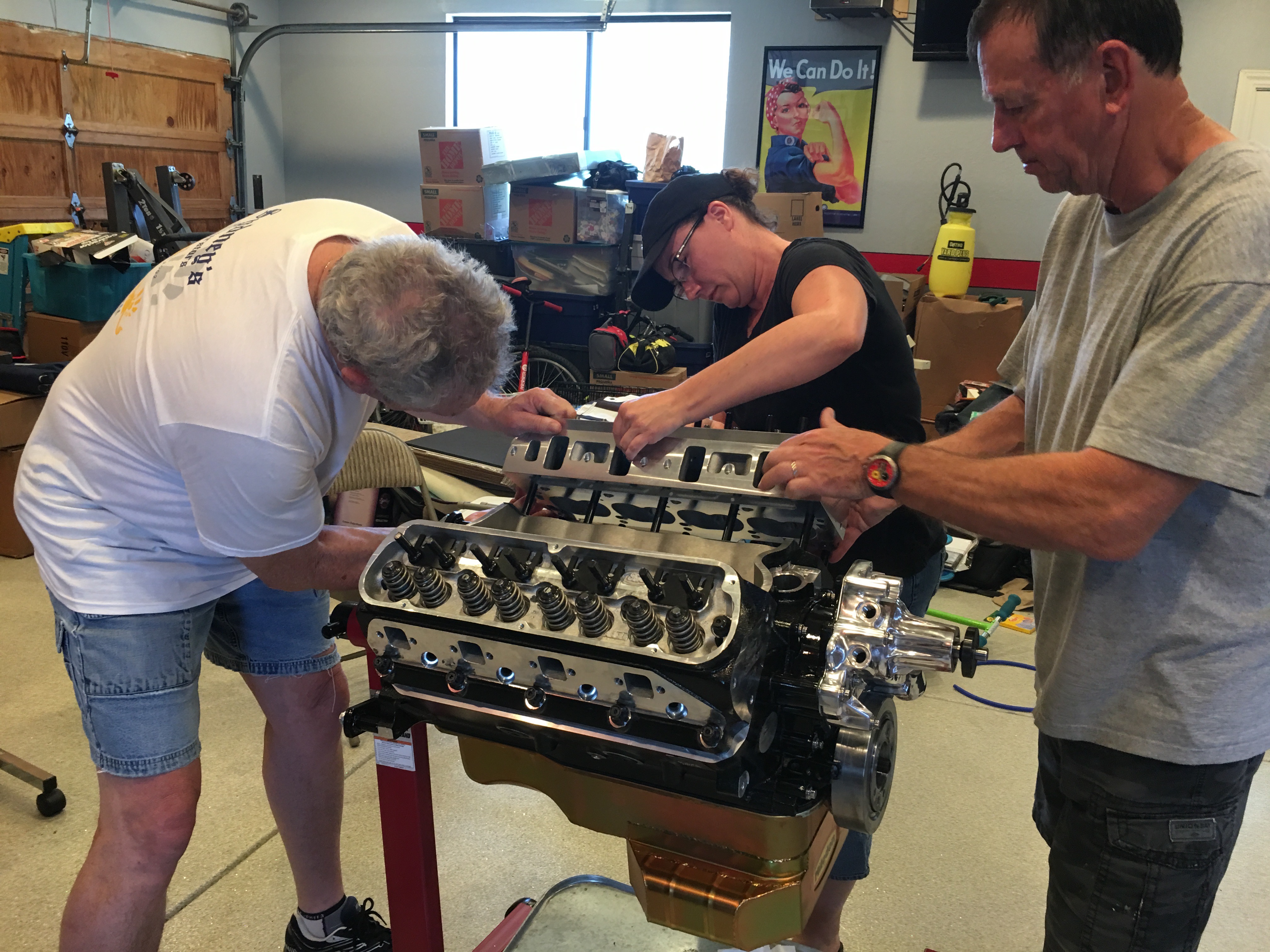
With help from my dad and uncle, I installed the first head and Jenn installed the second.

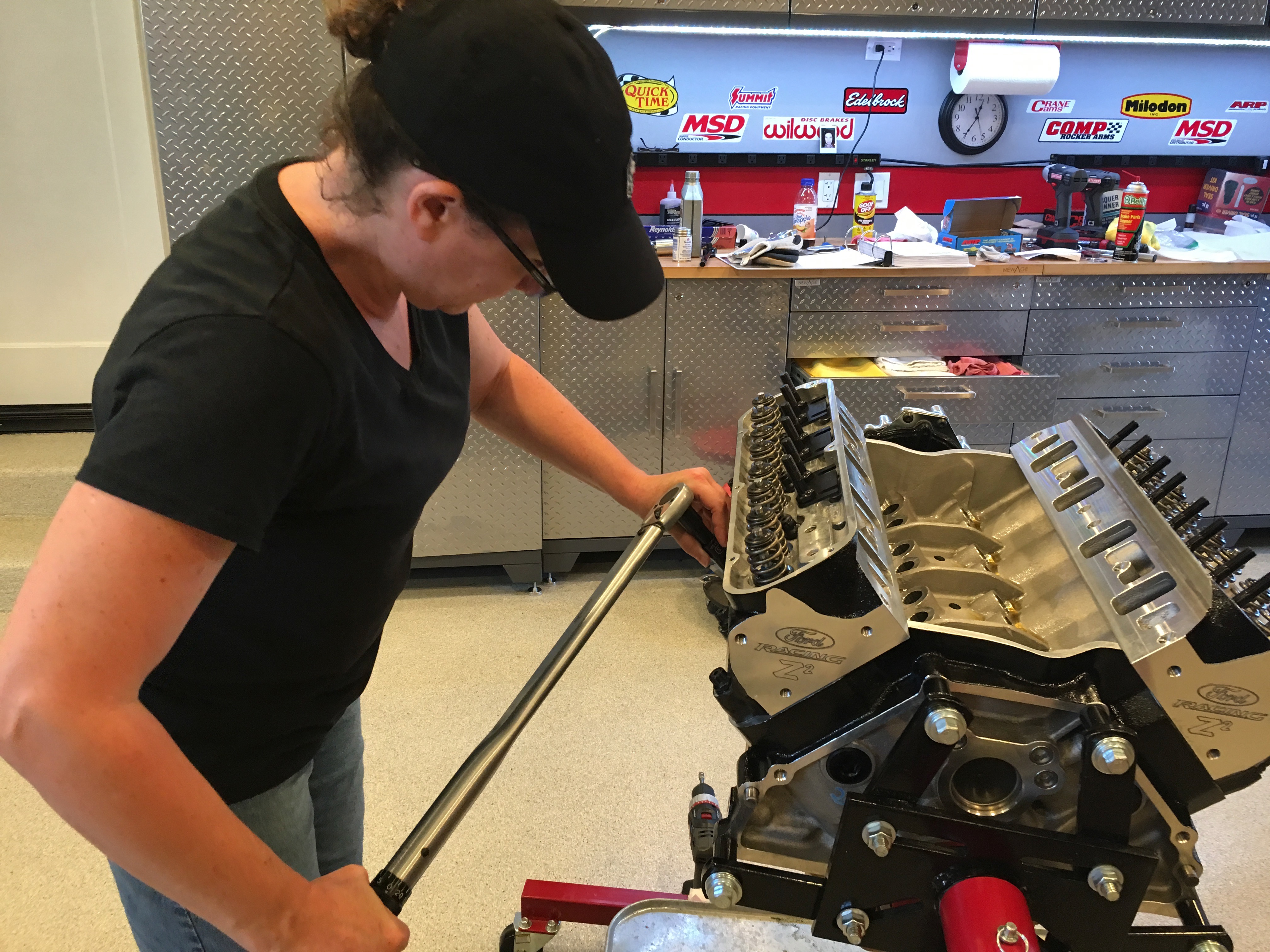
We took turns torquing the head bolts in three steps up to final torque.

My uncle dropped in the lifters…

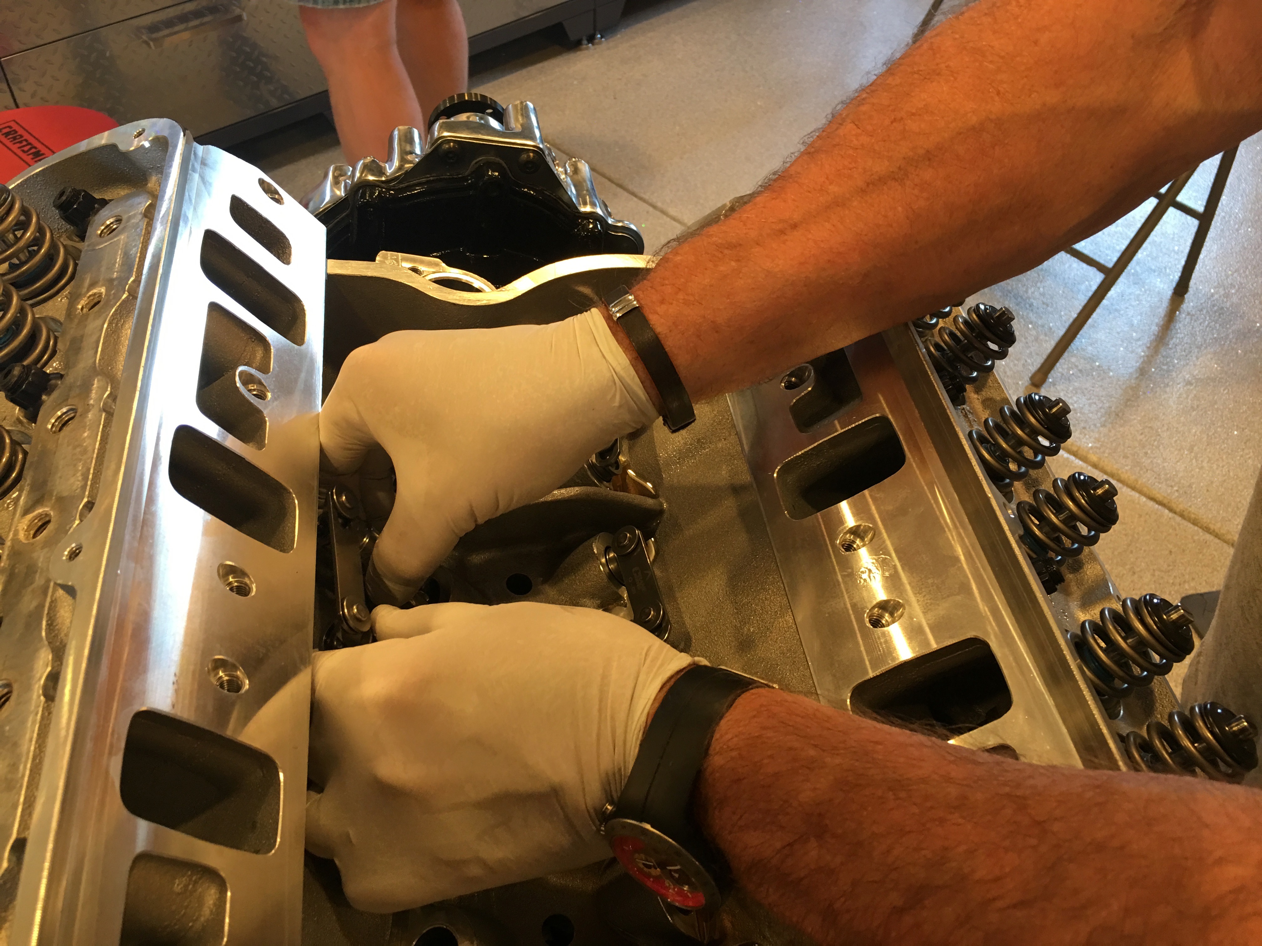
… and I dropped in the pushrods.

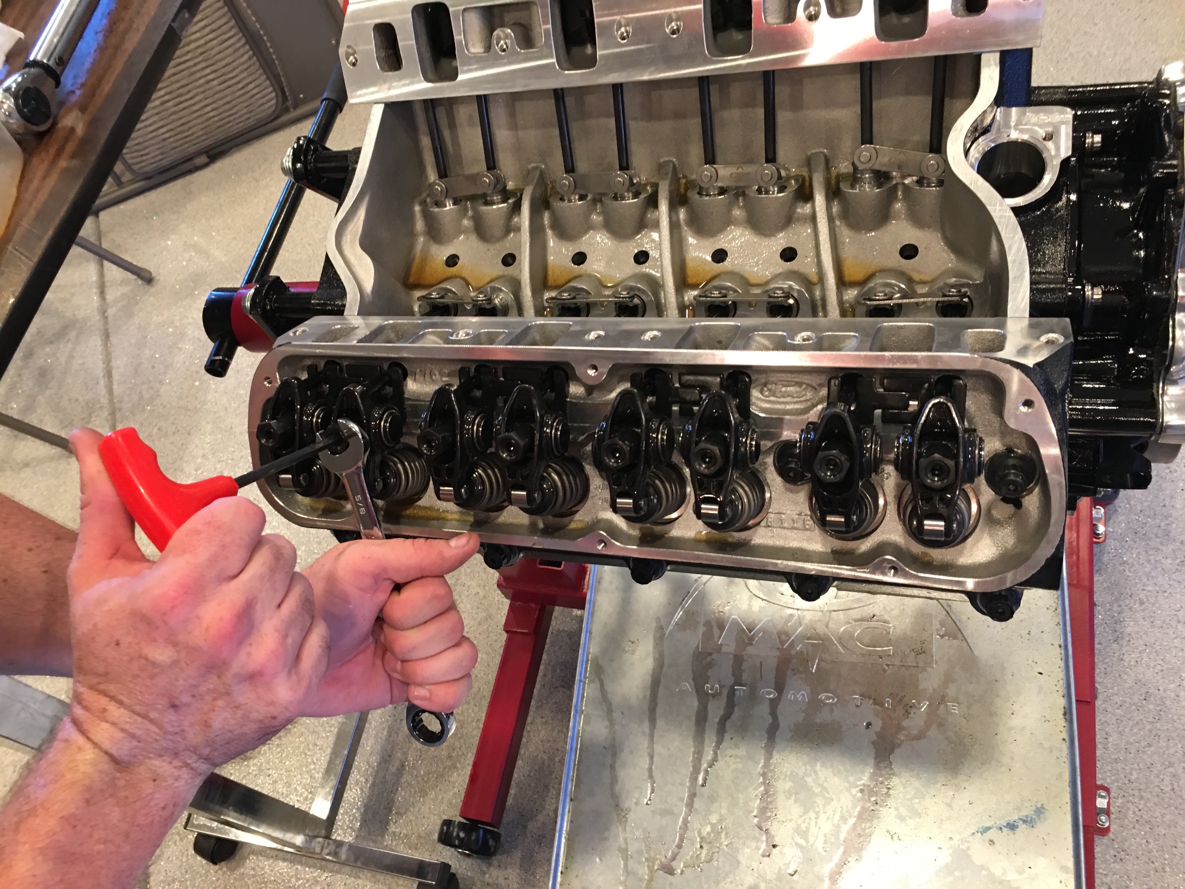
We pulled all of the rocker studs to install the adjustable guide plates. After visually lining up the pushrod, rocker stud and valve stem, we torqued the rocker studs back to 65 ft-lb. All of the intake studs need to be installed with thread sealant since they go into the intake port.

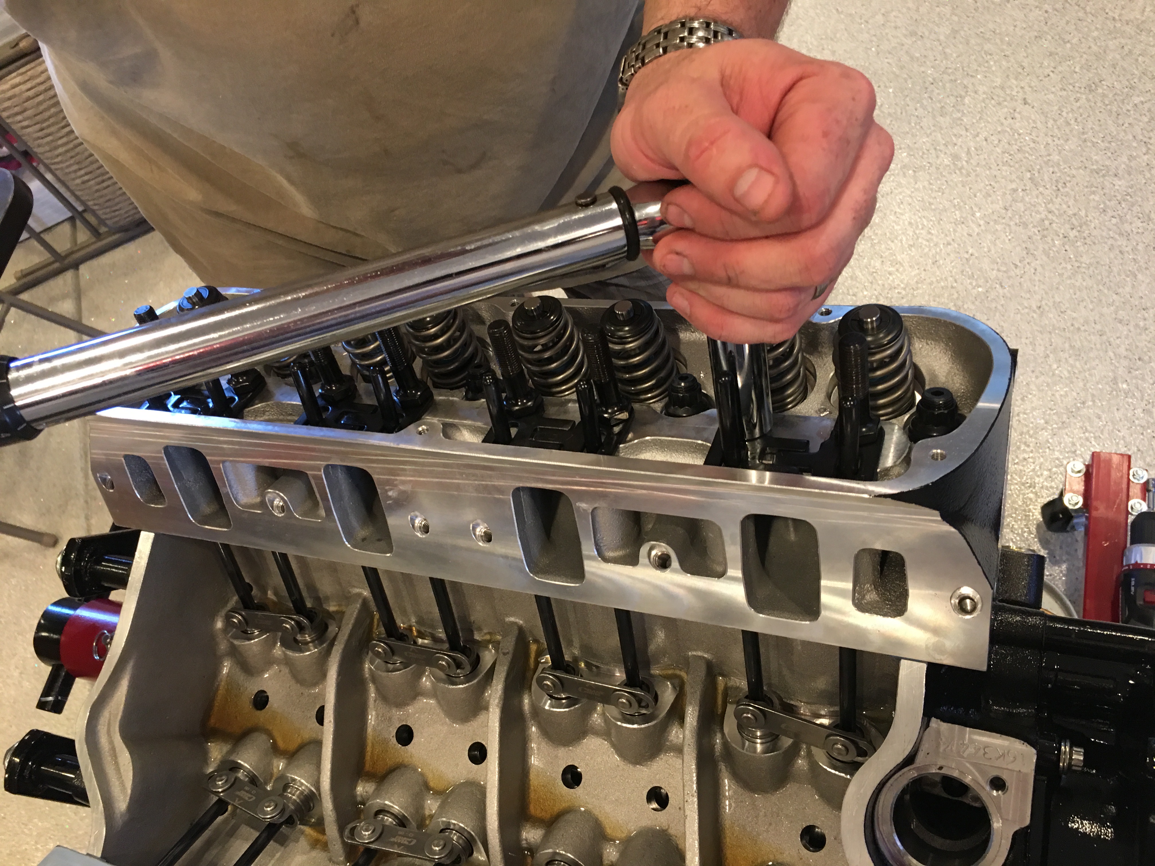
The visual approach lined up most of the rockers, but we had to pull a few and adjust the guide plates. After ensuring everything was lined up, we put 0.075″ of preload on the rockers and then tightened the set screws.

We didn’t get any pictures of the process of installing the intake manifold, but we installed RTV on both sides of the intake manifold gaskets around the water jacket and then some high-tack to hold the gasket in place. We then put a heavy bead of RTV on the end rails of the lifter valley and set the intake manifold in place. We then torqued the manifold to final torque.

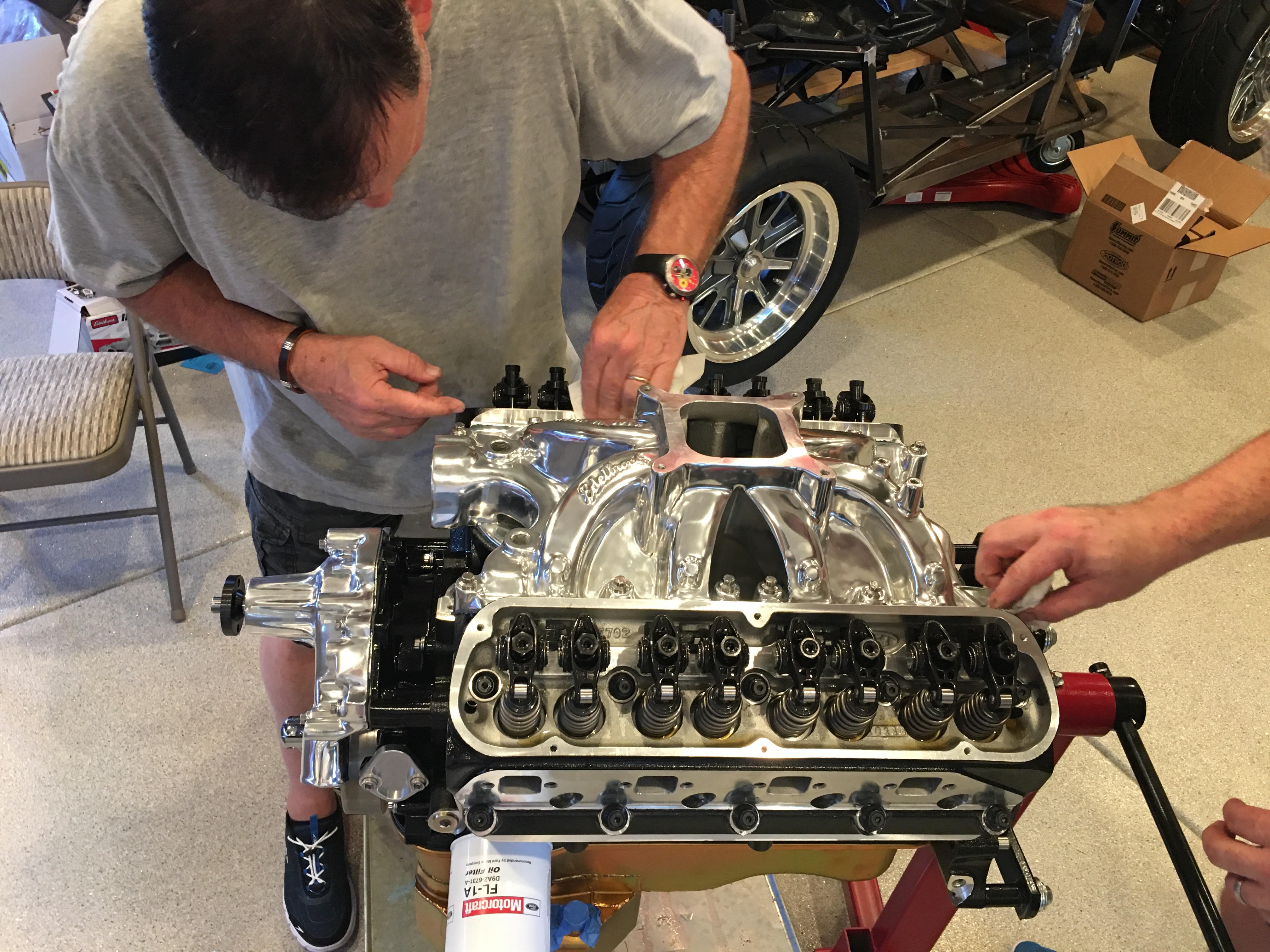
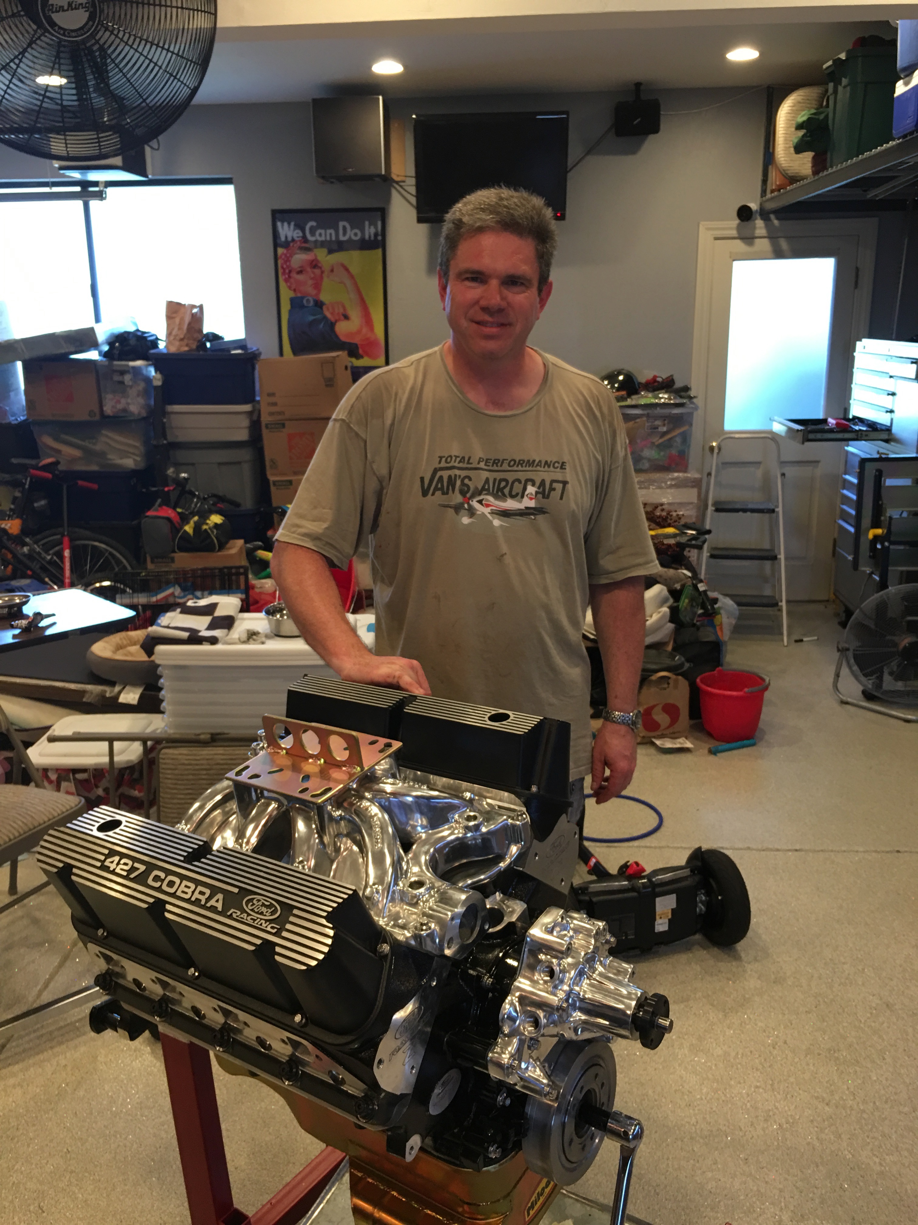
Finally, we installed the lifting plate to seal up the manifold and then installed the valve covers.

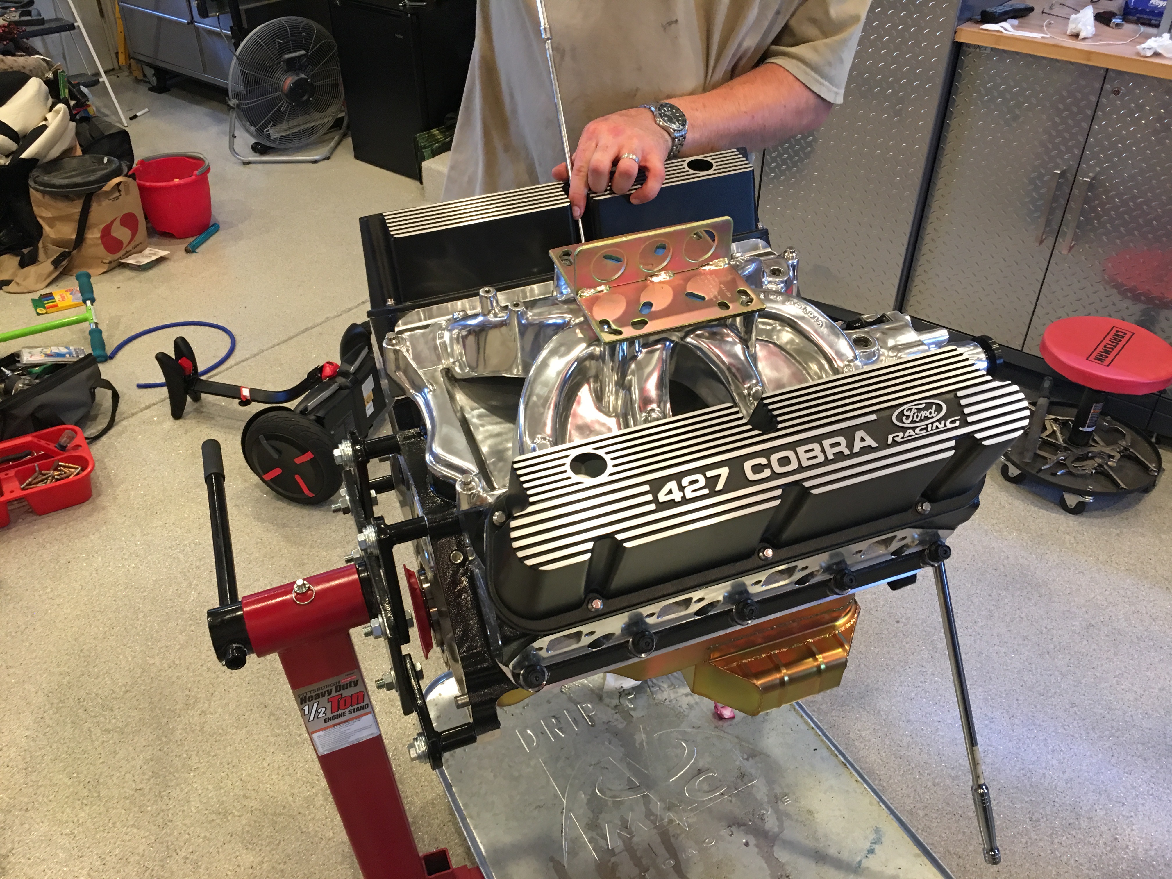
Here’s the result of our long day of work. After this picture was taken, I taped up all of the open holes to keep dust out of the engine.

Ordered Struts and Painted Cylinder Head Lettering

I talked to FFR this morning and they confirmed that I could use either the upper or lower strut mounting positions. They offer two because the single and double adjustable shocks they include in the kit aren’t the same length. With the chassis at ride height, I measured the resting length for the front and rear struts using both the upper and lower mounting positions. I also measured the strut and spindle mounting distances on the lower control arms to compute the motion ratio. This gives me all of the information I need to compute the correct strut length, but I still need to decide on spring rates. FFR recommends 500lbs in the front and 350lbs in the rear, but from what I can tell, part of the reason for such high rates is that the Koni struts they include in the kit have very little remaining travel at the normal ride height and the high spring rates help prevent the struts from bottoming out. The QA1 struts have a greater range of travel, so I shouldn’t need quite as high spring rates. After a bunch of research, we decided that we’d start with 400lbs in the front and 250lbs in the rear. I’m assuming we’ll end up ordering additional springs when we’re dialing in the suspension down the road.

I spoke with one of the engineers at QA1 and gave him the dimensions I measured and spring rates. He recommended the following items:

  • D4501 quad-adjustable shocks, front and back. These have a travel of 11.625” – 16.875”.
  • 10HT400 springs, front. These are 10″ long; 12″ long springs would work, but they would put the ride height adjustment nut at the very bottom.
  • 10HT250 springs, rear.

He also recommended using the lower mounting holes on the front and the upper on the back which only have a 1/8″ difference in resting length. These items are all on order, so I should be able to confirm they fit some time next week.

With the measurements complete, I put the chassis back on the dolly.

One last thing I’ve been wanted to do before engine assembly is to paint the engravings at the end of the cylinder heads. I tried this earlier and ended up wiping off the paint because it wasn’t looking great. I tried a new technique tonight which worked much better. I cleaned the engravings thoroughly and then used a q-tip to apply paint over the engravings thick enough that I couldn’t see them. I then let the paint set up for a couple of hours and then used some solvent to remove everything on the surface. You can still see a haze of paint around the engravings, but that should come off with some more solvent. I didn’t want to go further tonight though since it would be easy to go too far and have the solvent remove the paint from the engravings. I made sure I did opposite ends on the cylinder heads so that if this doesn’t turn out well, I can just put these at the back of the engine and no one will ever see them.

Installed Front Brakes and Filled Differential

I got started this morning on the front brakes which are a little more of a pain than the rears. The bracket that holds the caliper on doesn’t fit the FFR spindles without some modification. After searching the forums, the consensus is to grind the spindle until the bracket fits. The only interference is with the upper mounting hole on the bracket, but that part of the spindle is super thick. I only needed to remove about 1/16″ of material, so strength is not compromised.

With the Big Brake kit from Levy Racing, there is very little clearance between the wheel and the caliper, so the caliper needs to be biased inboard a bit. The instructions from Gordon are to shim the caliper inboard enough that the outboard pad can just barely be inserted. I ended up using about 0.150″ thick shim to space the mounting bracket inboard which lets me insert the the outboard pad with about 0.012″ of clearance. Even though the gap is greater on the inboard side, this will even out the first time the brakes are applied. Since there are pistons on both sides, the inboard pistons will just extend a little more.

Wheel spacers are used to shim the wheels outboard about 0.090″, but that still only leaves about 0.040″ between the back of the spokes and the face of the caliper.  Since the calipers are rigidly mounted and don’t float like most OEM calipers, this is more than sufficient clearance.

The reason I wanted to get the wheels on now is that I need to measure for the struts. The manual says the chassis ride height should be 4.5″ from the ground to the bottom of the 4″ main tubes. I laid down three 2x4s and then set the chassis down on them.

I did the same thing in the front and then adjusted all four control arms to put the wheels at zero camber.

I put a couple of bolts in the upper and lower mounting brackets and measured for the ride height distance. It’s a little unclear whether the upper end of the shocks should bolt into the upper or lower hole.

I drained the differential in preparation for filling it with new fluid.

I was pleasantly surprised to see that both the fill and drain plugs both included magnets to catch any loose metallic particles floating around in the oil.

My dad brought over this contraption he made to fill transmissions and differentials. It hooks up to a compressed air source and then has a needle valve to control the air pressure in the canister. There is a pickup in the bottom of the canister that connects through a fitting to the tubing on the top. When pressurized, fluid is forced up the tube. The plastic canister can’t take much pressure, so it takes awhile to pump 2.5L of fluid up into the diff.

Installed Rear Brakes

My dad stopped by today and we worked on the rear brakes. I’m still missing the right caliper, so we got started on the left side. The bracket bolted on without any issue and the main caliper and parking brake caliper bolted up to the bracket easily. I needed to shim the bracket over slightly to center the caliper and I may still need to shim the caliper away from the axle slightly, but this is good enough to measure wheel clearance.

We wrapped up the other side (minus the caliper) and installed the rear wheels. We have about an 1/8″ gap at the closest point between the parking brake caliper and the wheel, so we’re good on clearance.

Flipped Control Arm Fittings

I was reading back through the instructions to double check our work and noticed that they say to make sure the grease fittings are facing up on the upper control arms. I didn’t double check this earlier because the upper ball joint really defines the orientation of these control arms. Looking more closely at the photos though, it was clear that the upper fittings were installed upside down on the control arms we received. I removed the bolts and flipped the upper fittings. This changes the geometry slightly, but it will definitely make it easier to access the grease fittings for future maintenance.

Front Spindles and IRS

Jenn got started this afternoon installing the hubs on the front spindles. These only required some light tapping to get them on far enough for the nut to be engaged. Tightening the nut allow the hub to be pulled on the rest of the way.

Jenn’s excited to finally get started on the car after a brutal work schedule over the past six months.

The kids wanted to help, so we had them tighten the axle nuts until they were too tight for them to turn.

Now that Madeline’s an expert, she can supervise Matthew as he tightens the other axle nut. After the kids took them as far as they could, I torqued them to spec.

After wrapping up the front hubs, we moved on to installing the differential. Jenn’s tapping the bushings into the front mounting holes.

Getting the diff in place wasn’t too painful. We stood it on end and used the floor jack to lift it most of the way into position. I then pivoted the diff horizontal while Jenn started the rear bolts.

After installing the front bolts, Jenn torqued everything to spec.

We assembled the toe arms and bolted them in place.

We then bolted in the lower control arms and torqued them to spec.

After inserting the half shafts, we bolted in the upper control arms.

We slipped the rear hubs over the end of the axle and used the axle nut to pull the hub part way onto the shaft. We then aligned the three mounting ears with the various control arms and bolted it in place. We then torqued the axle nut and mounting bolts to spec.

The entire IRS it installed; it looks pretty damn sweet!

Started Work on Suspension

Jenn and I started work on the suspension this morning. First up is to mount the F panels. These are the Fat Tire F Panels from ffmetal.com. They let you run wider front tires (up to 275 or so) without rubbing when the wheel is turned to the stop. These are basically slid up until the lower bend is at the corner of the lower steel tube and the slid forward until the forward upper end is at the apex of the bend, then clamped in place.

That positions the panel a little bit above the upper support, so we marked and trimmed it to fit.

After laying out the holes on the F panel using a rivet fan, Jenn match drilled it to the chassis.

Since we’re going to be completely disassembling the chassis for finishing, we’re going to hold all aluminum panels on with screws until then.

Afterward, we bolted the upper and lower control arms in place and then attached the spindles.

Jenn had a dinner planned with her friends, so I used that opportunity to run down to the TechShop and modify the rear knuckles. After roughly cutting off the extra ears on the band saw, I mounted them to the bed of one of the milling machines and used an end mill to clean up the cut.

Finally, I used their large disc sander to radius the corner and the scotchbrite wheel to smooth everything out.

I then mounted the hubs to the knuckles. These are ready to mount on the car.