Welded New Chassis Tube

I clamped a piece of 3/4″ tubing to the outside of the forward tube and welded it in place. It was then fairly easy to flex the two pieces of tubing into alignment and weld the rear pieces together. I’ll finish going all the way around the weld and clean it up with a grinder when the car comes back apart.

Taillight Wiring and Clutch Pedal Clearance

I installed Weather Pack connectors on several of the tail lights. I ran out of three-conductor connectors though, so I couldn’t finish all of them.

I also installed the female connectors on the chassis on both sides. These are electrically identical and all lights have identical connectors. This is possible because the InfinityBox lets you use the same lights for brakes and turn signals. Although this is possible with a combination of relays in a traditional wiring harness, most builders don’t wire it this way. They end up using the dim filaments in all four tail lights for their parking lights, but the bright filaments in one pair of lights for the brakes and in the other pair of lights for the turn signals. In our car, all four bright filaments will be used for brakes and turn signals.

When I moved the pedal box up, it caused interference with the 3/4″ tubing that cuts through the middle part of the driver footbox. There must have been some stress in this tubing because the two pieces shifted out of alignment with each other when cut apart. I’ll weld in a new piece of 3/4″ tubing on the outside of this tubing. I’ll try and realign the pieces of tubing when welding.

It took a few extra trims on the forward end of the tubing to allow the pedal to go all the way to the front of the footbox, but I now have full clutch travel.

Finished Driver Side Floor Pan and Radiator Plumbing

I cut a couple of 2.5″ pieces of 1/2″ steel tubing. I’m going to weld them in a little proud of the upper and lower surfaces and then grind them flat.

I used a couple of welding magnets to hold the tubes in position.

After an ugly weld job, I ground the tubes flat and cleaned up the hole. I also did the same thing on the underside of the floor.

I reinstalled the seat pan and drilled the left side to the transmission tunnel.

I picked up some silicone couplers from HPS Performance Silicone Hoses. I removed the upper radiator tube and swapped in the silicone couplers.

These are much nicer than the cheap rubber hoses that came with the radiator tubes and shouldn’t suffer from cracking as they age like the rubber hoses.

The hose connection under the radiator cap on the water neck will connect to the hose fitting on the bottom of the coolant reservoir. I’m using the same silicone tubing that I used for the PCV valve and breather connections. I’m using one of the decorative ends which covers a standard hose clamp, but I had to trim part of it because of hose close the radiator comes to the hose fitting.

I need to route the hose along the top of the upper radiator tube and then down the x-frame and up to the reservoir. I haven’t figured out exactly how I’m going to secure this yet.

Strut Hoses and Trunk Aluminum

The parking brake cable rubbed against the strut reservoir hose, so I used a zip-tie and a short piece of plastic hose (extra from the brake bias adjustment cable housing) to tie them together while keeping them separated.

The hoses connecting the front struts to the reservoirs have a hose that is too long for our application. I had the hoses just making a gentle bend between the two and it went so high that it interfered with the upper control arm. I removed both reservoirs and put an extra bend in the hose. This places the hose completely clear of both the upper and lower control arms and should easily handle the flexing during suspension travel.

I realized that there were a couple of extra pieces of trunk aluminum that I never drilled to the chassis, so I took care of that before heading to bed.

Wrapped up Parking Brakes, Reinforced Chassis and Adjusted Brake Pedals

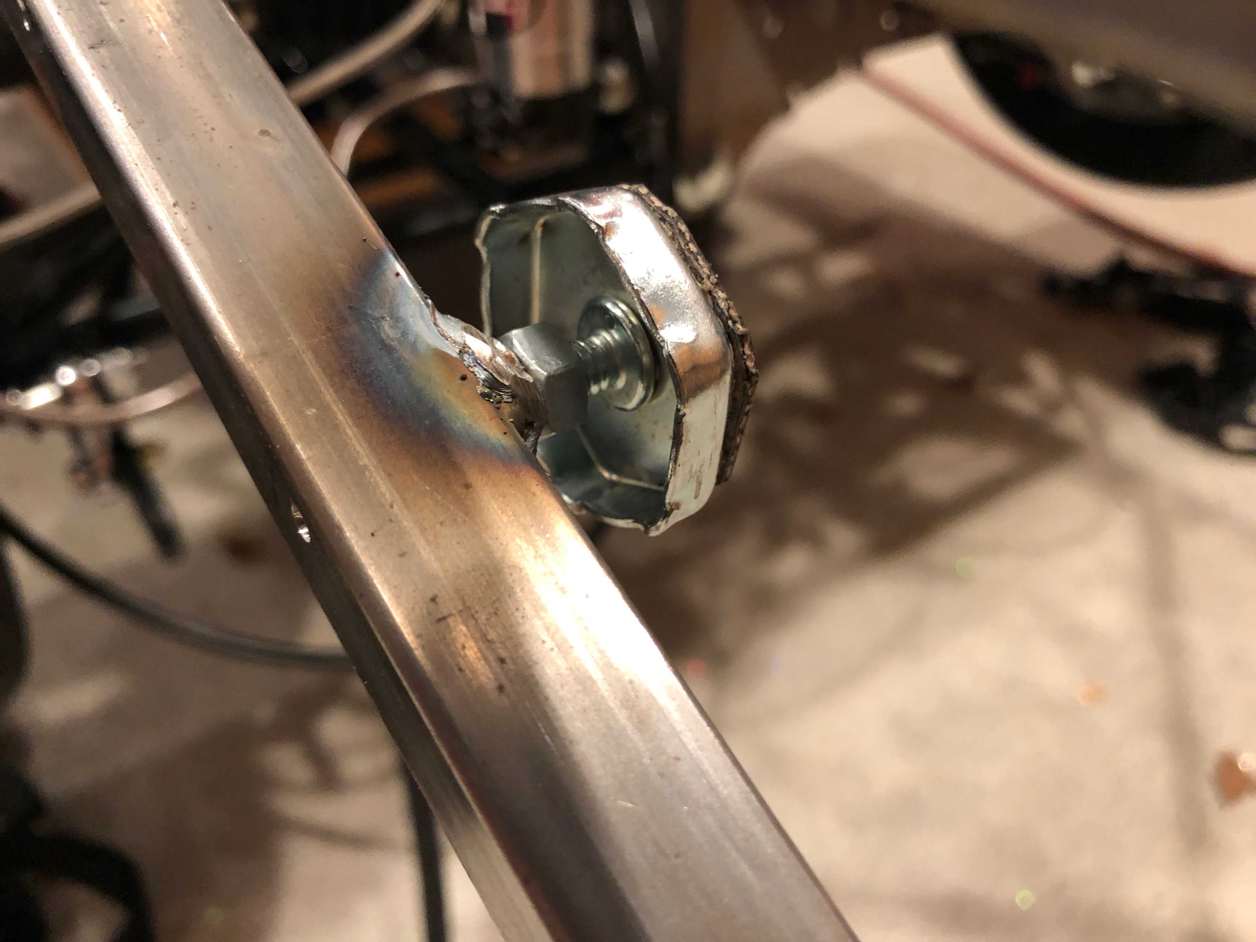
With the final location of the adjustment mechanism determined, I drilled the upper hole and installed a riv-nut. I then taped the ends of the cable and cut off the excess. I’ll replace the tape with a different cable termination during final reassembly.

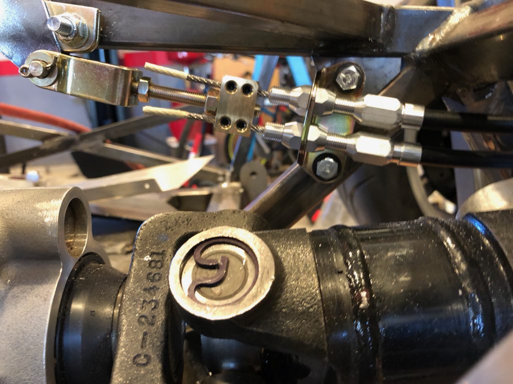
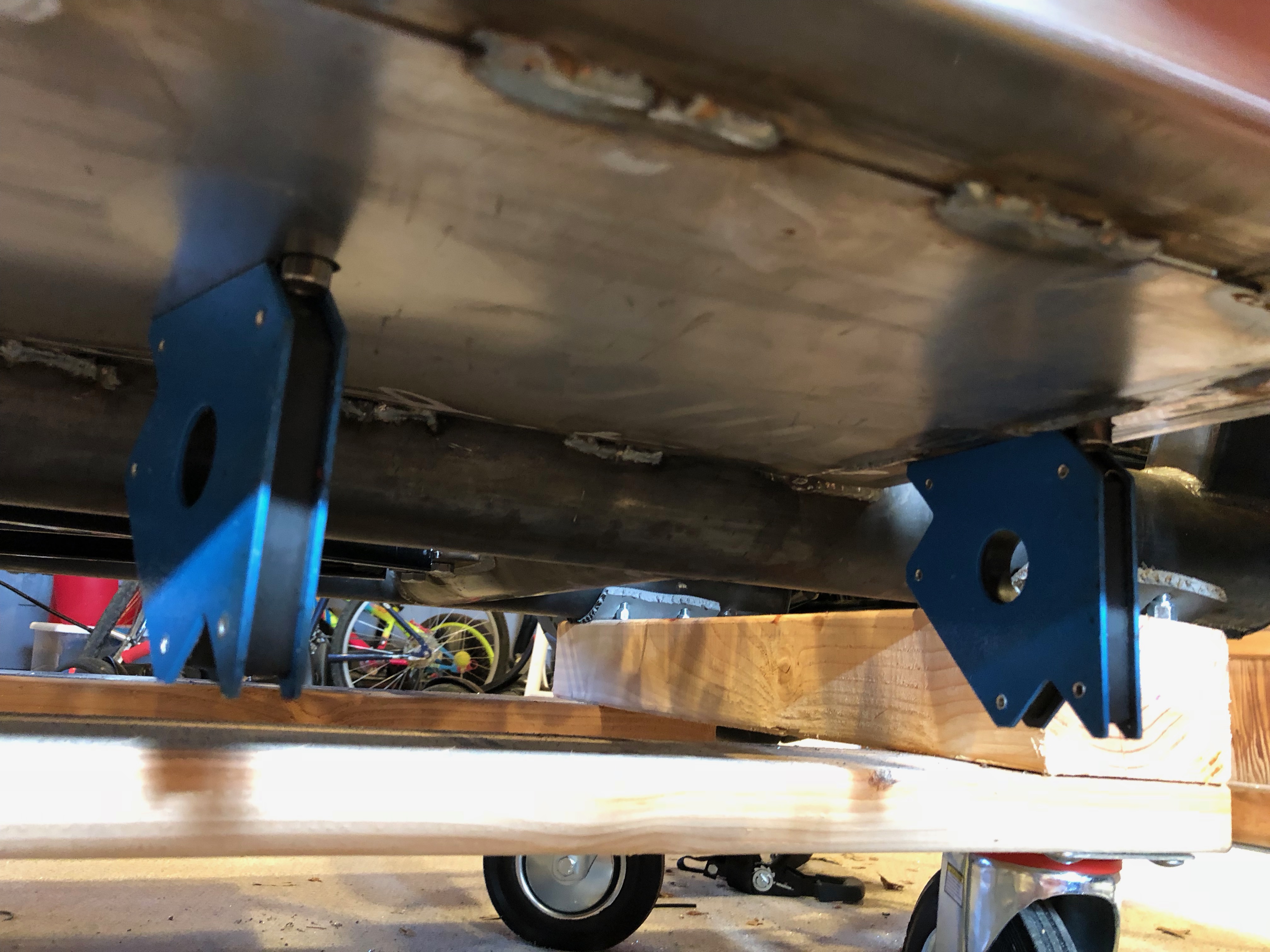
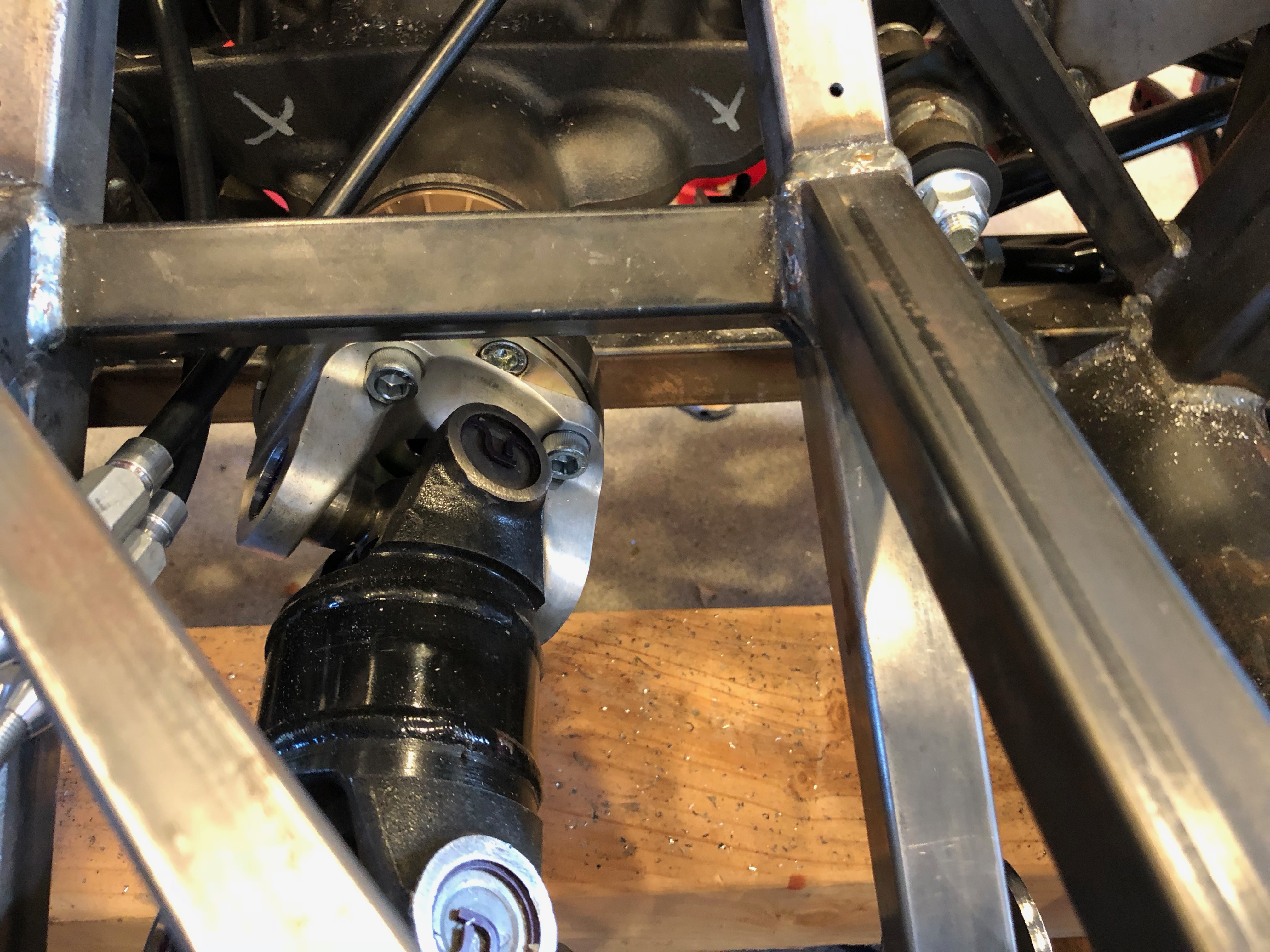
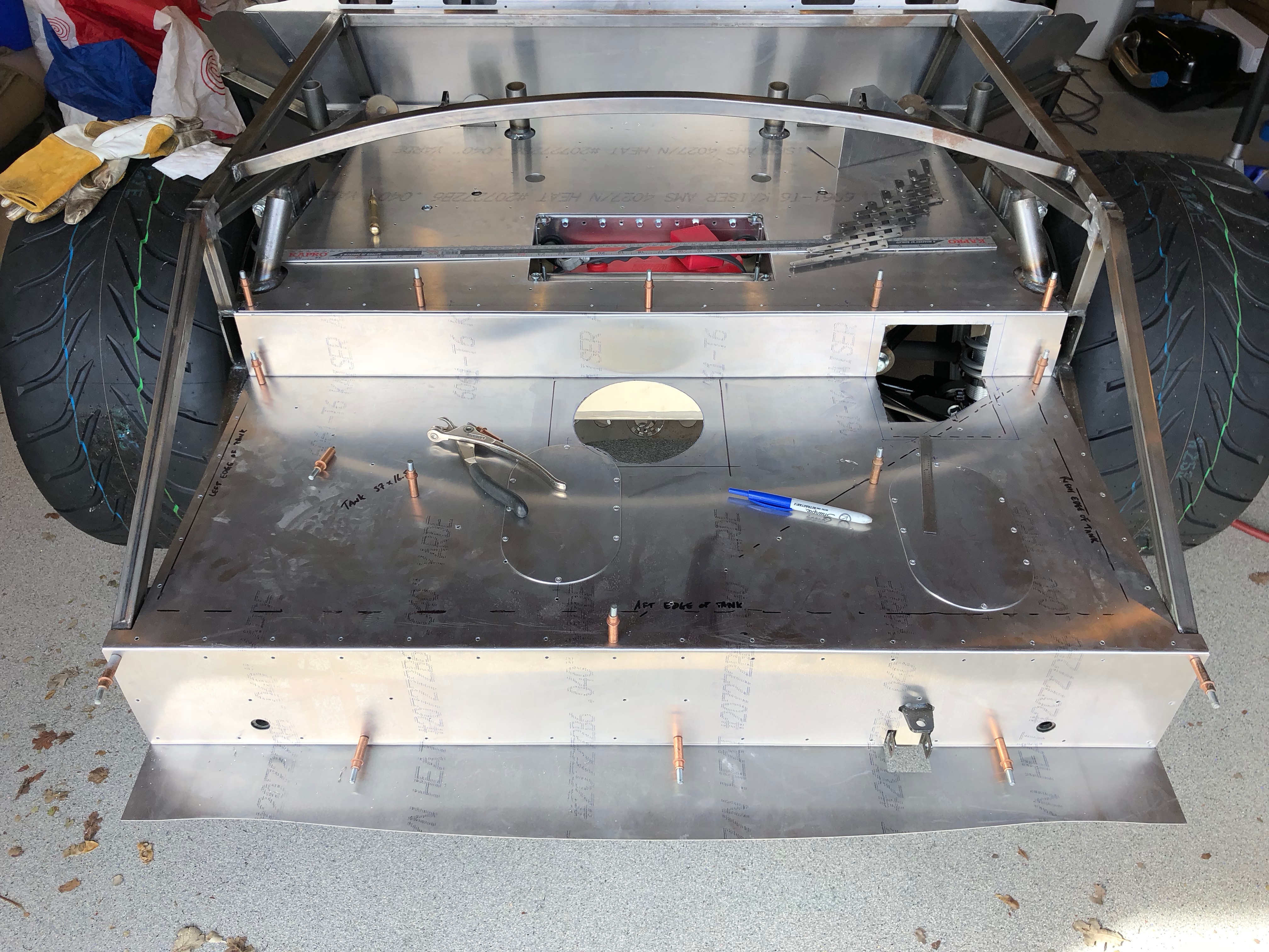
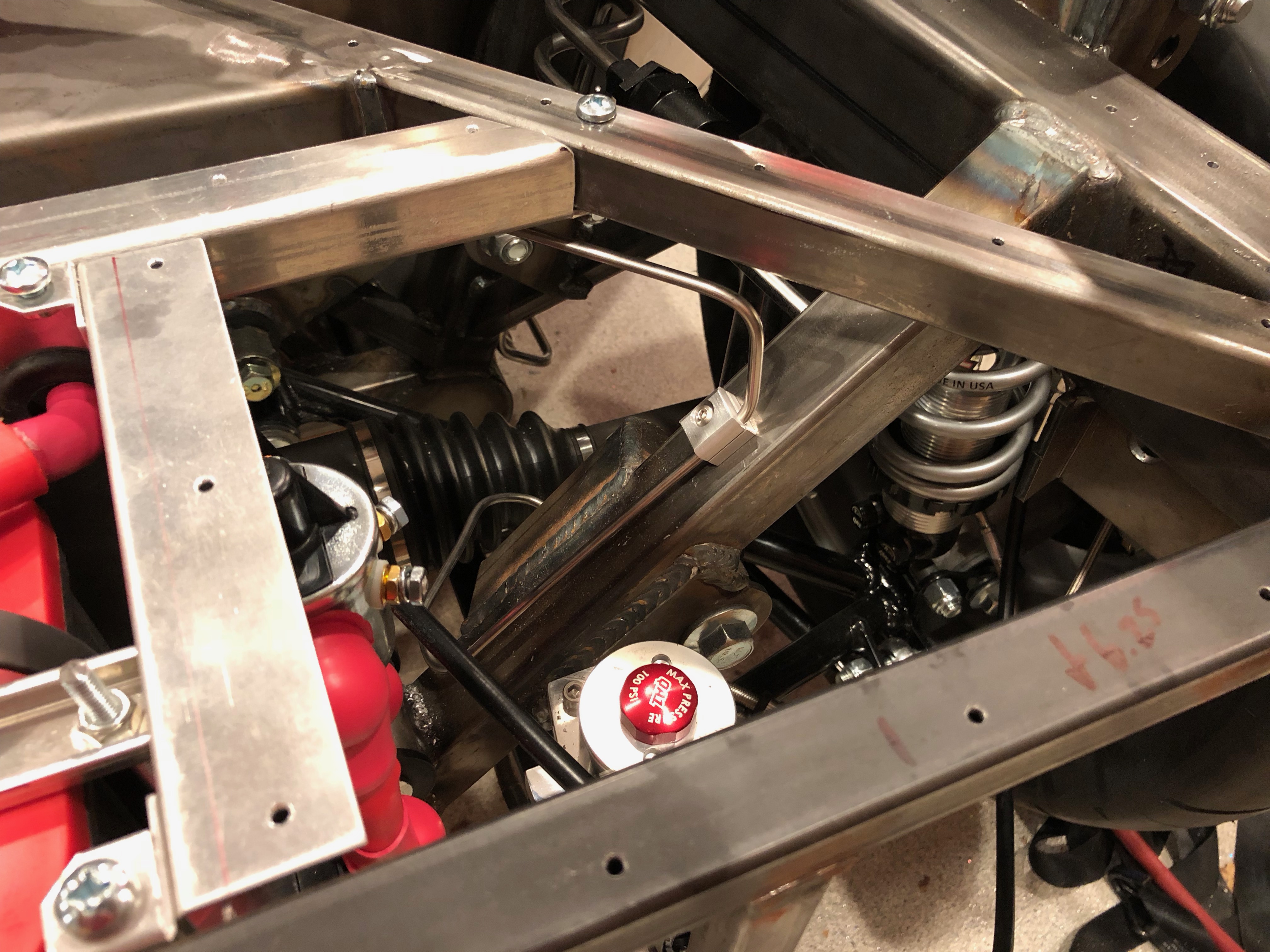
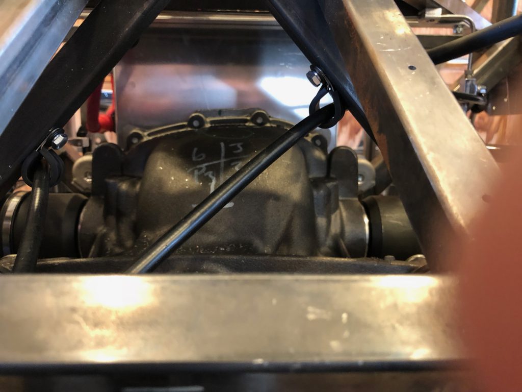
The cables exit the adjuster very close to the driveshaft. I want to add additional support for the cables to ensure they’ll never make contact with the driveshaft.

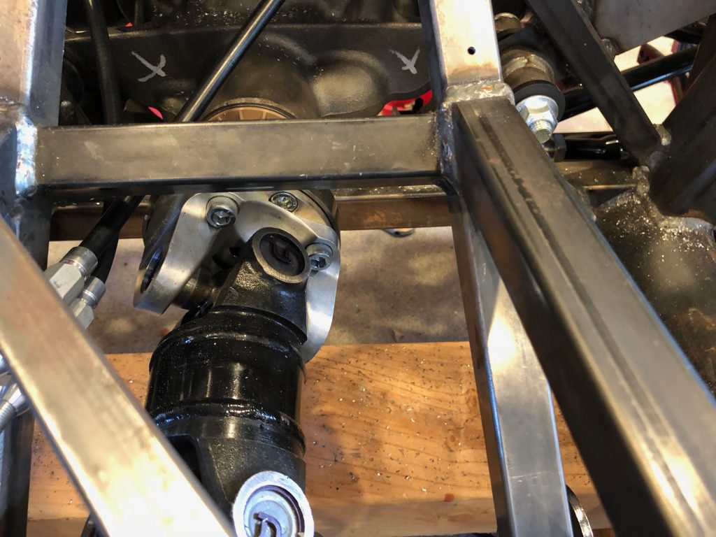
I added a couple of adel clamps above the differential to ensure the cables can’t drop and come in contact with the driveshaft. There’s now no way to even flex the cable enough to contact the driveshaft.

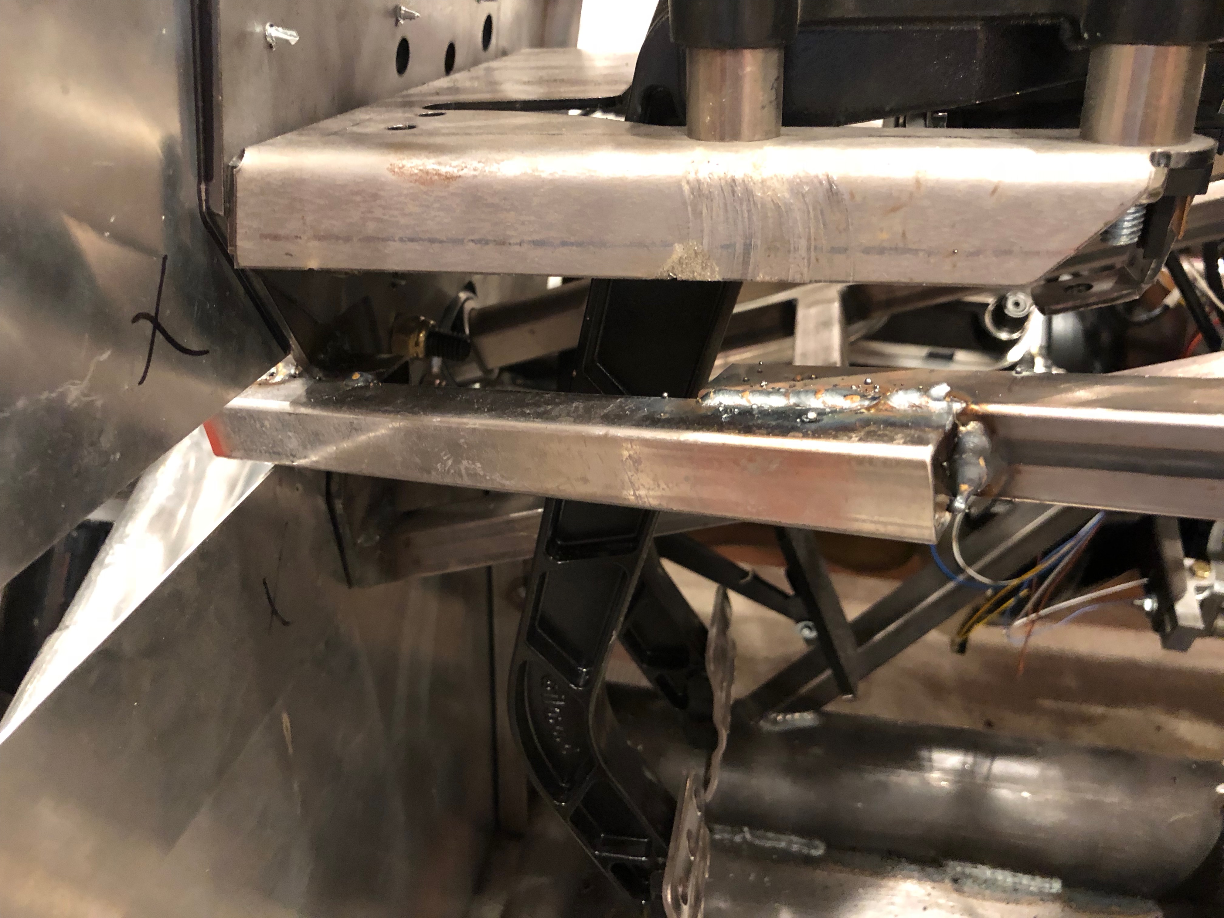
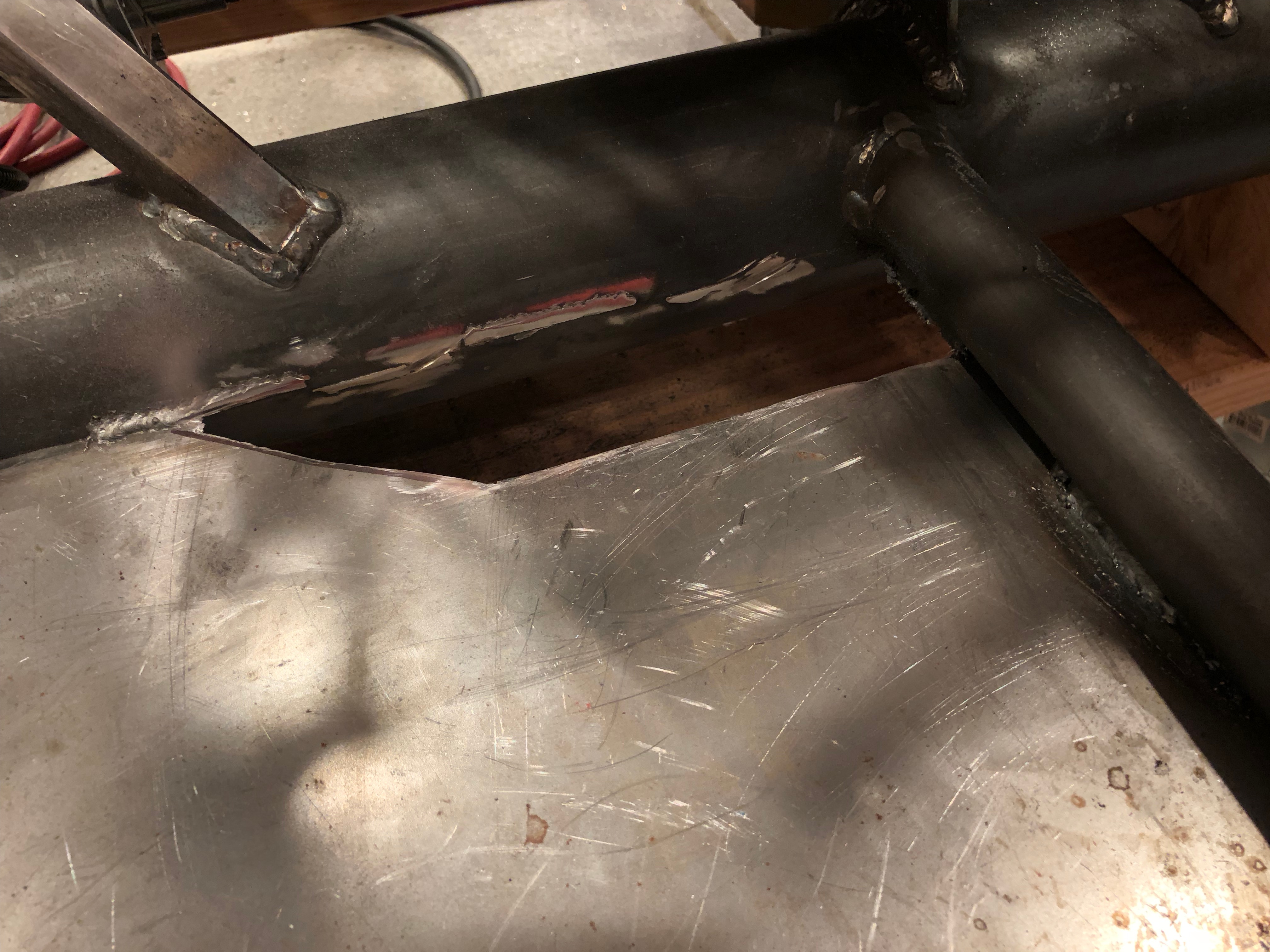
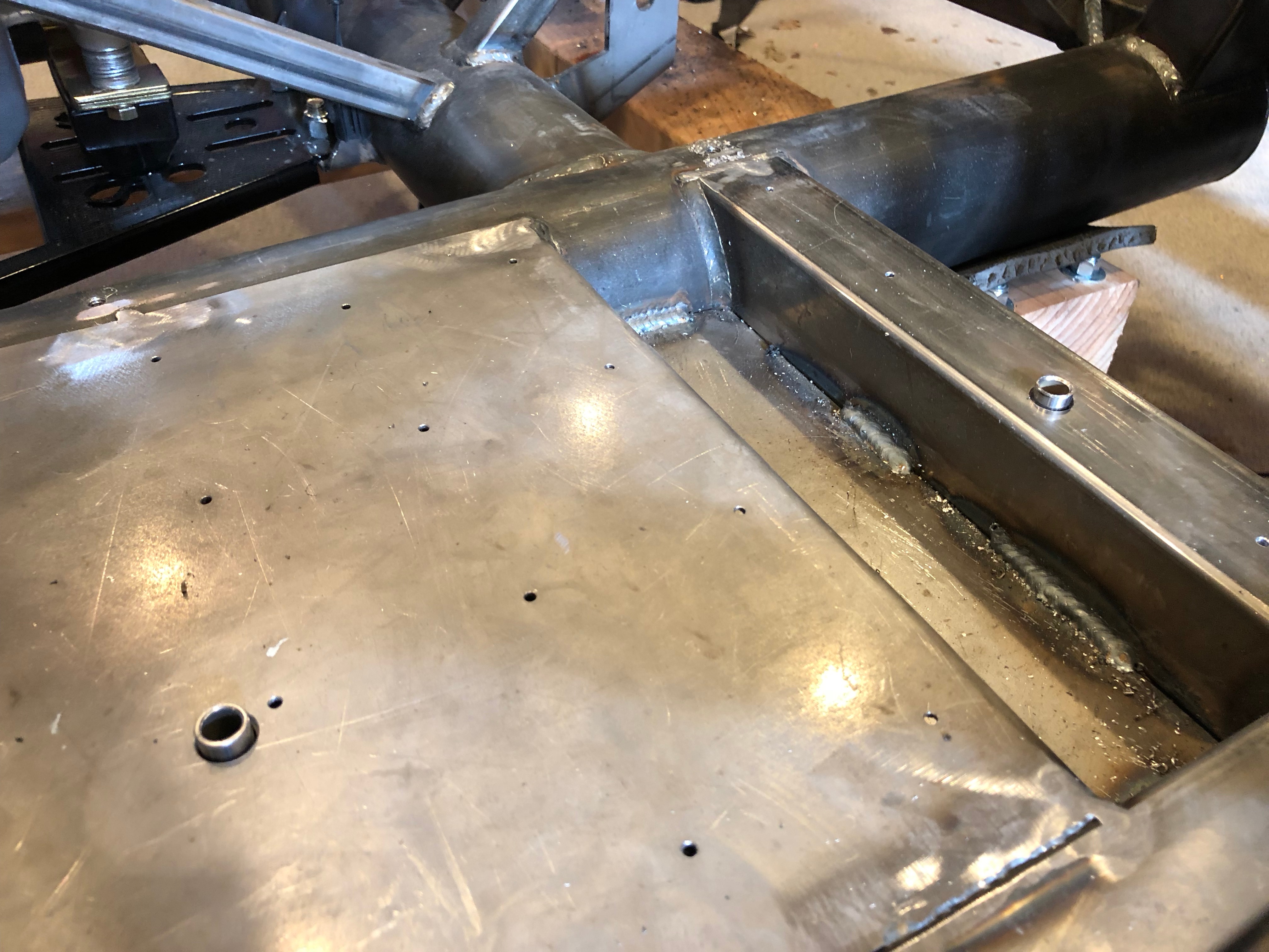
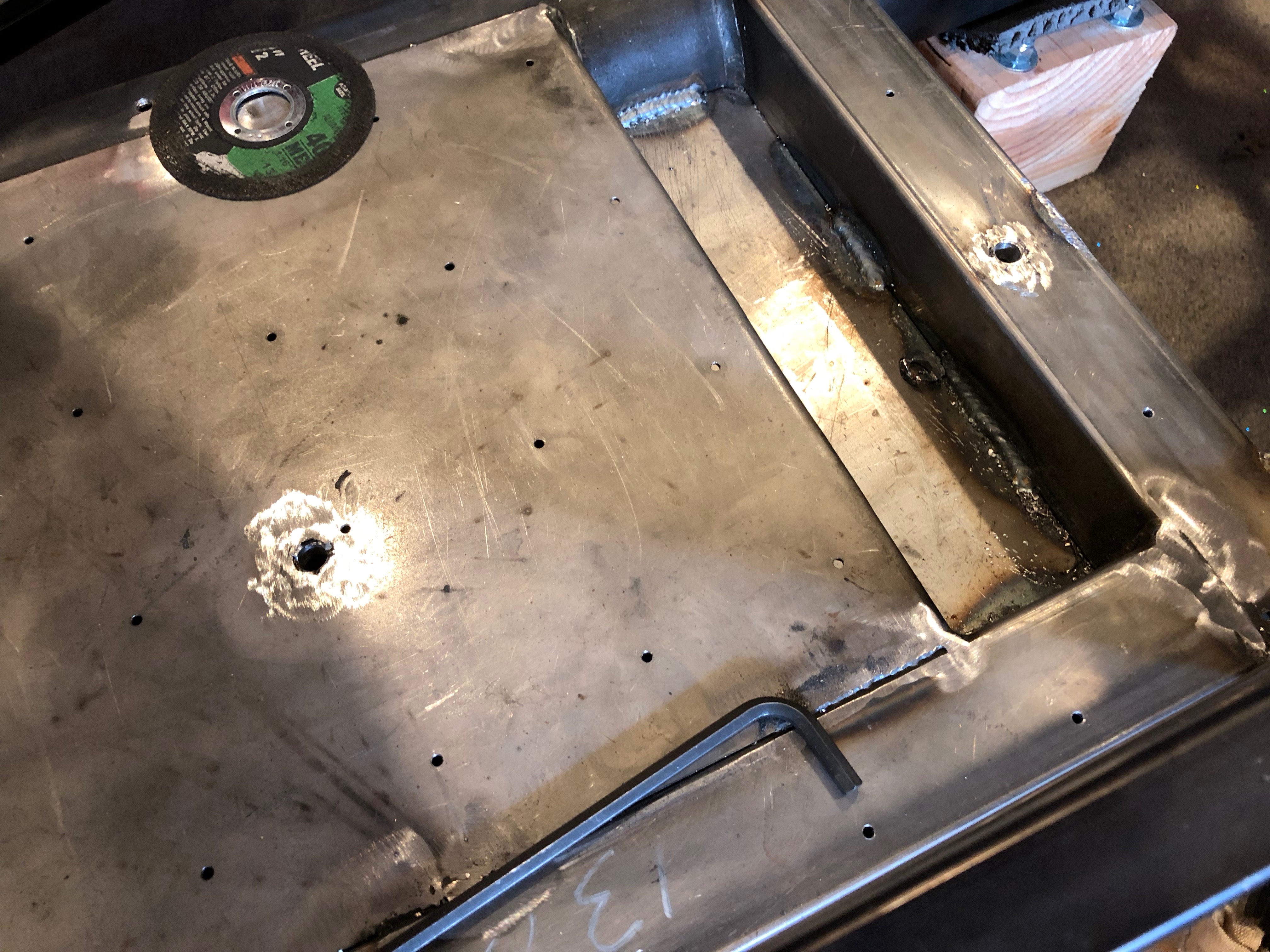
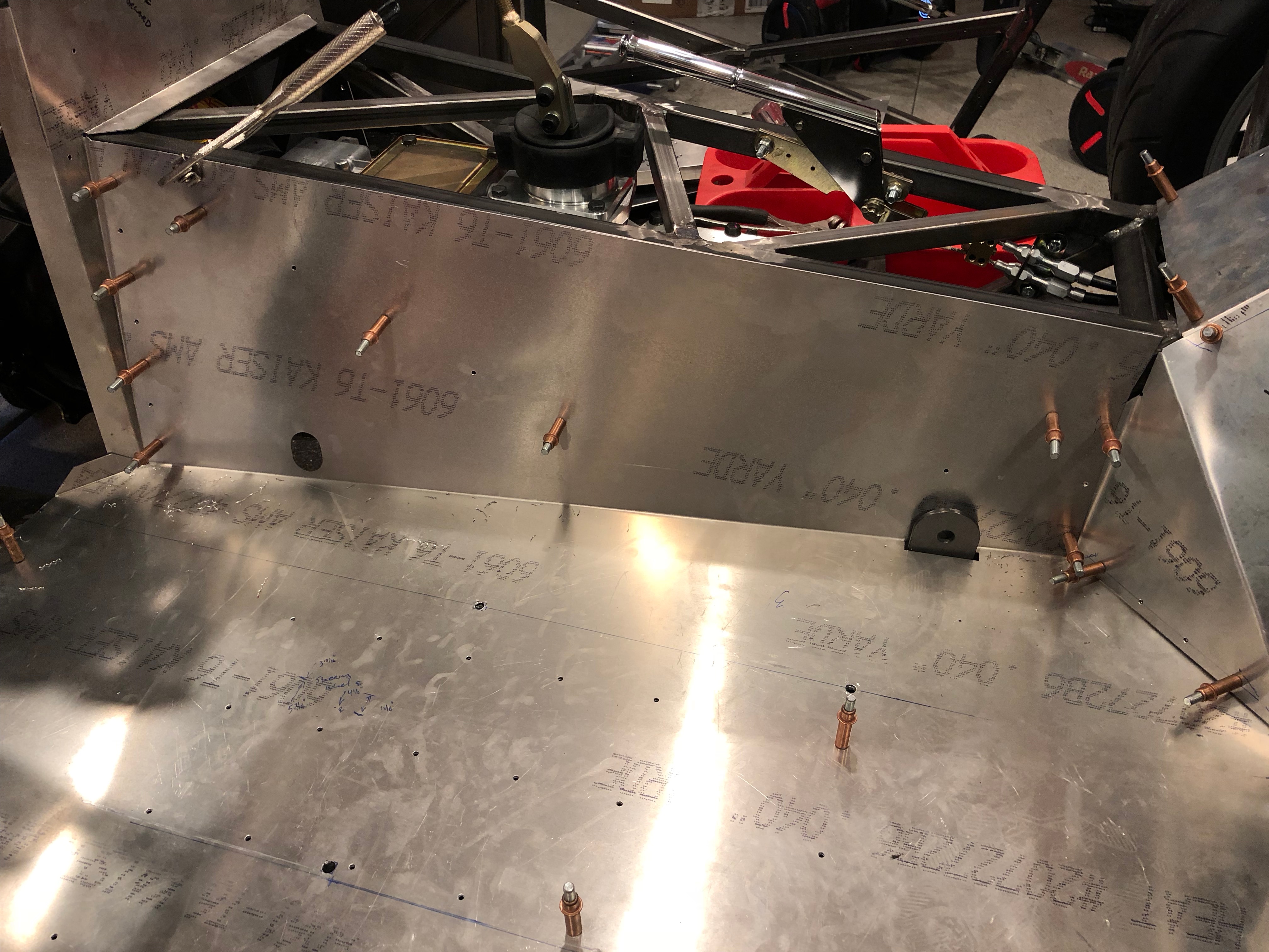
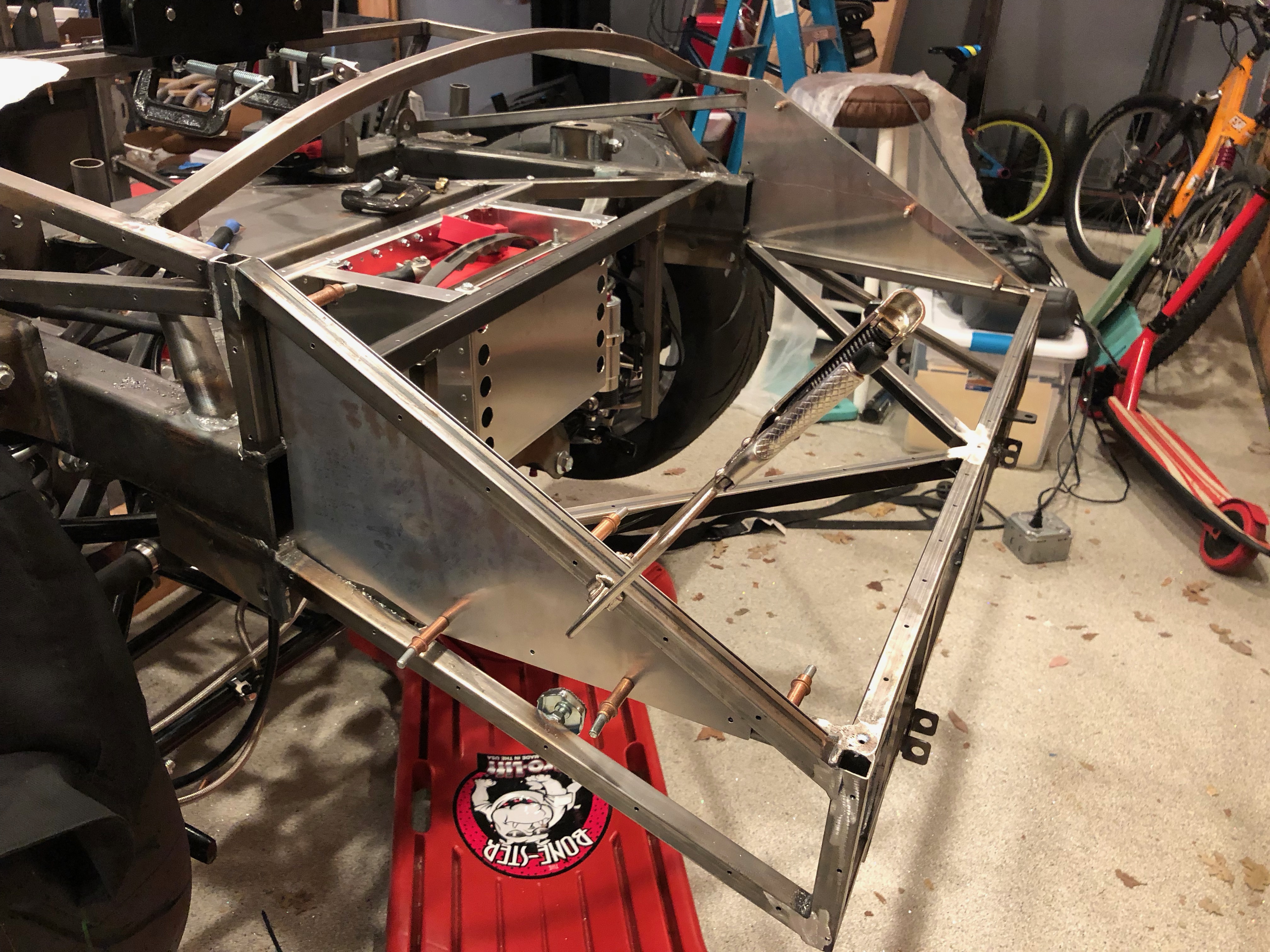
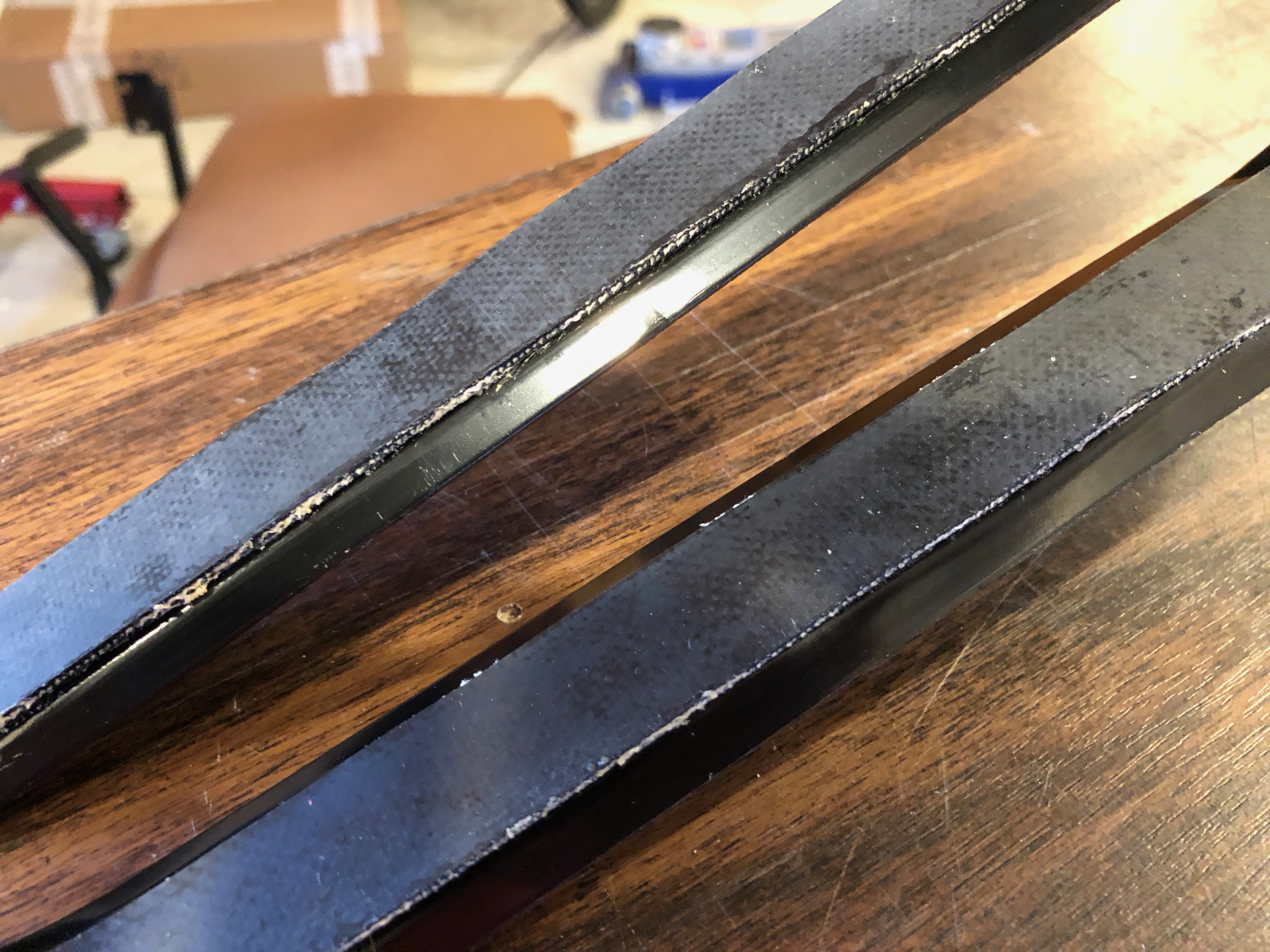
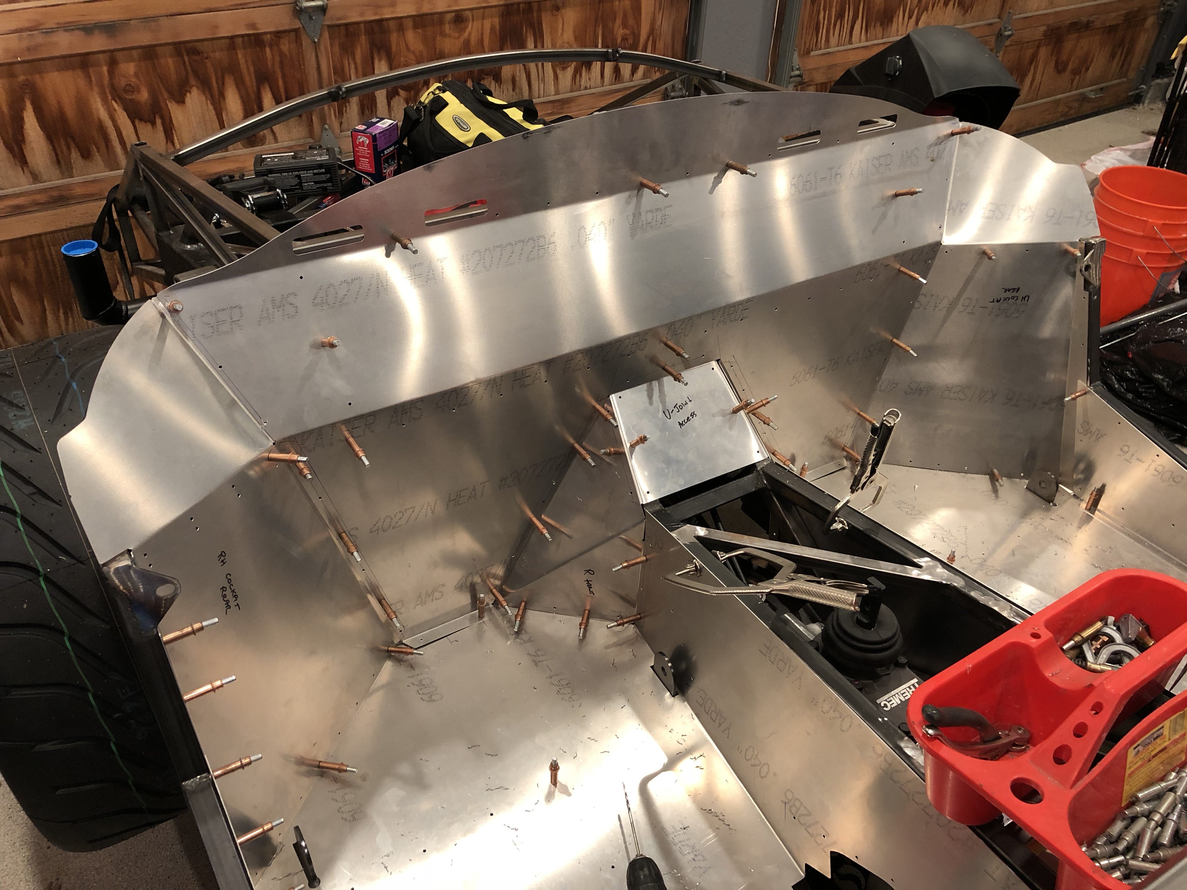
With the shifter and parking brake in place, I trimmed and reinstalled the old cross member in the top of the transmission tunnel.

Here’s the finished transmission tunnel. I couldn’t weld the underside, but I’ll take care of that when the chassis is bare again.

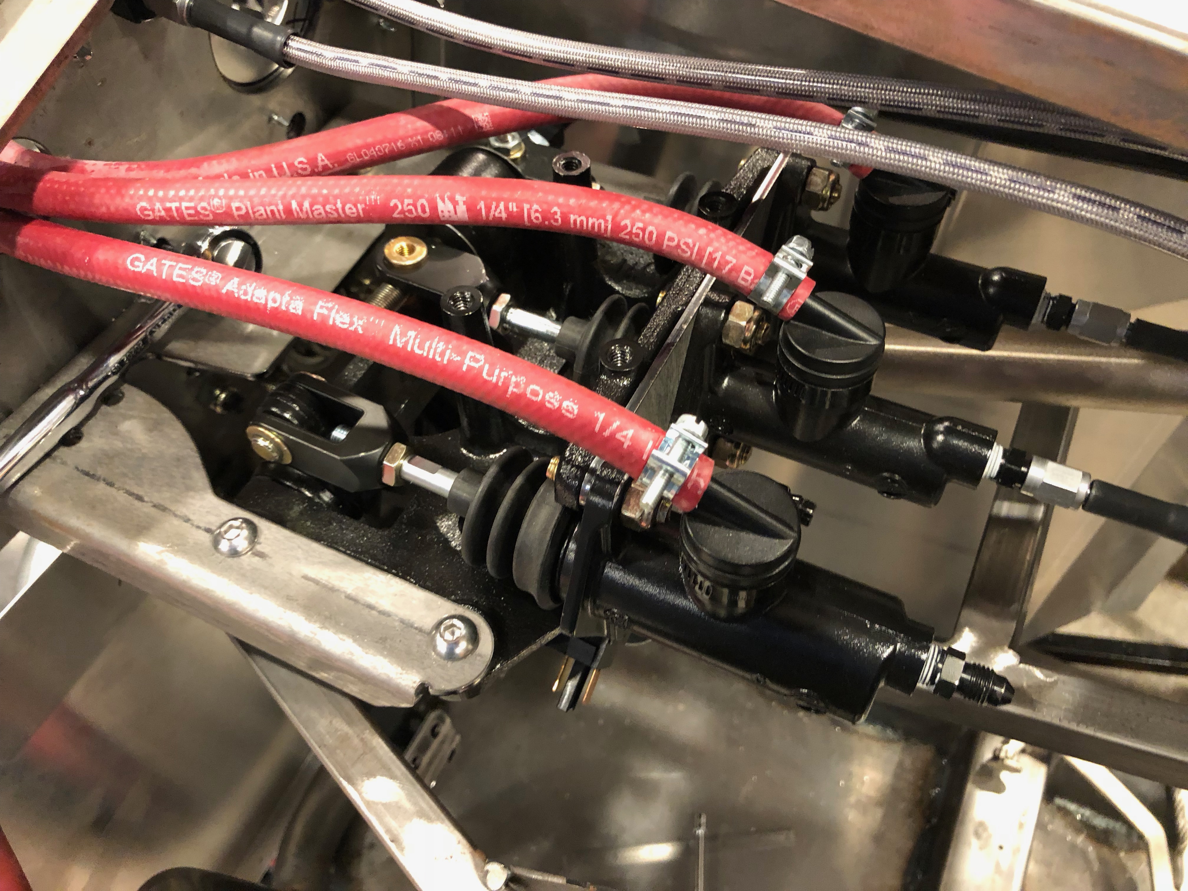
I trimmed 1/2″ from the pushrods of each master cylinder. You can see that the jam nuts are nearly bottomed out on the shafts.

This moves the pedals forward another 2″ or so. They now sit about 5.75″ forward of the firewall. If this isn’t sufficient clearance, there’s plenty of adjustment to move them farther away from the firewall.

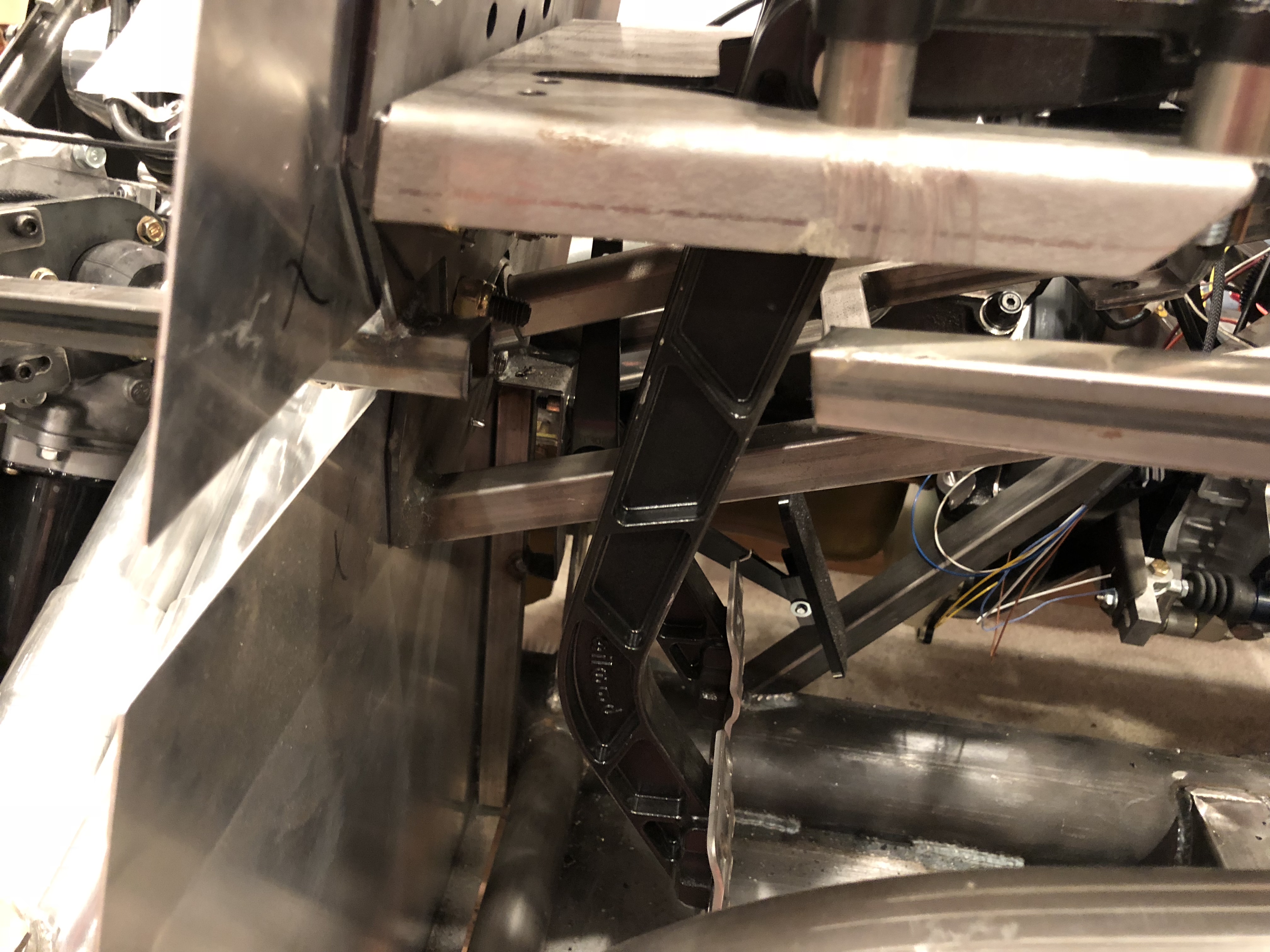
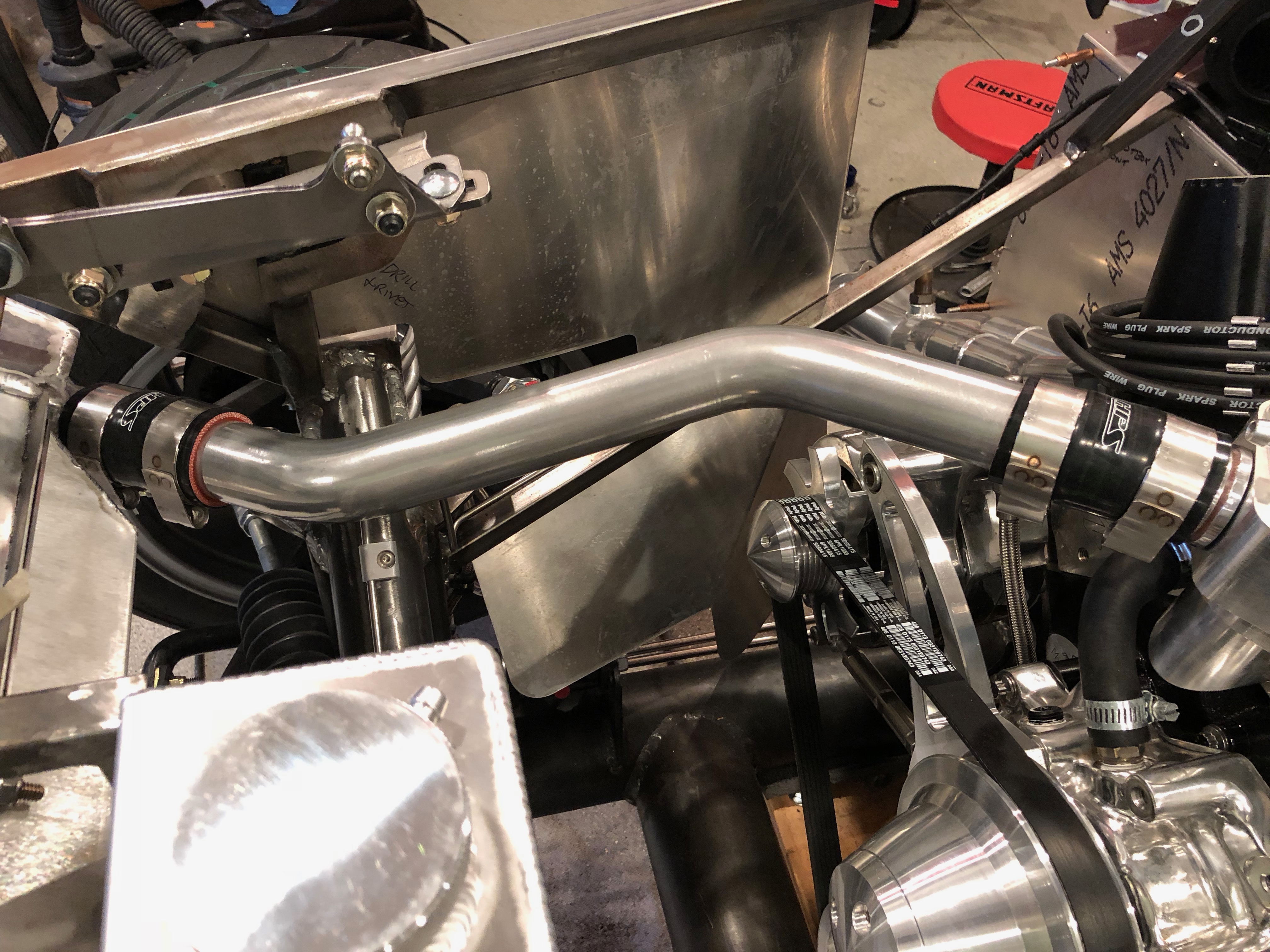
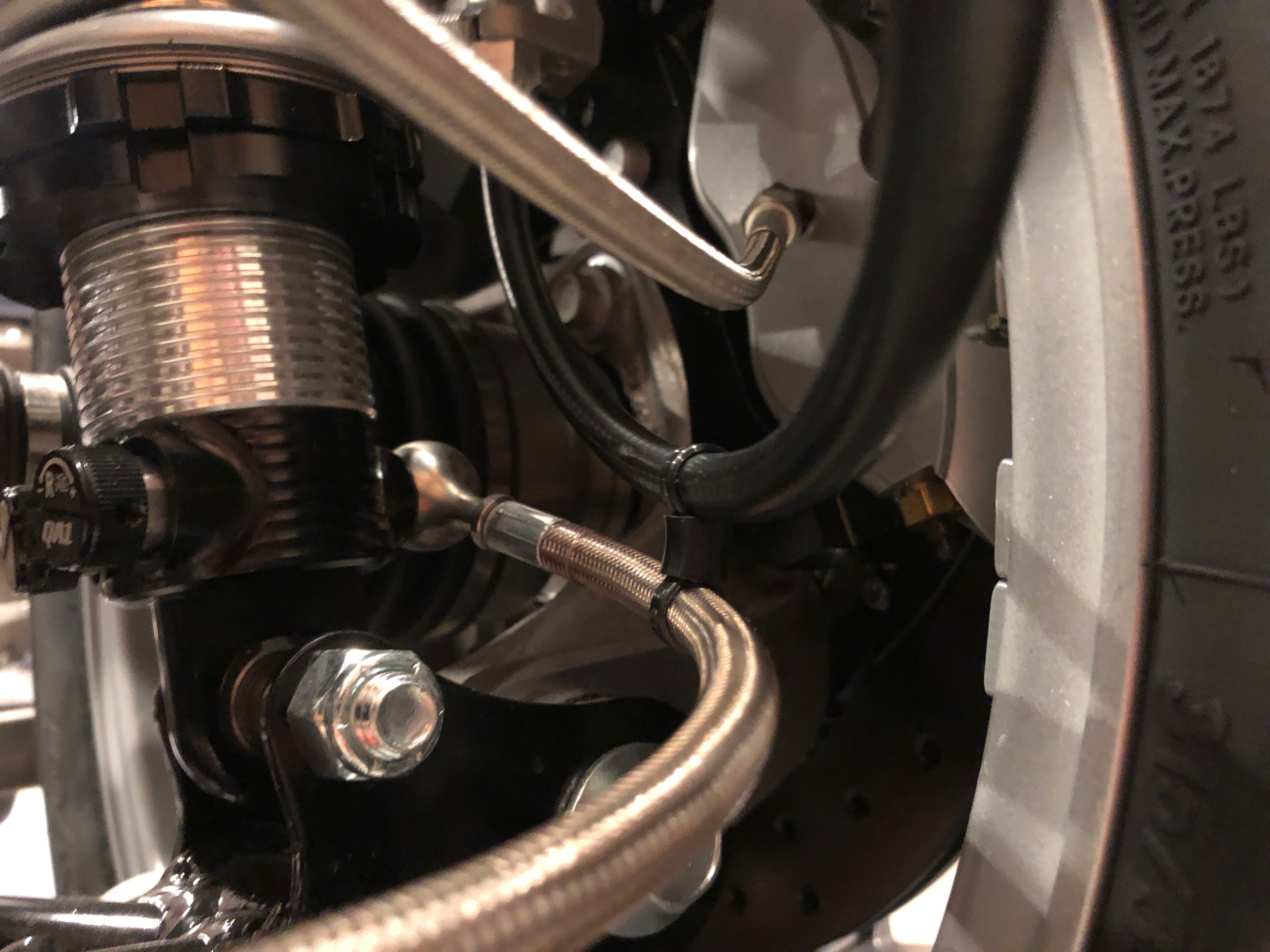
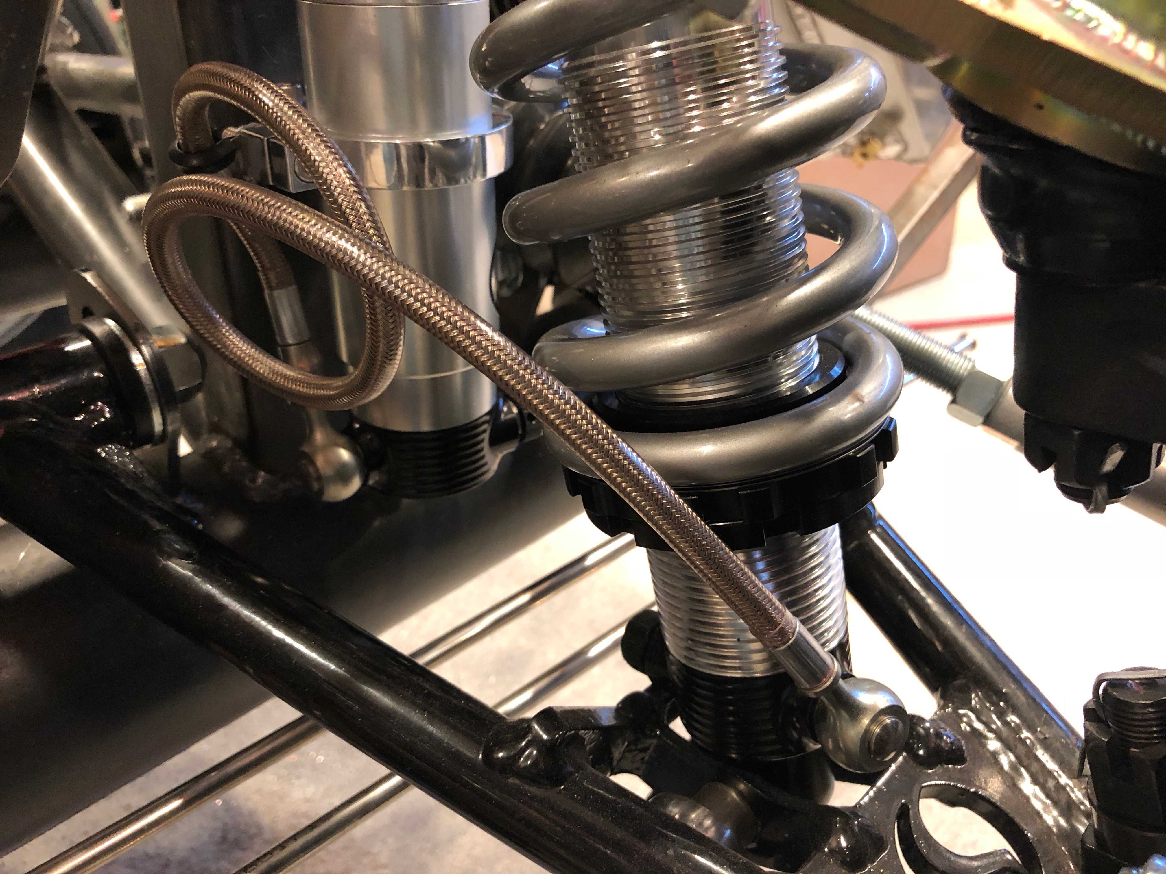
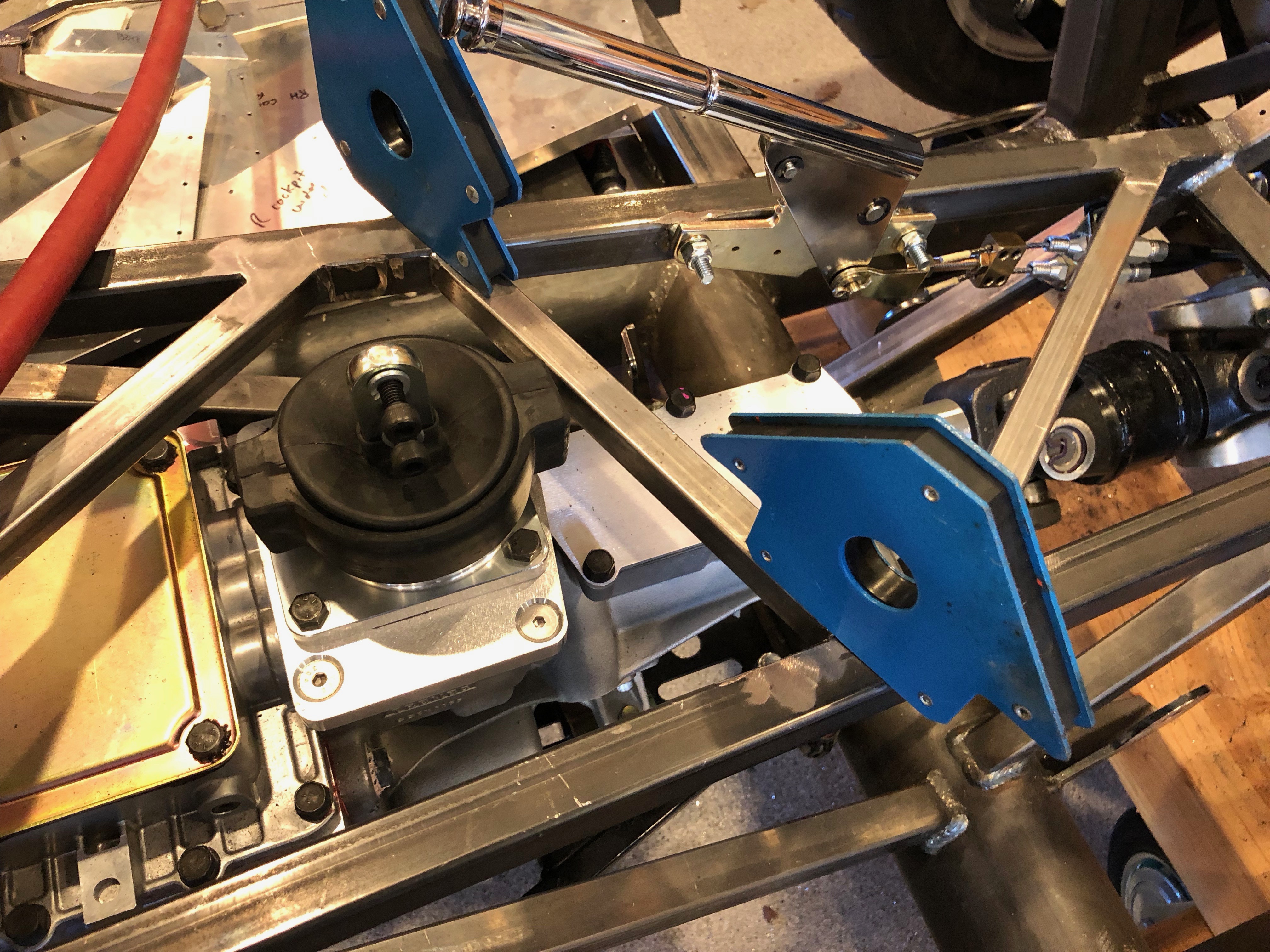
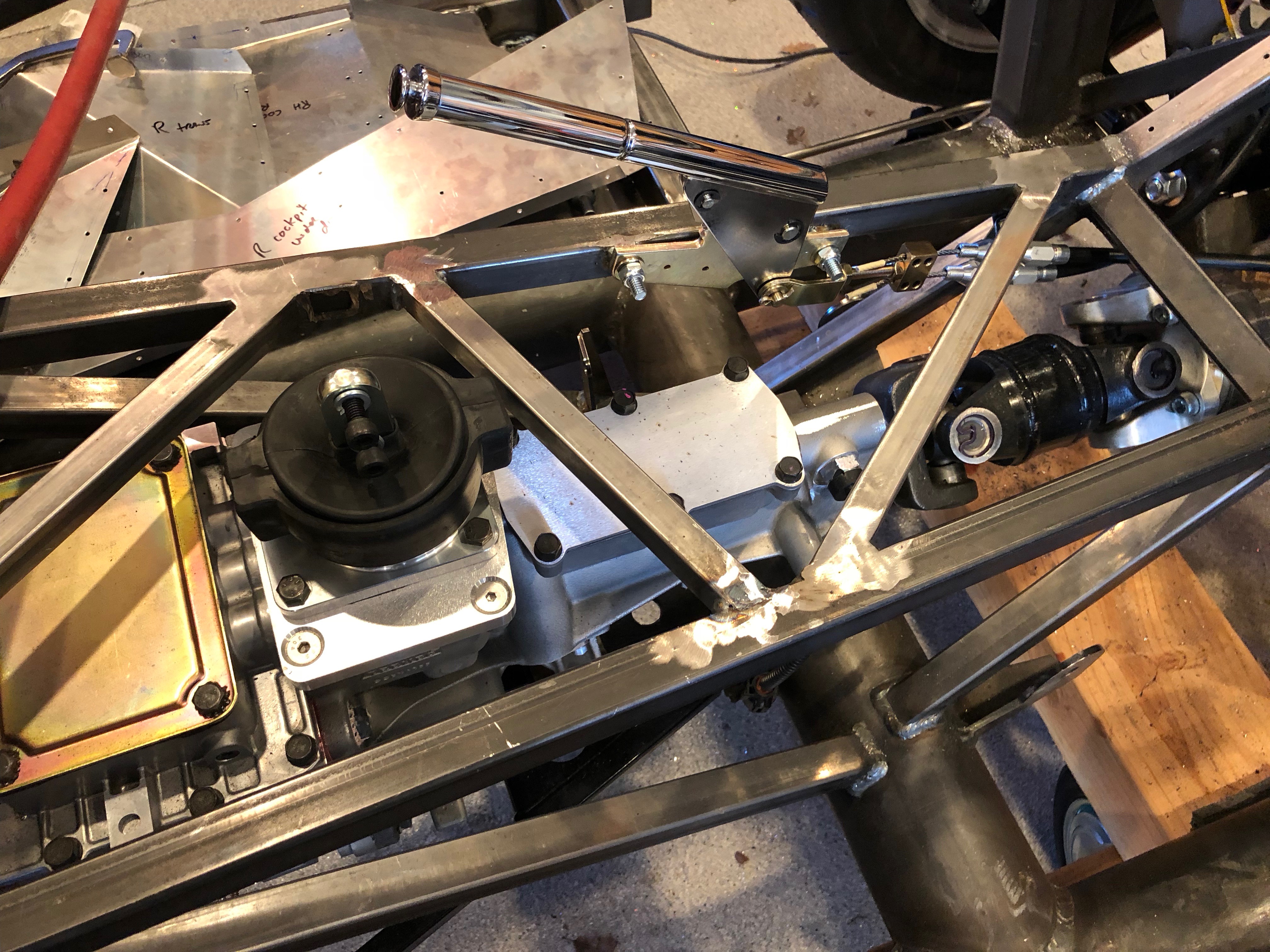
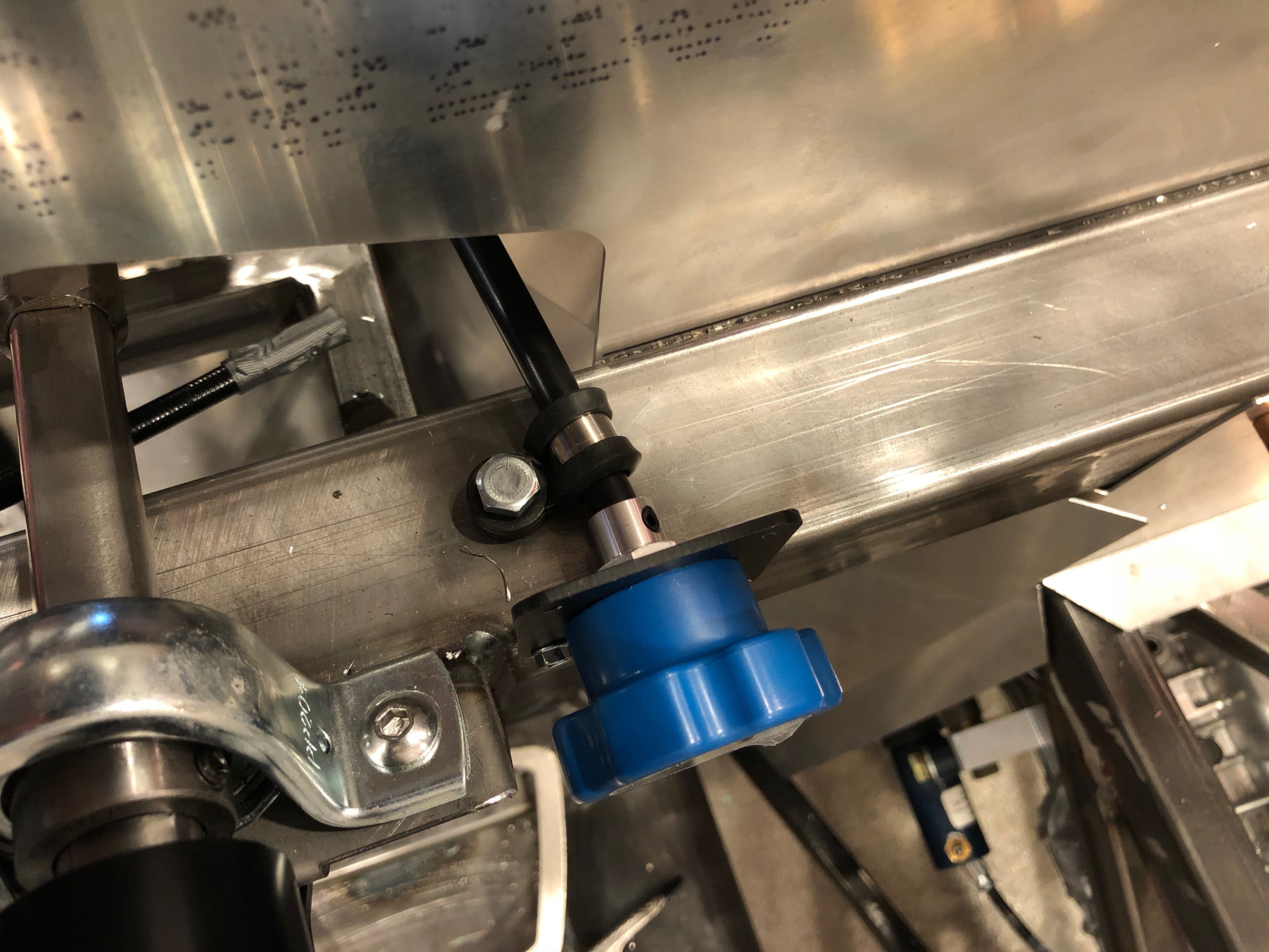
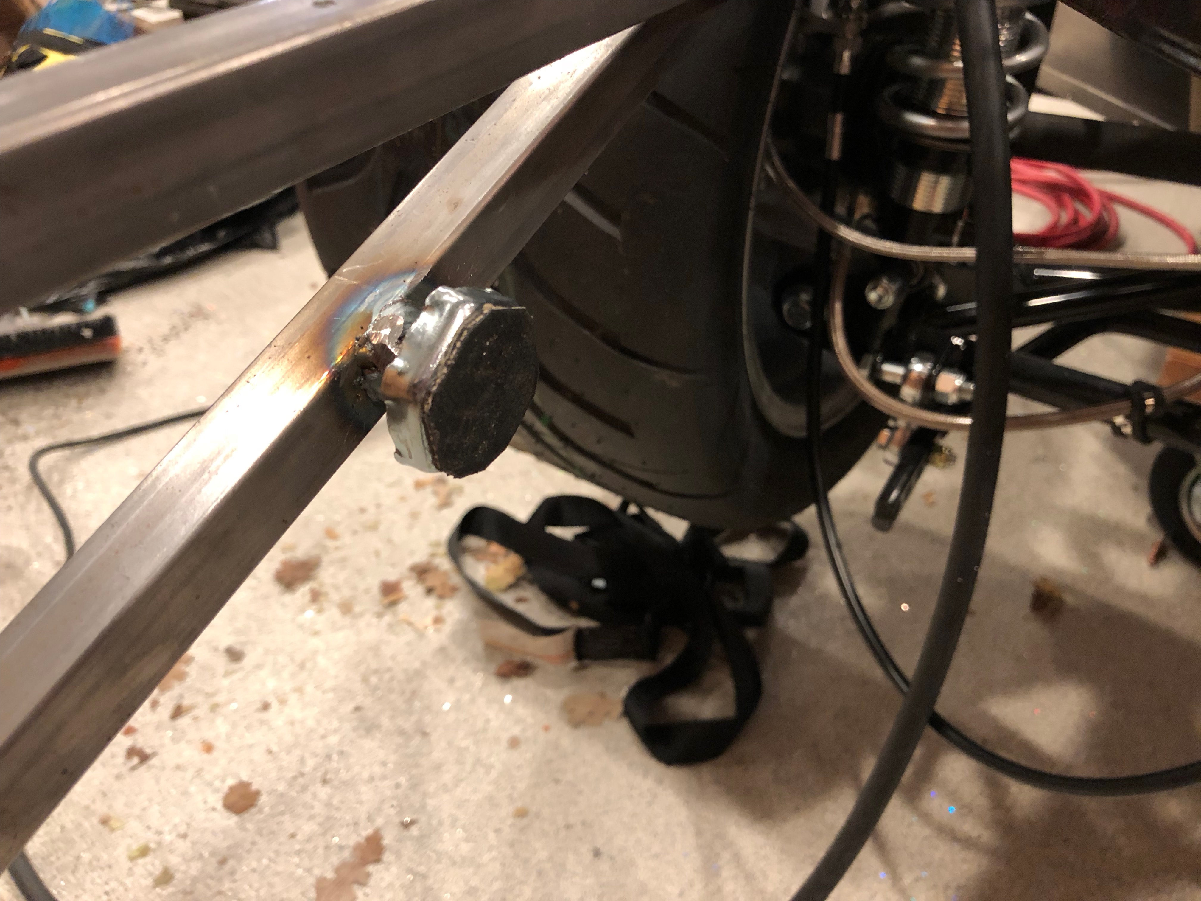
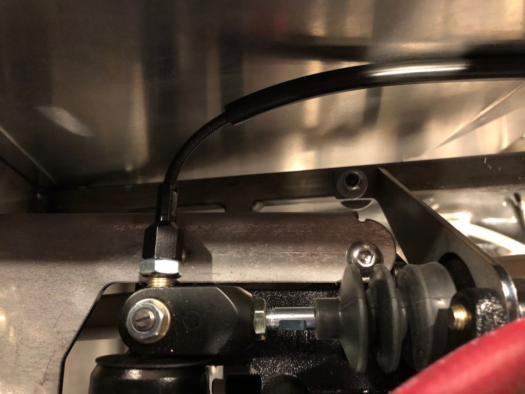
I then installed the adjustment cable. I left a section without the housing to allow a tighter bend radius. I was worried that this was going to be too tight of a bend and that I was going to have to go through the sidewall of the footbox and into the engine compartment, but this works very well.

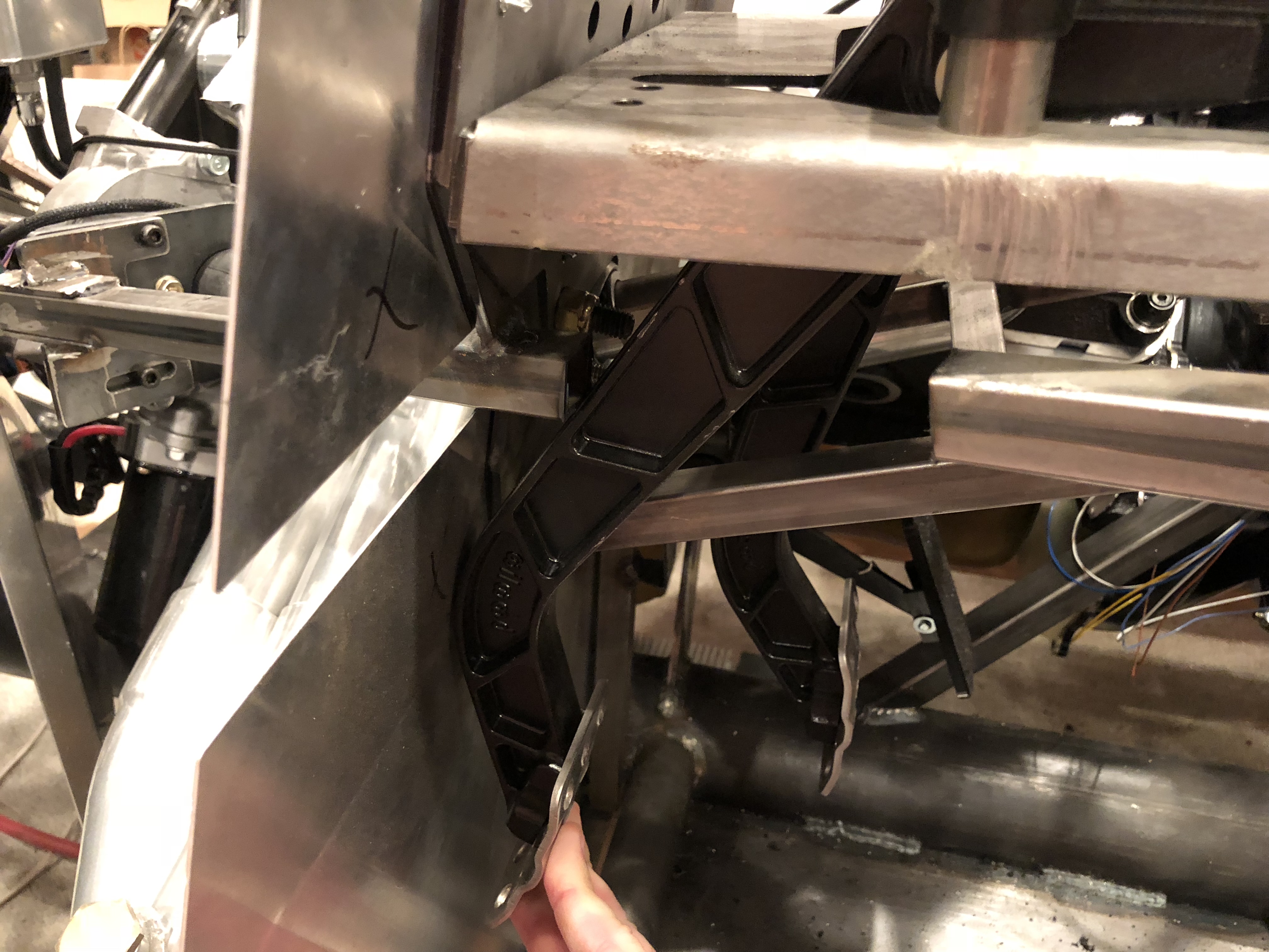
I installed the other end just to the right of the steering shaft. I could only drill through the lower two holes, so I added an adel clamp to further secure the assembly. It’s plenty rigid, especially for the infrequent use this will see.

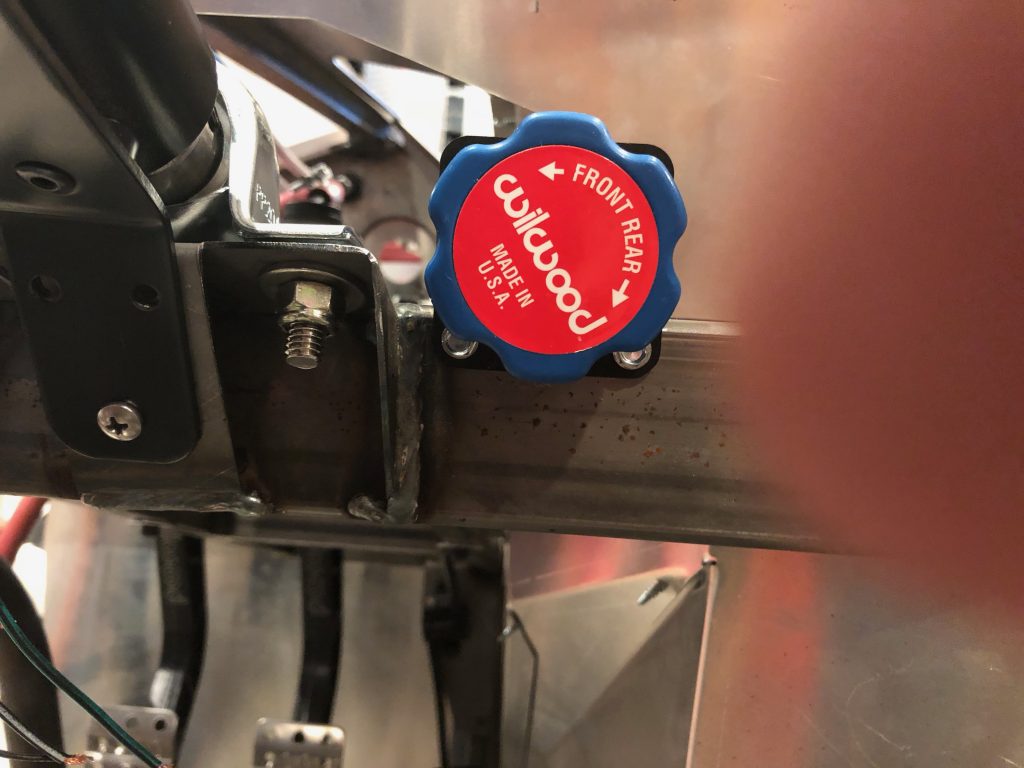
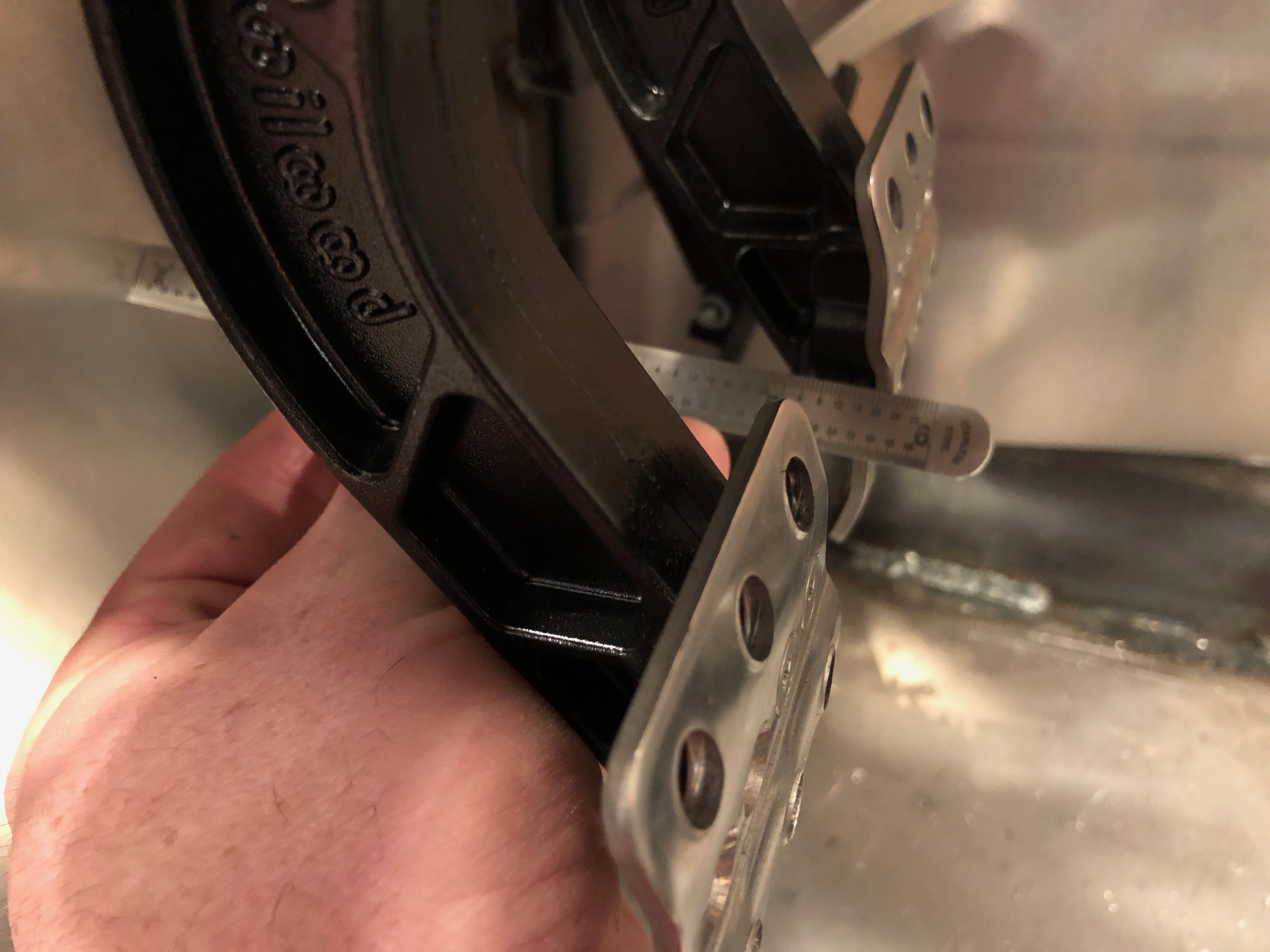
Finally, I installed the appropriate label to mark the direction of rotation necessary to achieve the desired biasing. I won’t be able to see the label from the seat, but it’s pretty easy to remember that right is rear.

Trunk Aluminum, Fuel Tank Stabilizers and Rear Brakes

Before I can install the fuel tank for good, I also needed to wrap up the trunk aluminum. I had previously drilled the upper trunk floor, but I never did the same for the lower trunk floor. I started by removing the tank (hopefully for the last time before the final reassembly). I needed to do this so that I could mark the chassis tubes on the underside of this sheet. After laying out all of the holes, I drilled the sheet to the chassis tubes. You can also see that there is a row of rivet holes tying the upper trunk floor to the lower trunk floor.

With the lower trunk floor in place, I cut and bent a piece of scrap aluminum to make the access panel cover for the fuel sender and fuel return and vent fittings.

I drilled this to the floor with a #30 bit for now. I’ll open these up for the right size screw before installing nutplates.

I also cut out and drilled an access panel cover for the fuel pump and supply fittings.

The fuel tank is narrower than the cavity in the chassis that it fits within, but I don’t want the fuel tank to be able to slide from side to side. To prevent this, I drilled a 1/4″ hole in the lower diagonal tube on the inside face and welded on a 1/4-20 nut.

I threaded a leveling foot with threaded stud into the nut. I had previously bonded a piece of the same reinforced rubber sheeting onto the foot where it will contact the tank.

You can see on the other side that there is a run nut threaded onto the shaft as well. Once the tank is installed, I can tighten the foot against the tank and lock it into position with the jam nut.

Before reinstalling the tank, I wanted to wrap up the rear brakes. I started by adding a brake line clamp on the right diagonal tubing. Unfortunately, when I was trying to wrap up the other end of this piece of tubing, I botched the flare. I don’t think the tubing is salvageable, so I’ll probably have to fabricate a new piece.

Fuel Tank Straps and Trunk Aluminum

After reshaping the fuel tank straps to better fit the angles of the new fuel tank, I used some contact adhesive to bond some strips of reinforced rubber sheeting to the inside surfaces where it will contact the tank.

While waiting for those to cure, I installed the outer trunk side skins. After marking the chassis tubes, I laid out for the rivet holes and drilled them to the chassis.

Cockpit Rear Wall and Emergency Brake Hole Cover

I finished drilling the rear wall to the upper cross member and adjacent aluminum panels.

Since I’m moving the emergency brake, I needed to make a cover for the old opening. The kit comes with two different front panels for the driver’s side foot box, so I took the unneeded one and cut a piece off the bottom to cover the hole. I’ll match drill this to the existing holes that tie the transmission side panel to the chassis and add some additional holes around the perimeter.

More Cockpit Aluminum

I continued working on the cockpit aluminum by fitting the rear outer panel on the driver’s side.

I then drilled the u-joint cover plate to the chassis and the rear inner panels to the cover plate.

Finally, I drilled the rear wall to the floor and the lower steel cross member on the chassis. I still need to drill this to the inner and outer rear panels and the upper steel cross member.