Installed Pedal Box

Jenn’s been sick since we got back from vacation. She’s disappointed to not be able to work on the car, but she wants to see some progress, so she’s been fine with me working on the car alone the last few days.

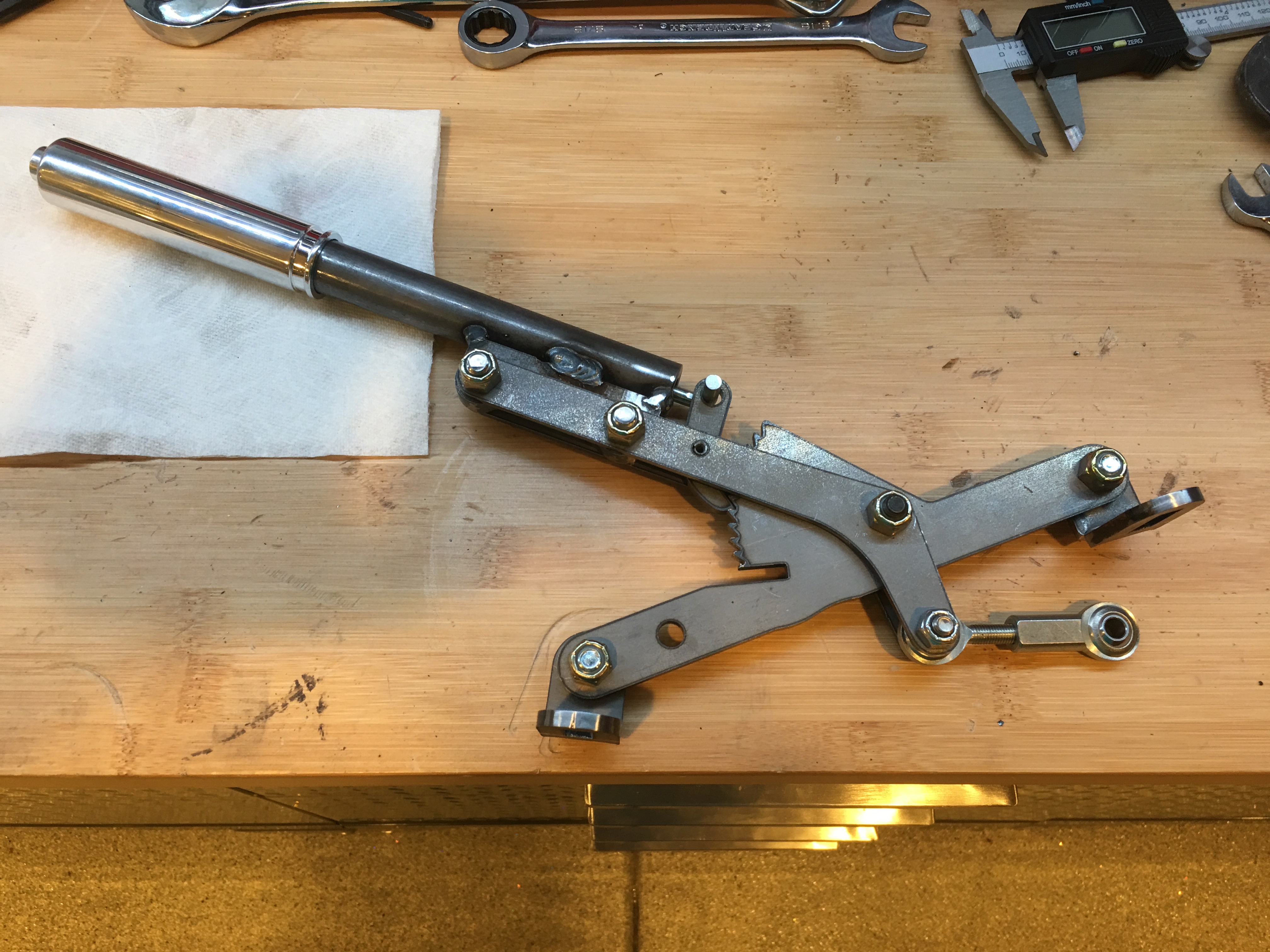
Next up is to install the pedal box. The complete kit comes with the Wilwood pedal box that contains the brake and clutch pedals. The brake pedal is set up to depress two master cylinders (one for the front brakes and one for the rear). The clutch pedal can use a master cylinder for those (like us) who are using a hydraulic clutch, or it can be configured to use a clutch cable for those running a manual clutch.

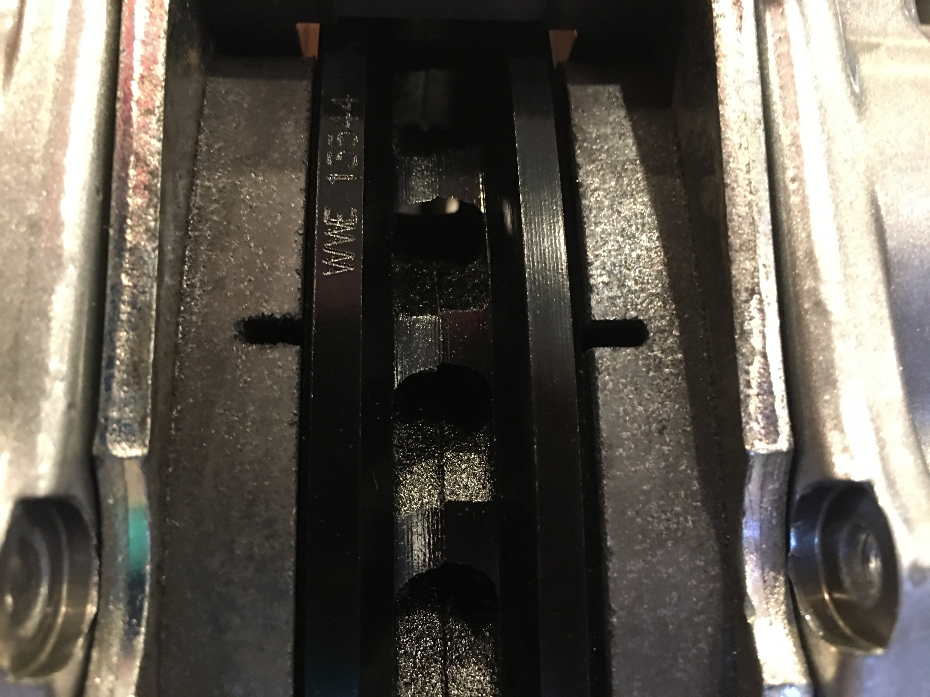
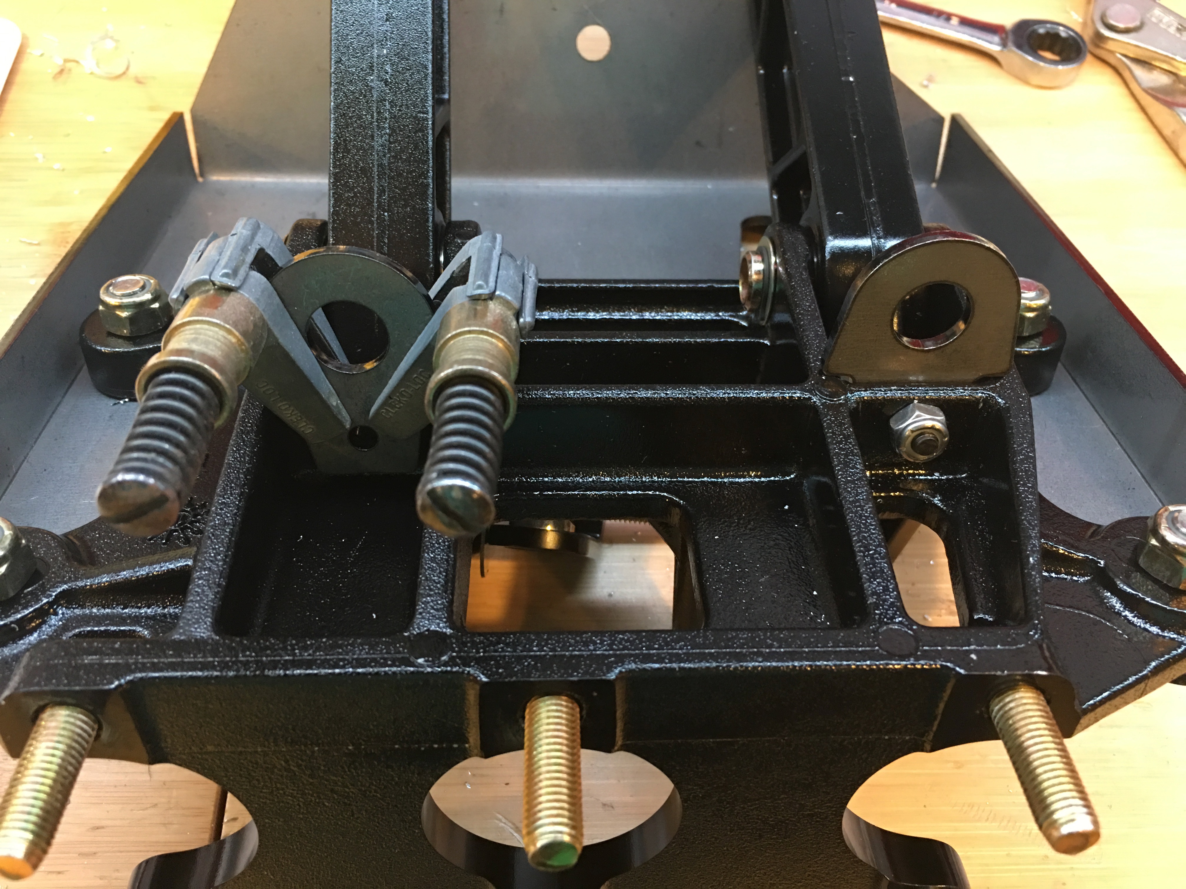
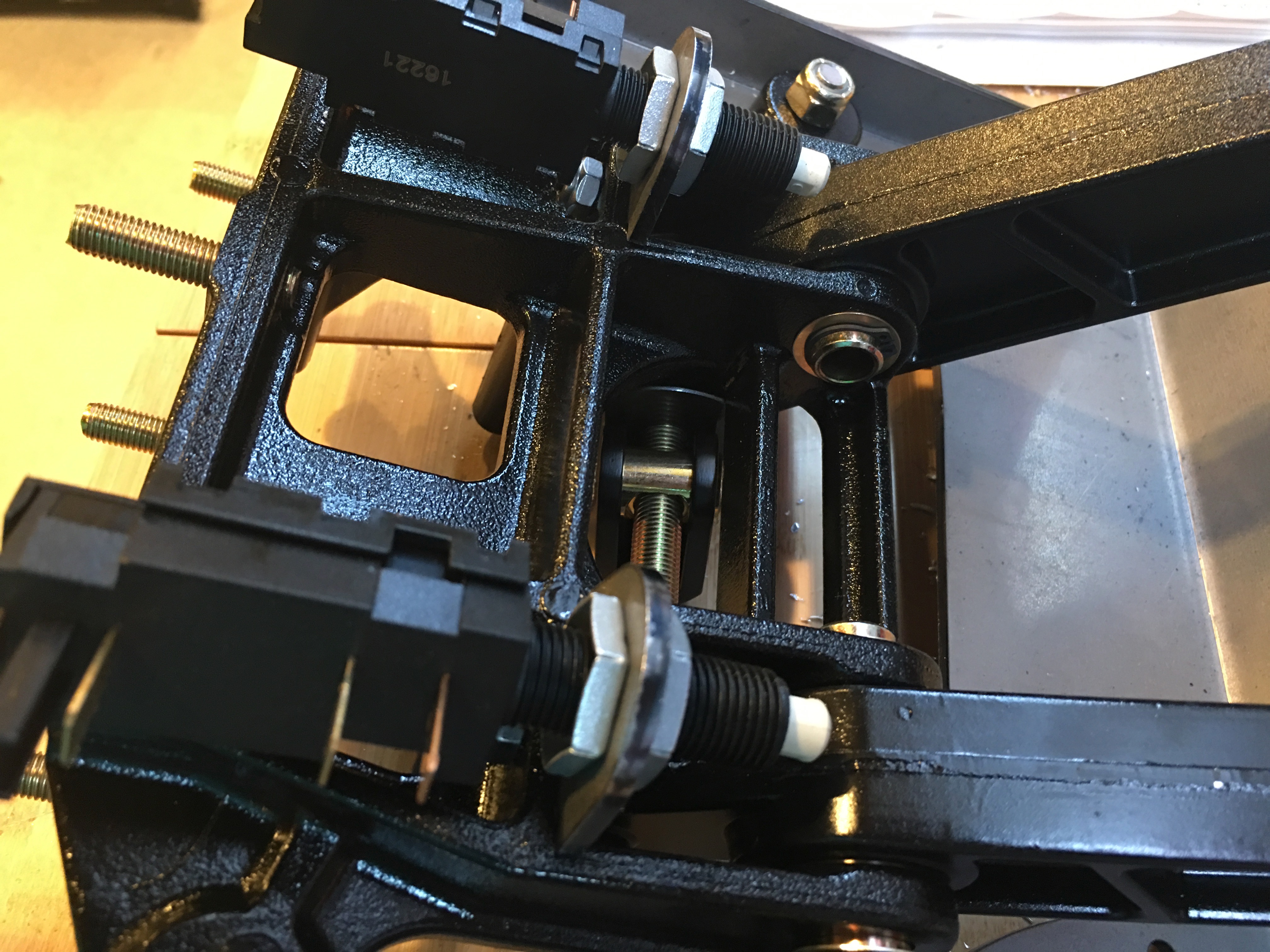
Both the clutch and brake pedals have switches installed so that systems can know when they’re depressed. The switches are mounted to tabs that need to be installed on the pedal box. To drill the holes, I clamped the tabs to the opposite side of the mounting flange since there is no room to drill from the other side. If you do this, don’t push the tab all the way down against the adjacent side flanges since they slope up toward the pedal and the hole won’t be aligned when you move the tab to the other side of the mounting flange. I just eyeballed it and it worked out great. You can see the right tab is already mounted and the left is ready to be drilled.

Once the tabs are in place, the switches can be installed. I’ll adjust the offset for these once all the systems are hooked up.

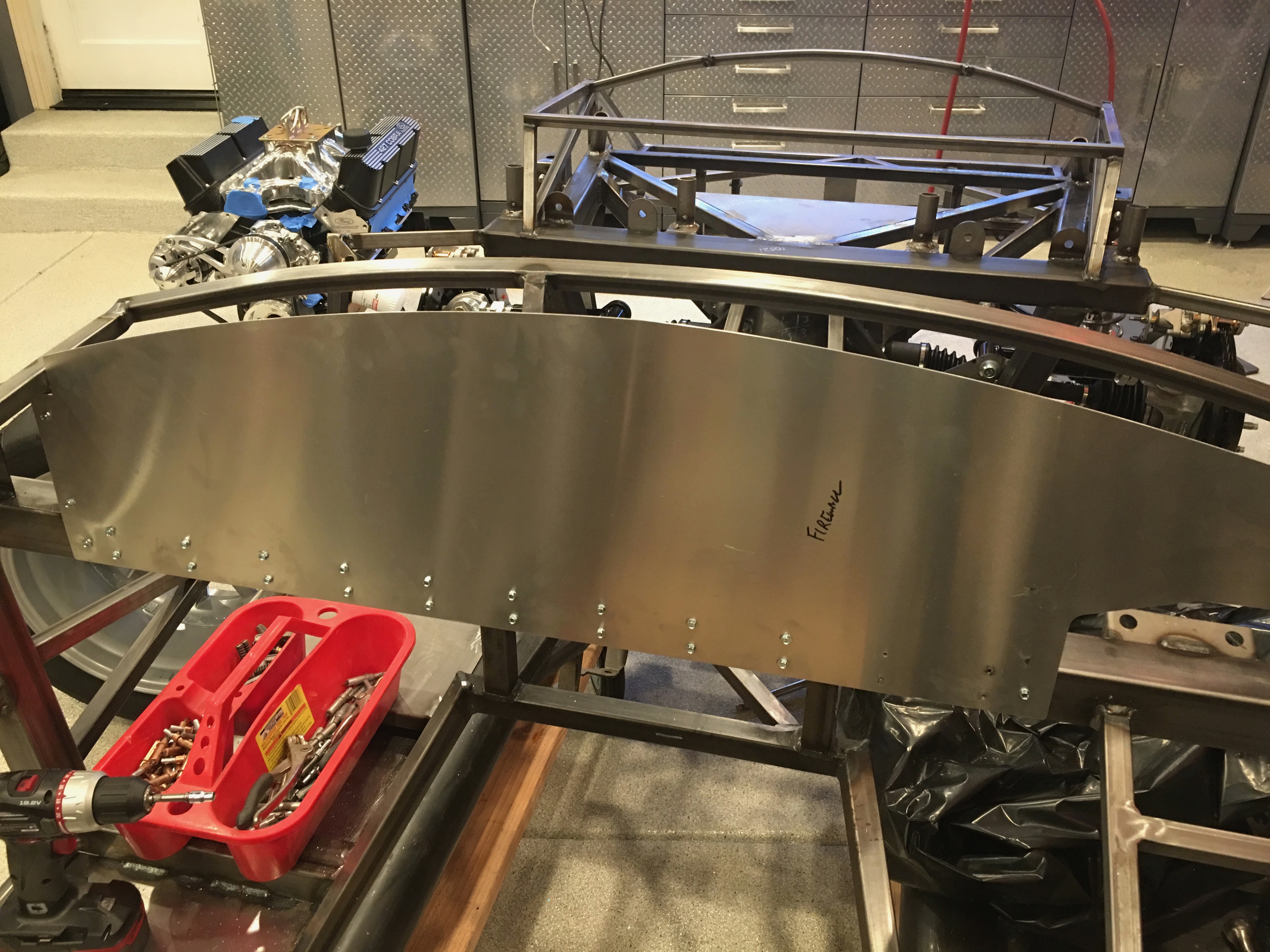
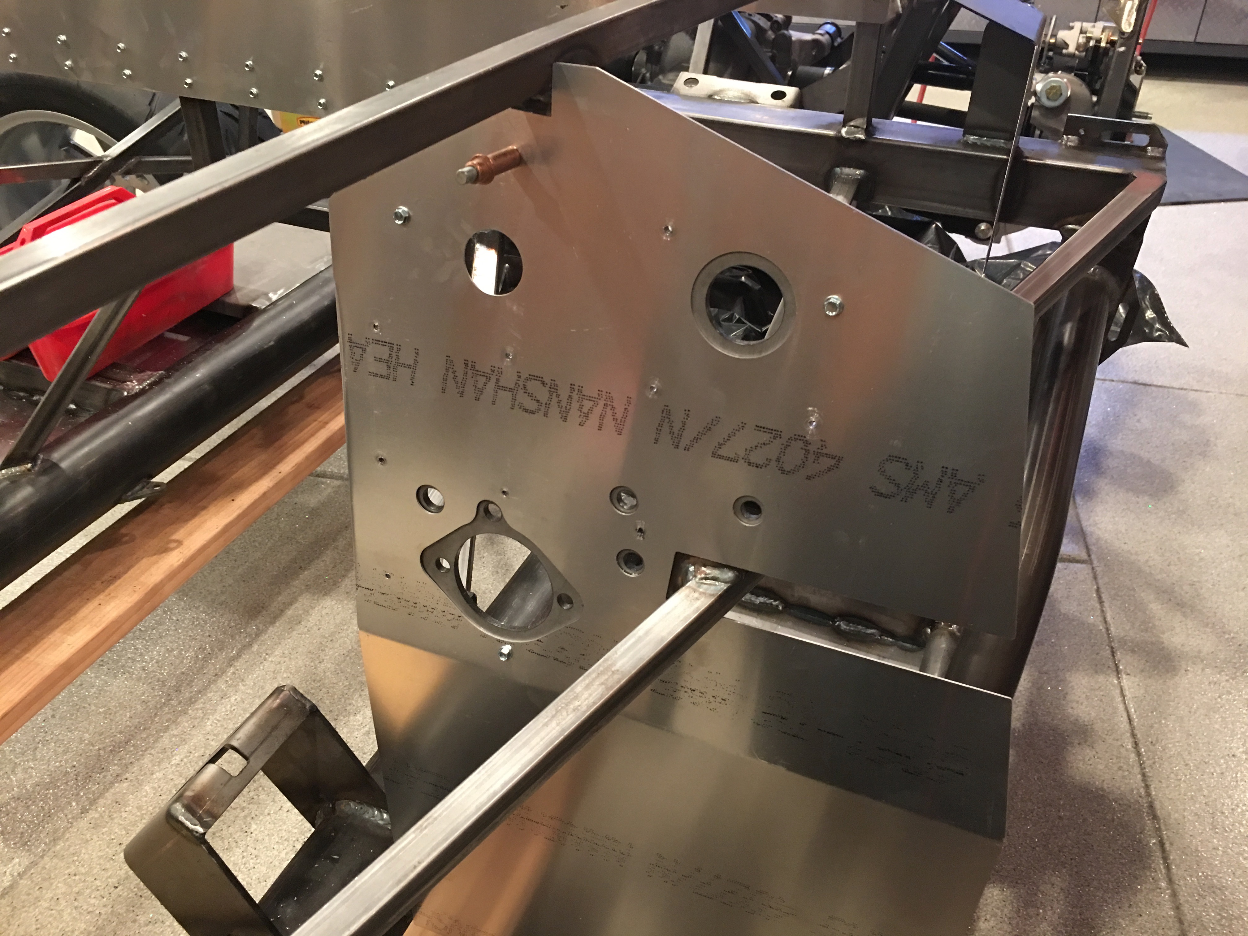
When I tried to install the pedal box in the car, two of the screws that I installed yesterday interfered. I removed them, installed the pedal box and then drilled through this flange. After removing the pedal box, I enlarged these holes to provide clearance for the screws (and eventually the rivet shop heads).

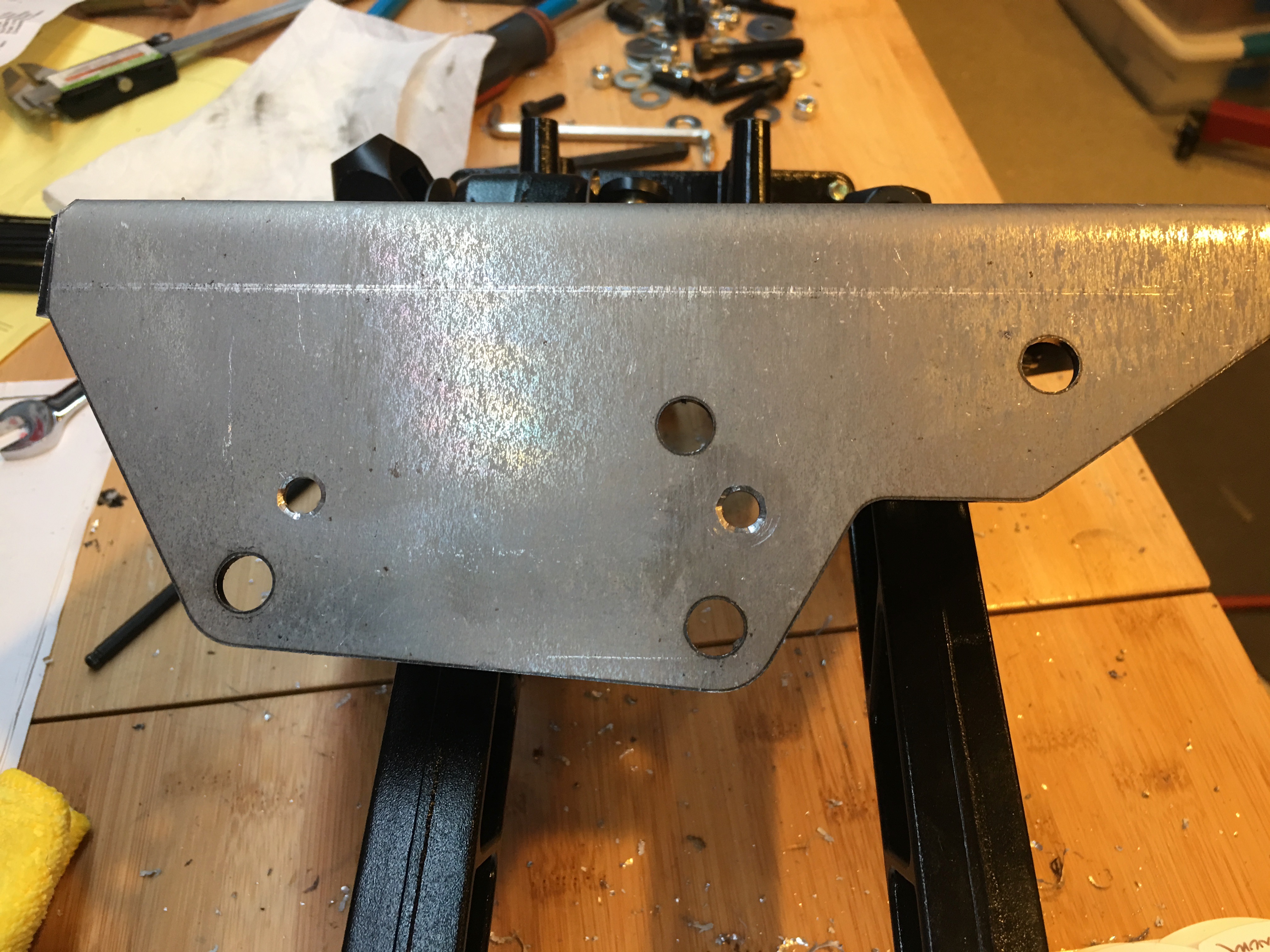
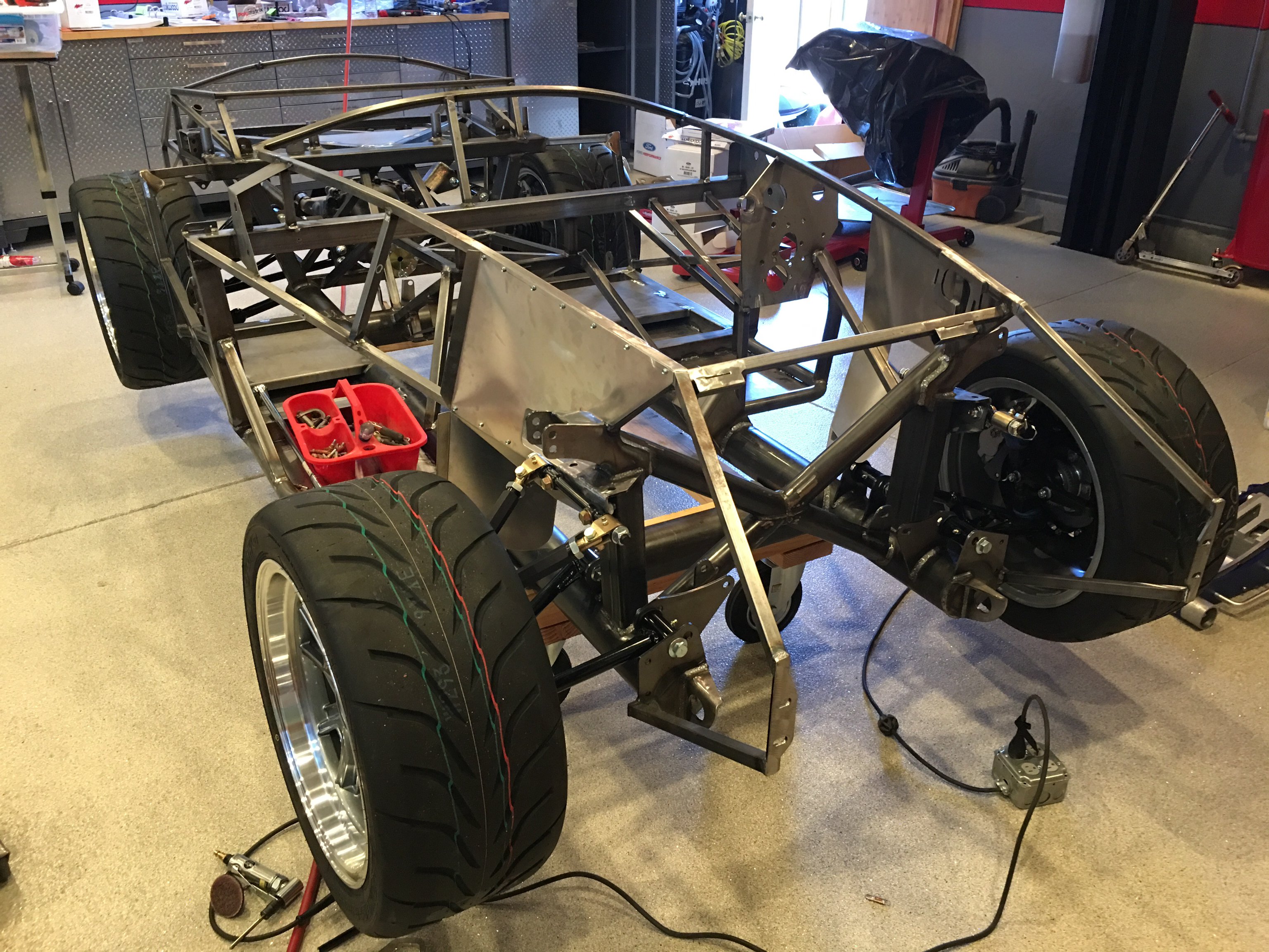
After fitting the rear mounting plate, I marked and drilled holes through the lower 3/4″ square tubing. Initially, they landed almost flush with the edge of the tubing. I couldn’t drill the holes there since that would compromise the side of the tubing. I ended up shifting the holes over about 1/16″. There is enough flex in all of the components that they can absorb some offset. You just need to make sure all of the bolts are installed loosely before tightening everything down.

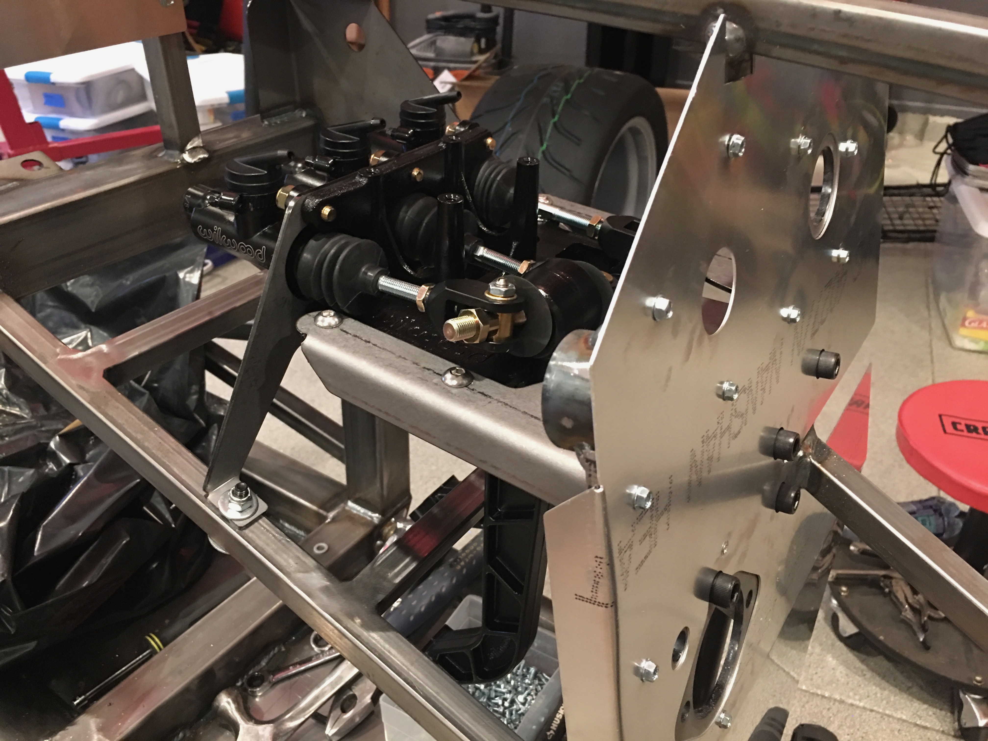
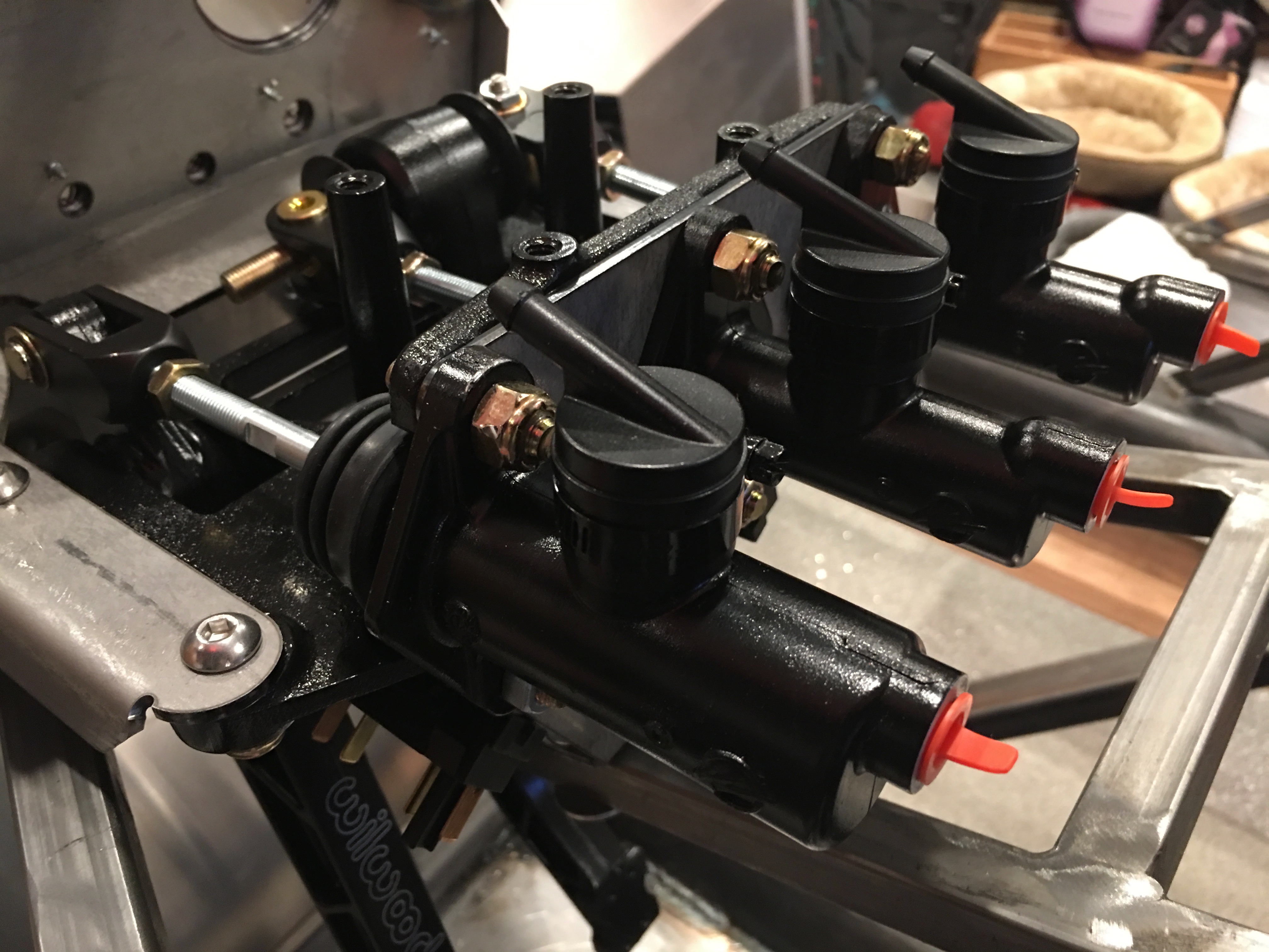
You can see that the clutch reservoir (closest in the picture) has a larger bore than the brake cylinders. After installing everything, I realized that the brake balance bar was misadjusted from the factory. I ended up removing one of the brake cylinders so that I could adjust the side-to-side clearance of the balance bar. After adjusting the balance bar, I threaded in the master cylinder shafts until the cylinders open all the way up when the pedals are released.

Parking Brake and Aluminum Panels

We’re relocating the parking brake to the top of the tunnel, so I wanted to assemble the mechanism so we could begin determining the best location. We can’t make a final determination until the transmission and seats are in place though.

Since we deleted the brakes from the kit order, we didn’t get the parking brake cables. Since we’re moving the parking brake anyway, the stock kit from FFR probably wouldn’t work without modification. Fortunately, Wilwood sells a universal kit (330-9371) that can be trimmed to exactly fit each application.

I fit and drilled the firewall to the chassis. I ran out of sheet metal screws and need to pick up some more.

I also drilled the foot box front panel to the chassis. I ended up laying out a couple of holes under the 3/4″ square tubing and needed to use a right angle drill to drill them.

Brake Touch Up Paint

I managed to put a slight scratch in one of the calipers during the initial fitment (not the one pictured). I called Wilwood, but they don’t sell touch up paint for their custom colors. They did however recommend using fingernail polish.

I stopped by a beauty supply store on the way to work today. The lady there was really helpful and let me try a bunch of different fingernail polishes until I found one that was nearly a perfect match.

Installed Front Brakes and Filled Differential

I got started this morning on the front brakes which are a little more of a pain than the rears. The bracket that holds the caliper on doesn’t fit the FFR spindles without some modification. After searching the forums, the consensus is to grind the spindle until the bracket fits. The only interference is with the upper mounting hole on the bracket, but that part of the spindle is super thick. I only needed to remove about 1/16″ of material, so strength is not compromised.

With the Big Brake kit from Levy Racing, there is very little clearance between the wheel and the caliper, so the caliper needs to be biased inboard a bit. The instructions from Gordon are to shim the caliper inboard enough that the outboard pad can just barely be inserted. I ended up using about 0.150″ thick shim to space the mounting bracket inboard which lets me insert the the outboard pad with about 0.012″ of clearance. Even though the gap is greater on the inboard side, this will even out the first time the brakes are applied. Since there are pistons on both sides, the inboard pistons will just extend a little more.

Wheel spacers are used to shim the wheels outboard about 0.090″, but that still only leaves about 0.040″ between the back of the spokes and the face of the caliper.  Since the calipers are rigidly mounted and don’t float like most OEM calipers, this is more than sufficient clearance.

The reason I wanted to get the wheels on now is that I need to measure for the struts. The manual says the chassis ride height should be 4.5″ from the ground to the bottom of the 4″ main tubes. I laid down three 2x4s and then set the chassis down on them.

I did the same thing in the front and then adjusted all four control arms to put the wheels at zero camber.

I put a couple of bolts in the upper and lower mounting brackets and measured for the ride height distance. It’s a little unclear whether the upper end of the shocks should bolt into the upper or lower hole.

I drained the differential in preparation for filling it with new fluid.

I was pleasantly surprised to see that both the fill and drain plugs both included magnets to catch any loose metallic particles floating around in the oil.

My dad brought over this contraption he made to fill transmissions and differentials. It hooks up to a compressed air source and then has a needle valve to control the air pressure in the canister. There is a pickup in the bottom of the canister that connects through a fitting to the tubing on the top. When pressurized, fluid is forced up the tube. The plastic canister can’t take much pressure, so it takes awhile to pump 2.5L of fluid up into the diff.

Installed Rear Brakes

My dad stopped by today and we worked on the rear brakes. I’m still missing the right caliper, so we got started on the left side. The bracket bolted on without any issue and the main caliper and parking brake caliper bolted up to the bracket easily. I needed to shim the bracket over slightly to center the caliper and I may still need to shim the caliper away from the axle slightly, but this is good enough to measure wheel clearance.

We wrapped up the other side (minus the caliper) and installed the rear wheels. We have about an 1/8″ gap at the closest point between the parking brake caliper and the wheel, so we’re good on clearance.

Received New Rotors and Installed Brake Hats

We received the new rotors from Wilwood today. I was super happy to see that these are also powder coated black since that will prevent rust on all of the non-braking surfaces.

I installed all of the bolts that attach the rotors to the hats with both red thread locker and safety wire. It seems unnecessary to do both (especially with red thread locker), but it wasn’t too much work and given how catastrophic a failure in this area would be, I’d rather be safe than sorry.

Received Wilwood Brakes

I received my Big Brake Kit from Levy Racing today. This is a custom color combination, so it took several weeks to get here, but we really like the look of the silver calipers with black lettering. These are larger than the Wilwood brakes that Factory Five sells by a fair amount. The rotors are 1.1″ thick which is 10% thicker, but more than 10% more massive. The mass of the rotor determines the thermal capacity and hence the amount of braking you can do before you start to get brake fade. These should be much better on the track than the set that Factory Five sells. These also use pads that are 40% larger than the factory upgrade, so we should see much better braking performance as well.

Unfortunately, one of the rear calipers was gouged (presumably during shipping).

We also received slotted rotors even though we ordered drilled and slotted rotors. I sent an email to Gordon Levy and he was quite apologetic and immediately set about making it right. Things like this happen, but I’m always happy to work with great vendors who make sure their customers are taken care of.

Ordered Brakes, Clutch and Transmission

We’ve been wrestling with which brake package to order for quite awhile. We already deleted the Mustang brakes from the kit and had decided not to go with the Wilwood package that Factory Five offers. We narrowed down the options to the Wilwood Big Brake package that Levy Racing sells or a package from Baer. For a number of reasons, we decided to go with Levy Racing. We ordered 13″ brakes front and back with a 6 piston front and 4 piston rear calipers as well as a rear spot caliper parking brake. Although Jenn was seriously considering hot pink calipers, we ultimately decided on silver calipers with black lettering. This is a custom color so it will be a couple of weeks before it ships.

I also ordered the Tremec TKO600 transmission (TCET5008), RAM HDX clutch and hydraulic clutch kit from Forte’s Parts Connection. I had been considering a hydraulic throwout bearing along with Factory Five’s hydraulic clutch kit, but after talking with Mike Forte, I decided to use his kit with an external slave cylinder. If the cylinder ever needs replacing, it won’t require pulling the transmission to get to the hydraulic throwout bearing.